Finite Element Simulation and Experimental Validation of
Manufacturing Process for Alternator Housing
Kyu-Taek Han
Department of Mechanical Engineering, Pukyong National University, Busan, 608-739, Korea *Corresponding Author: [email protected]
Copyright © 2013 Horizon Research Publishing All rights reserved.
Abstract
For the development of the manufacturing process of alternator housing, finite element simulation is applied. In recent years, automobile parts are required to be light and have high strength. The control of casting defects is important in die casting process. However, it has usually been depended on the experience of the foundry engineer. The die casting process was used to manufacture automotive alternator housings. In this paper, the die characteristics of alternator housing with the HPDC(High Pressure Die Casting) process were investigated using computer simulations. Through the simulations using the commercial software, the filling pattern and product defects could be confirmed. The computer simulation results of filling behavior were reflected to the optimal design of the alternator housing. The analysis results obtained from the filling behavior of casting process agreed with experimental results.Keywords
Alternating housing, Manufacturing Process, Finite Element Simulation, Die Casting1. Introduction
Recently the requirement of light weight and high performance automobiles has been increased. The weight of the automobile is very important from the viewpoint of fuel consumption and traveling performance. Consequently, lightweight materials such as aluminum, magnesium, and titanium comes to be more important. Optimal design techniques, material techniques, process design for parts and die design techniques need to be developed for light weight automobile parts. Die casting, melted metal poured into the die cavity in conditions high speed and high pressure, is one of the best methods. Generally the die casting is considered as an appropriate forming process to manufacture the products in which complex shapes or precision surfaces are desired. The die casting process is divided into the filling process and the solidification process. The die casting process has a series of complex temperature changes.
Incidentally, the research by experiment must have limits because it proceeded in the die cavity which is shut.[1-7] But the research which predicts and prevents the defects of products and dies is still in its early stage. Few papers[8-10] have been found in the literature, because of insufficient data of the precision manufacturing technology in die casting. Therefore in this study, the filling and solidification process were predicted using computer simulation and its results were reflected in the die design and the process design as a previous step for the development of the precision die of an automotive housing.
2. Simulation of Die Casting
2.1. Governing Equations
The flow of fluid and the heat transfer phenomenon in the governing equation are represented by the mass, momentum, and the rule of energy conservation. The governing equations used for the flow and the solidification of three dimensional incompressible flow are expressed by Eqs.(1)-(4), continuity equation(1), energy equation(2), volume of fluid(3), and Navier-Stokes equation(4). Equation(5) shows the finite differential equation for the filling.
2.1.1. Continuity Equation
0
u
v
w
x
y
z
∂
∂
∂
+
+
=
∂
∂
∂
((1)2.1.2. Energy Equation
(
)
(
)
(
)
T
T
T
c
K
K
t
x
x
y
y
T
K
z
z
ρ
∂
=
∂
∂
+
∂
∂
∂
∂
∂
∂
∂
∂
∂
+
∂
∂
(2)
F
u
F
v
F
w
F
t
x
y
z
∂
∂
∂
∂
=
+
+
∂
∂
∂
∂
(3)2.1.4. Navier-Stokes Equation
2 2 2
1
1
1
x y zu
u
u
v
u
w
u
t
x
y
z
p
u
x
v
u
v
v
v
w
v
t
x
y
z
p
v
y
w
u
w
v
w
w
w
t
x
y
z
p
w
z
g
g
g
ν
ρ
ν
ρ
ν
ρ
∂
+
∂
+
∂
+
∂
∂
∂
∂
∂
∂
= −
+
+
∂
∂
+
∂
+
∂
+
∂
∂
∂
∂
∂
∂
= −
+
+
∂
∂
+
∂
+
∂
+
∂
∂
∂
∂
∂
∂
= −
+
+
∂
∇
∇
∇
(4)2.1.5. Governing Differential Equation(GDE)
(
)
(
)
(
)
j j
j j
t
x
u
S
x
φx
φρφ
ρ φ
φ
∂
+
∂
∂
∂
∂
∂
=
+
∂
Γ
∂
(5)
where u,v,w are the direction velocity, is the kinematic viscosity, is the fluid viscosity, g is the gravity acceleration, p is the pressure, and F is the volume rate of fluid.
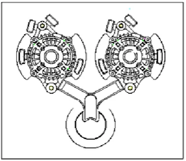
[image:2.595.57.263.70.422.2]2.2. Modeling and Preprocessor
Figure 1 shows the shape model of a motor housing and is expressed using the Unigraphics as the STL file format for recognition in commercial S/W MAGMAsoft. In the figure A is inlet and has 41181.65㎣ in volume, B is gate and has 179335.9㎣ in volume, C is ingate and has 300.7931㎣, and D is cast and has 105311.3㎣, E and F are the overflow 1 and 2 and have 171.49㎣, 3887.85㎣ in volume respectively. The motor housing shape model needs the dimensional accuracy of the average thickness 2.5∼3.5 within the maximum circularity 0.1 based on an inner diameter 100.
Figure 1. 3D Solid model of alternator housing
2.3. Input of Analysis Condition
The material of the motor housing is ADC12 and the physical properties and chemical composition for the analysis are expressed in Tables 1 and 2. The material for the die is STD61 and water is used in cooling the channel. The melting metal, after the die is closed, is poured and we add pressure after the filling of melting metal for the strength of casting and the removal of contraction hole during the solidification process. The die is opened and products are ejected after the completion of the cast solidification, and the die is shut again after spraying the surface of the die for the next cycle to begin.
Table 1. Physical properties of ADC12 alloy Properties Unit Value Initial Temp. ℃ 660
Latent Heat kJ/kg 514.2
Tliq ℃ 614
[image:2.595.272.552.80.421.2]Tsol ℃ 555
Table 2. Chemical composition of ADC12 alloy
Cu Si Mg Zn Fe Mn Ni Sn Al
3.1 11.5 0.3 0.8 0.9 0.4 0.3 0.2 R
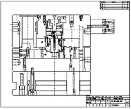
2.4. Structure of the Alternator Housing Die
Figure 2 shows the basic structure of the alternator housing die. The existing casting technique is problematic for the production of the alternator housing products in that it cannot guarantee accuracy within the maximum circularity 0.1 based on an inner diameter 100. For this reason, special purpose machines or general purpose lathes are required for machining alternator housings.
To solve the problem we designed the die after modifying the machine structure to make possible the ejecting in a fixed part.
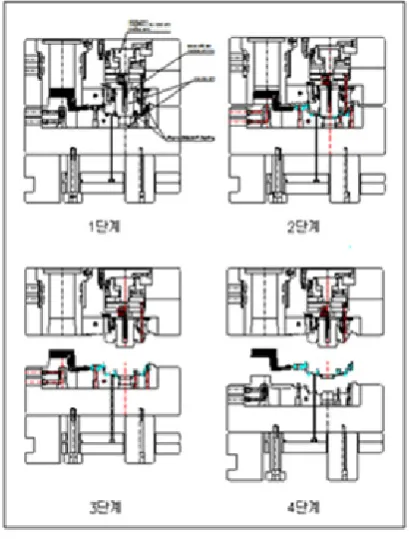
[image:2.595.322.545.541.726.2] [image:2.595.138.260.643.729.2]Figure 3 expresses the forming process of the alternator housing step by step.
Figure 3. Sequential steps of the die casting process
3. Results and Discussions
3.1. Filling Analysis
The overall filling behavior of molten metal is shown in Figure 4. The molten metal fills in a constant filling pattern due to the housing’s uniform thickness design of 2.5mm to 3.5mm as was considered in the initial form design. The molten metal was filled uniformly in a geometrically balanced alternator die. Figure 5 shows a good filling behavior where the temperature doesn't drop below the liquid state line(Tliq=614℃), because of showing filling and temperature balance in a geometrically balanced runner system with two cavities.
Figure 4. Filling behavior of alternator housing
Figure 5. Temp. distribution of alternator housing
[image:3.595.347.514.422.578.2]Figure 6. Filling behavior of alternator
Figure 7. Enlarged diagram of “A” in Figure 6
[image:3.595.67.290.595.733.2]this is in good accord with the experimental results in a later section.
3.2. Final Die Design
[image:4.595.85.274.233.396.2]Figure 8 shows the die modified with the overflow to remove the vortex of part A in Fig. 6, in accordance with the simulation results of the first design. Figure 9 shows the die made by the second design. Figure 10 shows the product formed by the second design. The filling behavior agreed with the simulation results and additional machining wasn’t needed after ejecting.
[image:4.595.87.272.423.559.2]Figure 8. Modified design of alternator housing die
[image:4.595.86.272.584.723.2]Figure 9. Photo of alternator housing die
Figure 10. Photo of alternator housing cast
4. Conclusion
In this study, we confirmed the filling pattern and product defects, and verified them using the commercial software, MAGMAsoft for the optimal design of the alternator housing. It is expected the effectiveness of a fixed quantity connected directly with it, will increase, such as the reduction of defects, quality enhancement, and a productivity increase due to this research results.
The conclusions of this research can be summarized as follows, first the overall filling pattern expressed constant flow and the filling analysis results are agreed to the filling pattern of product, and then the defects prediction and the analysis of the product and the die can be done using the computer simulation of the first die design, finally the good casting product with appropriate filling pattern can be manufactured by the application of a new die design mechanism for the maximum circularity 0.1 of product.
Acknowledgements
This study was partially supported by the grant No.2013-I-06 from the Leaders in INdustry-University Cooperation(LINC) program of the Ministry of Education at Pukyong National University.
REFERENCES
[1] J. S. Kim, T.W. Lim, Novel Techniques of High Pressure Die Casting, J. of the Korean Foundrymen's Society, Vol.18, No.3, 228-233, 1998.
[2] C. C. Tai, J. C. Lin, The Optimal Position for the Injection Gate of a Die-casting Die, J. of Materials and Technology, 86, 87-100, 1999.
[3] C. H. Lee, J. K. Choi, Die Design for High Pressure and Casting Process Analysis, the Korean Foundrymen's Society, Vol.20, 400-406, 2000.
[4] C. G .Kang, Y. I. Son, and S. W. Youn, Experimental Investigation of Semi-solid Casting and Die Design by Thermal Fluid-solidification Analysis, J. of Materials and Technology, 113, 251-256, 2001.
[5] N. Nishi, High Pressure Die Casting Process, , J. of the Japan Foundrymen's Society, Vol.71, 62-70, 1999.
[6] N. Nishi, Die Casting Technology of 21th Century, J. of the Japan Foundrymen's Society, Vol.73, 32-33, 2001.
[7] M. R. Barone, D. A. Caulk, Analysis of Liquid Metal Flow in Die Casting, Int. J. of Engineering Science, Vol. 38, 1279-1302, 2000.
[8] K. Y. Kim, Recent Trends on the Application of Computer to Solidification Processing, J. of the Korean Foundrymen's Society, Vol.11, No.4, 276-282, 1991.
and Production by Application of CAE, J. of the Japan Foundrymen's Society, Vol.67, 868-874, 1995.