Prediction of Energy Absorption of Al-based FGM Crash Box under
Quasi-static and Dynamic Loading
M. R. Zainal Abidin
1, a, S. Jamian
2,b, N. H. Muhd Nor
3,c 1Center for Graduate Studies, Universiti Tun Hussein Onn Malaysia, Parit Raja, Batu Pahat 86400 Johor, MALAYSIA
2
Department of Engineering Mechanics, Universiti Tun Hussein Onn Malaysia, Parit Raja, Batu Pahat 86400 Johor, MALAYSIA
3
Department of Department of Materials and Design Engineering, Universiti Tun Hussein Onn Malaysia, Parit Raja, Batu Pahat 86400 Johor, MALAYSIA
a
[email protected], [email protected], [email protected]
Keywords: Aluminum (Al), Crash box, Functionally grade material (FGM).
Abstract. In this study, simulations of quasi-static and dynamic loading on the Al functionally graded materials (Al FGM) crash boxes are carried out. The FGM crash box is fabricated by heat treatment method. Five different crash boxes, namely FGM0, FGM1, FGM2, FGM3 and FGM4 for the different heat treatment temperatures of 25, 500, 520, 540 and 560 °C, respectively are investigated. The simulation results of quasi-static loading test show that FGM1 has the maximum force of 97.515 kN and the highest specific energy absorption (SEA), 33.029 kJ/kg. As for dynamic loading test, FGM3 has recorded the highest maximum force, 59.379 kN and FGM2 has recorded the highest SEA, 24.17 kJ/kg. It can be concluded that the SEA of crash box is increased by introducing FGM concept.
Introduction
In the design of an automobile, crashworthiness analysis is the most important task mainly to maximize the energy absorption and reduce injury of car passengers during accidents. A crash box is a component of automotive parts for crash energy absorption which is used in the frontal crash zones, generally fixed between chassis and bumper [1, 2]. Crash box pattern should be stable and have repeatable deformation mode to reduce the effect of impact. The other factors to be considered are the weight, cost and manufacturing process of crash box.
Basically, a crash box is equipped several crash beads functionally for easily to collapse and buckling deformation. There are more than ten fundamentally different front-end crash boxes pattern have been developed [3]. The crash box pattern appearances are different depends on the types of automobile and ability energy absorption. However, the productions of complex pattern often complicate the installation process. Therefore, a simple design of crash box by introducing functionally graded materials (FGM) concepts is proposed. The main objective of crash box pattern to easily design the crash box without reduces the quality of energy absorption [4].
Generally, the effectiveness of crash box depends on the automobile velocity. Crash box protection priorities vary with car speed, at high speeds (12.5 m/s) concern is to guarantee occupant protection and reduce the aggressiveness of the crash event [5]. A crash box should transform the kinetic energy into the deformation energy in a controllable manner, retain sufficient survival space for the protected components and keep the forces and accelerations on the crash element [2].
temperature and the experimental data. Lagrange interpolation method is used to predict the variation in material properties at any point along the height of the Al FGM crash box.
Finite element modeling building
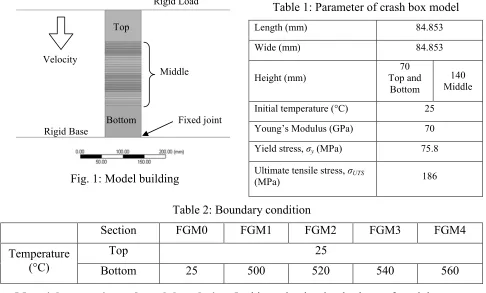
The modeling and analysis is done using finite element analysis software, ANSYS. The parameter of geometric model (Fig. 1) shows in Table 1 is modeled using shell element with thickness of 2 mm. The crash box with 280 mm height is separated to three segments, namely, Top, Middle and Bottom. Table 2 shows the boundary conditions applied for the crash box at top and bottom section during heat treatment. For more detail information of heat treatment process, the reader is referred to [6].
[image:2.595.56.542.231.524.2]Fig. 1: Model building
Table 1: Parameter of crash box model
Length (mm) 84.853
Wide (mm) 84.853
Height (mm)
70 Top and
Bottom
140 Middle
Initial temperature (°C) 25
Young’s Modulus (GPa) 70
Yield stress, σy (MPa) 75.8
Ultimate tensile stress, σUTS
(MPa) 186
Table 2: Boundary condition
Section FGM0 FGM1 FGM2 FGM3 FGM4
Temperature (°C)
Top 25
Bottom 25 500 520 540 560
Material properties and crash box design. In this study, the simple shape of crash box, square in cross-sectional area, is selected. Figure 1 show the design of crash box simulate for quasi-static and dynamic loading. Five different types of crash box are simulated, namely FGM0, FGM1, FGM2, FGM3 and FGM4. FGM0 is for homogenous crash box model (without heat treatment). Meanwhile, FGM1 until FGM4 are the crash boxes with different gradient in material properties tailored by heat treatment process. The material properties increased from top until the bottom section based on the temperature distribution result in previous study [6].
Meshing and setup. The mesh size of the crash box model are set to be 0.005 m to give the distance between two nodes 5 mm. At the bottom section, between the crash box and rigid base, all degrees of freedom are fixed.
Quasi-static loading setup. The constant loading speed of crash box is 0.1 ms-1, apply for this simulation. The end time for run the simulation is 2 s and the data is recorded at every 5 ms.
Dynamic loading setup. The load and the initial velocity of the load applied on the top of crash box model are 70 kg and 12.5 ms-1, respectively. This velocity decreases after the load hit crash box until the end time for this simulation is set to be 22.4 ms. The data is recorded at 0.02 ms.
Specific energy absorption prediction. In this study, the energy absorbing capability is estimated by the specific energy absorption (SEA) of crash box which can be calculated by:
SEA (1) Bottom
Top
Velocity
Rigid Load
Fixed joint Rigid Base
Here, Fmean is average compression force, δ is compression displacement; ρ is density, A is cross-sectional area and h is initial height of crash box.
Results and discussions
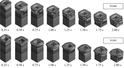
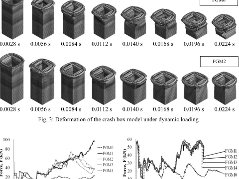
Axial collapse analysis of the FGM models demonstrative a representative shape of an automotive part was carried out in order to clarify fundamental phenomena caused of impact. Figure 2 and 3 shows the deformation pattern of the crash box for homogeneous crash box (FGM0) and the heat treatment crash box (FGM1 and FGM2) under quasi-static and dynamic loading, respectively. As shown in Fig. 2 and 3, crash deformation is started at top section where compressive strain is accumulated because the top section is the weakest compared the other section. Then, plastic buckling arises at the top section is caused by wrinkle. After that, a new plastic buckling occurs at another section of each material property just below the above wrinkle.
0.25 s 0.50 s 0.75 s 1.00 s 1.25 s 1.50 s 1.75 s 2.00 s
[image:3.595.60.541.266.531.2]0.25 s 0.50 s 0.75 s 1.00 s 1.25 s 1.50 s 1.75 s 2.00 s
Fig. 2: Deformation of the crash box model under quasi-static loading
Fig. 2 shows a pictorial sequence of progressive folding during a simulation under quasi-static loading. The simulations of quasi-static are stop after reaching crushing distance which is approximately 200 mm. The objective is to compare the energy absorption for all FGM crash boxes model.
Fig. 3 shows a pictorial sequence of progressive folding during a simulation under dynamic loading. It can be observed that the crushing force increases significantly with the test speed, although it is important to remember that quasi-static simulation are performed at a constant velocity, while dynamic simulation are impact tests at non constant velocity (the initial velocity is progressively reduced by the energy absorption). The crushing distance and energy absorption depends on the material properties of FGM crash box. Overall, the FGM crash boxes have a better crashworthiness than the homogeneous crash box under quasi-static and dynamic loading.
Figure 4 shows the simulated crash force-displacement curves of the FGM crash boxes model with different material properties strength gradient patterns under the quasi-static and dynamic loading. The load fluctuates throughout the collapse. Although the composition of materials is the same in all crash boxes, their load-displacement curve is different. As can be observed, there are almost no difference in the value of the first buckling load for all crash box model. The impact energy absorption increase and ensuring high buckling load of the crash box model. From Fig. 4(a),
FGM0
it is seen that FGM1 meets the requirements specified above which is 97.52 kN and 33.03 kJ/kg, compared to other crash boxes model. From Fig. 4(b), FGM3 have high buckling load which is 59.38 kN and FGM2 can absorbed more energy which is 24.17 kJ/kg compare the other crash box model
0.0028 s 0.0056 s 0.0084 s 0.0112 s 0.0140 s 0.0168 s 0.0196 s 0.0224 s
[image:4.595.60.540.161.521.2]0.0028 s 0.0056 s 0.0084 s 0.0112 s 0.0140 s 0.0168 s 0.0196 s 0.0224 s
Fig. 3: Deformation of the crash box model under dynamic loading
(a) quasi-static loading (b) dynamic loading
Fig. 4: Force-displacement curves
Table 3: Specific Energy Absorption model
Types FGM0 FGM1 FGM2 FGM3 FGM4
Energy absorption, SEA (kJ/kg)
Quasi-Static 12.180 33.029 28.806 28.867 27.916
Dynamic 14.203 24.121 24.170 24.132 23.896
Table 3 show the energy absorption crash boxes model under quasi-static and dynamic loading. For the quasi-static loading, the FGM1 model has the highest SEA (33.029 kJ/kg) compare to the others. Meanwhile for the dynamic loading, FGM2 seem to be the best crash box model because has the highest SEA i.e. 24.170 kJ/kg.
Conclusions
A procedure in prediction of energy absorption of Al-based FGM crash box under quasi-static and dynamic loading is developed using finite element method. From the results of analysis, the specific energy absorption of Al FGM crash box fabricated under quasi-static and dynamic loading are successfully calculated. It found that the specific energy absorption of a crash box is significantly changed if FGM concept is used.
Acknowledgement
The authors would like to acknowledge Universiti Tun Hussein Onn Malaysia (UTHM) for funding this project.
References
[1] Y. Nakazawa, K. Tamura , M. Yoshida, K. Takagi, M. Kano. in Onate, E.,Owen and D.R.J. (Eds.): Proceedings of the VIII International Conference on Computational Plasticity (COMPLAS VIII), Barcelona (2005) p. 167.
[2] A.Siva Kumar, G.Himabindu, M.Sankar Raman, K.Vijaya Kumar Reddy. Experimental Investigations with Crush Box Simulations for Different Segment Cars using LS-DYNA, International Journal of Current Engineering and Technology, Special Issue-2 (Feb 2014).
[3] P.Schwanitz, D. Göhlich, W.J. S. Werner, J. Zerbe. A New Methodology for Robust Optimization of Vehicle Structures, in online prosiding of 4th International Conference on Impact Loading of Lightweight Structures 2014, Jan 12 – 16, Cape Town. Infomation on http://icills2014.org/wp-content/uploads/2014/01/Pit-Schwanitz.pdf.
[4] P. Hosseini Tehrani1, M.Talebi. Stress and Temperature Distribution Study in a Functionally Graded Brake Disk, International Journal of Automotive Engineering,Vol. 2, Number 3, July 2012.
[5] European Aluminium Association. Design – Case study: Crash Management Systems (CMS), THE ALUMINIUM AUTOMOTIVE MANUAL (2011).