International Journal of Emerging Technology and Advanced Engineering
Website: www.ijetae.com (ISSN 2250-2459, Volume 2, Issue 9, September 2012)272
A DESIGN AND MODELING TECHNIQUES FOR
MAXIMUM POWER OPTIMIZATION ON WIND
ELECTRICAL POWER SYSTEM WITH VARIABLE SPEED
GENERATION USING NEURO FUZZY.
I. ARUL
1, DR.M.KARTHIKEYAN
2, DR.N.KRISHNAN
4, S. MUTHUKUMAR
31Research Scholar, Centre for Information Technology and Engineering, M.S University, Tirunelveli, India
2Prof. & Head, Department of ECE, Tamilnadu College of Engineering, Coimbatore ,India.
3 Prof. & Head , Centre for Information Technology and Engineering, M.S University, Tirunelveli, India
4Registrar (In-charge), National Institute of Technology, Puducherry, India.
Abstract - One of the greatest challenges associated with wind power is the unpredictable character of the wind. Wind energy is one of the lowest-priced renewable energy technologies available today, costing between 4 and 6 cents per kilowatt-hour, depending upon the wind resource and project financing of the particular project. In our research, a design and modeling technique has been proposed to optimize the maximum power extraction. An intelligent neuro fuzzy controller can keep track of variable speed generator with respect to the velocity of wind. The main objective of this paper is to fully control the wind turbine system with induction generator to maximize the power generation. The output power of a wind turbine is function of wind velocity cubed. The system has been optimized for operating around 15 m/s, and though the wind power continues to increase above this point. In addition, a neuro-fuzzy controller is also proposed for obtaining maximum power optimization. A variable speed wind turbine utilizes the available wind resource more efficiently than a fixed speed wind turbine, especially during light wind conditions.
Keywords - DFIG, Neuro-Fuzzy Controller, Power Optimization, Pitch angle, Variable speed generation, Wind Energy s
I. INTRODUCTION
Wind energy has steadily established itself as one of the most reliable and affordable renewable energy resources. The aim is to ensure that by 2030, wind energy will be the most cost-efficient energy source on the market. However, with the growing demand for green electricity worldwide, rising turbine costs and increased competition to supply green electricity to the grid, wind farm operators must improve their existing power output. In India, the total installed capacity of wind power generation is 8754 MW in the year 2008.
By the end of 2012, the total installed capacity is going to be reached to 12000 MW according to ministry of new and renewable energy, India and total installed capacity of wind energy is estimated to be more than 160 GW [WWEA] all around the world [1].
The scopes includes the simulation and modeling of DC motor, implementation of fuzzy logic controller to actual DC motor and comparison between MATLAB simulation and experimental result. This research was about to introduce the new ability of estimating variable speed and control the DC motor. By using the controller, the speed can be tuned until it get similar to the desired output that user need. In this paper, neural networks are used in a novel way to solve the problem of tuning a fuzzy logic controller. The neuro fuzzy controller uses the neural network learning techniques to tune the membership functions while keeping the semantics of the fuzzy logic controller intact. Both the architecture and the learning algorithm are presented for a general neuro fuzzy controller. From this general neuro fuzzy controller, a proportional neuro fuzzy controller is derived.
Wind energy has been the subject of much recent research and development. In-order to overcome the problems associated with fixed speed wind turbine system and to maximize the wind energy capture, many new wind farms will employ variable speed wind turbine. DFIG (Double Fed Induction Generator) is one of the components of Variable speed wind turbine system.
International Journal of Emerging Technology and Advanced Engineering
Website: www.ijetae.com (ISSN 2250-2459, Volume 2, Issue 9, September 2012)273
A DFIG is a special type of induction generator with a wound rotor. By proper control of the rotor converter, a DFIG’s can achieve reactive power control and a wider speed range than for a cage-type induction generator. Variable speed operation allows the DFIG to capture a greater amount of power in the wind for a given wind speed. There are three main advantages of a DFIG [10]. First, the variable speed operation. Second, a small amount of rotor reactive power becomes a large amount of stator reactive power. Third, the rotor converter only needs to be rated for a fraction of the total generator rating.
A variable speed induction motor drive system is developed to simulate characteristics of real wind turbines. The wind turbine simulator controller accepts the motor torque and speed as feedback signals, calculates current and frequency demands of the three-phase drive inverter based on the dynamic wind turbine model [2].
II. BASIC CONCEPTS
A. Wind Turbine
The simplest model of a wind turbine is the so-called actuator disc model where the turbine is replaced by a circular disc through which the airstream flows with a velocity Ut and across which there is a pressure drop from P1 to P2 as shown in the sketch. At the outset, it is important to stress that the actuator disc theory is useful (as will be shown) in discussing overall efficiencies of turbines but it does not help at all with how to design the turbine blades to achieve a desired performance.
The power developed by the wind turbine is Power =(P1-P2)At Ud (1)
where At is the turbine disc area. Volume flow continuity gives
AuUu = Ad Ud = AtUt (2)
B. Variable Speed Operation
The aerodynamic theory that justifies the benefit of the variable speed operation is well described in a number of independent sources. In short, the aerodynamics of the blades is such that for a particular wind speed, there is a particular rotational speed that captures the largest amount of power passing through the swept area.
Pw = ½ π ρr2V3w (3)
Here ρ is the air density, r is the area radius (blade-length) and Vw is the wind speed (all in SI units). Not all of this power can be captured by the wind turbine.
The theoretical limit set by Betz’s law states that the maximum amount of wind power Pw that can be captured by the turbine is about 59 percent. This amount of available power captured by the turbine is called the coefficient of power (Cp). The total power capture by the turbine,
Pt = Pw × Cp (4)
(5)
Although the theoretical limit is 0.59, in practice most turbines have a maximum Cp around 0.45. Cp is itself a complicated function of aerodynamic factors, including the tip speed ratio, and the pitch angle of the blades (β). To emphasize this, the coefficient of power can be written as Cp. The tip speed ratio is the ratio of the linear velocity of the turbine blade tip to the wind speed.
C. Mean power with wind speed.
Due to the non-linear variation of power with steady wind speed, the mean power obtained over time in a variable wind with a mean velocity Um is not the same as
the power obtained in a steady wind of the same speed. Thus, the mean power Pm(Um) at a mean speed Um is
given by
(6)
D. Fuzzy Logic Controller:
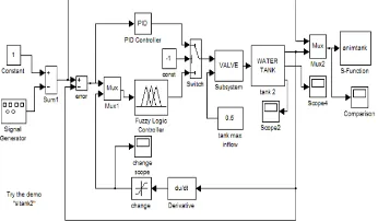
[image:2.612.359.532.555.656.2]Fuzzy Logic Controller (FLC) is based on fuzzy logic controller and constitutes a way of converting linguistic control strategy into an automatic by generating a rule base which controls the behavior of the system. Rule based fuzzy logic controllers are useful when the system dynamics are not well known or when they contain significant non-linearities, such as the un-stationary wind contains large turbulence.
International Journal of Emerging Technology and Advanced Engineering
Website: www.ijetae.com (ISSN 2250-2459, Volume 2, Issue 9, September 2012)274
The mean wind speed wm, which used as the third input
variable, is useful to compensate the non-linear sensitivity of pitch angle to the wind speed. The pitch angle of the fuzzy logic controller is less active than conventional pitch angle control with power or wind speed controlling variable, which causes less dynamic torque
E. Power Control for Wind Turbines
[image:3.612.71.266.311.415.2]When a generator reaches rated power, the turbines must limit the mechanical power delivered to the generator. This is valid because the generator reaches the rated power at for instance 15 m/s while the maximum speed is typically 25 m/s for a wind turbine. The pitch angle is controlled to keep the generator power at rated power by reducing the angle of the blades.
Figure 2. Pitch angle control structure
III. MODELING AND SIMULATION
A. Doubly fed induction motor:
[image:3.612.343.542.398.515.2]Wind turbines use a doubly-fed induction generator (DFIG) consisting of a wound rotor induction generator and an AC/DC/AC I GBT-based PWM converter. The stator winding is connected directly to the 60 Hz grid while the rotor is fed at variable frequency through the AC/DC/AC converter. The DFIG technology allows extracting maximum energy from the wind for low wind speeds by optimizing the turbine speed, while minimizing mechanical stresses on the turbine during gusts of wind. The optimum turbine speed producing maximum mechanical energy for a given wind speed is proportional to the wind speed.
Figure 3. Structure of doubly fed induction generator
The doubly fed induction machine (DFIM) is for variable-speed applications like electric vehicles and electrical energy production and variable-speed domain and performance depends on the application.
The DFIM is fed and controlled stator or rotor with many possible combinations. The input-commands are obtained by four degrees of control freedom relatively to the squirrel cage induction machine and its control appears simpler. The flux orientation strategy transforms the non linear and coupled DFIM mathematical model to a linear model conducting, attractive solution, and generating or motoring operations.
The principle of the DFIG is that rotor windings are connected to the grid via slip rings and back-to-back voltage source converter that controls both the rotor and the grid currents. Thus rotor frequency can freely differ from the grid frequency (50 or 60 Hz). By controlling the rotor currents by the converter it is possible to adjust the active and reactive power fed to the grid from the stator independently of the generators turning speed. The control principle used is either the two-axis current vector control or Direct Torque Control (DTC).
Figure 4. Operation of DFIG
DTC has turned out to have better stability than current vector control especially when high reactive currents are required from the generator. The AC/DC/AC converter is divided into two components: the rotor-side converter (Crotor) and the grid-side converter (Cgrid). Crotor
and Cgrid are Voltage-Sourced Converters that use
forced-commutated power electronic devices (IGBTs) to synthesize an AC voltage from a DC voltage source. A capacitor connected on the DC side acts as the DC voltage source. A coupling inductor L is used to connect Cgrid to the
grid. The three-phase rotor winding is connected to Crotor by
[image:3.612.76.262.607.695.2]International Journal of Emerging Technology and Advanced Engineering
Website: www.ijetae.com (ISSN 2250-2459, Volume 2, Issue 9, September 2012)275
The control system generates the pitch angle command and the voltage command signals Vr and Vgc for Crotor and
Cgrid respectively in order to control the power of the wind
turbine, the DC bus voltage and the reactive power or the voltage at the grid terminals.
B. Neuro Fuzzy Controller Design
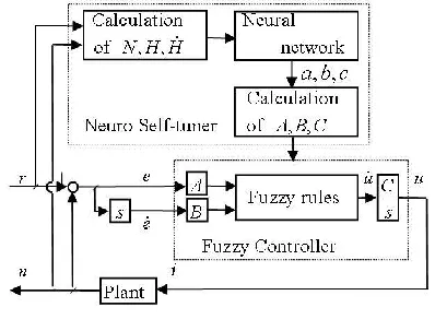
[image:4.612.354.538.132.222.2]In recent years, fuzzy logic control has played an increasing and significant role in the development and design of real-time control applications. However, membership function type, number of rules and correct selection of parameters of fuzzy controller are very important to obtain desired performance in the system. Determination of membership function type and rule number of fuzzy controller and selection of parameters is made by means of trial and error method and by using the specialization knowledge. The main purpose of using the Neuro-Fuzzy approach is to automatically realize the fuzzy system by using the neural network methods. A combination of neural networks and fuzzy logic offers the possibility of solving tuning problems and design difficulties of fuzzy logic. In this paper, a neuro-fuzzy controller architecture is proposed, which is an improvement over the existing neuro fuzzy controllers.
Figure 5. Structure of Neuro-Fuzzy Controller
[image:4.612.69.268.414.560.2]Neuro fuzzy controller can basically learn any static input-output characteristics if the training data is available. This means that the learning algorithm can produce a neuro fuzzy controller which can copy the control surface of an existing controller if the input-output data from the controller is known.
Fig 6. Three-phase wound-rotor induction machine operating as a doubly-fed induction generator.
IV. SIMULATION STUDY
The intelligent neuro-fuzzy algorithm for maximizing the performance of the wind energy conversion system has been simulated using SimPowersystems in MATLAB 7.10 software. The test environment is shown as Fig. 7, where a wind turbine simulator system is used as the prime mover to drive a asynchronous generator in replacement of a real wind turbine. The max-power algorithm is implemented using neuro-fuzzy logic based controller which effectively controls the pitch angle of the system.
Various simulation studies have been conducted based on the developed algorithm. Fig. 8-10 shows the test results without online training, under a constant wind speed set at 10 m/s.
[image:4.612.326.564.438.568.2]International Journal of Emerging Technology and Advanced Engineering
Website: www.ijetae.com (ISSN 2250-2459, Volume 2, Issue 9, September 2012)276
0 0.1 0.2 0.3 0.4 0.5 0.6 0.7 0.8 0.9 10.5 0.6 0.7 0.8 0.9 1 1.1 Time(s) R ot or S pe ed ( pu )
Fig.8 Rotor Speed of the DFIG
0.75 0.8 0.85 0.9 0.95 1
-1 -0.8 -0.6 -0.4 -0.2 0 0.2 0.4 0.6 0.8 1 Time(s) V ol ta ge ( pu )
Fig.9 Voltage generated in pu
0.75 0.8 0.85 0.9 0.95 1
-0.4 -0.3 -0.2 -0.1 0 0.1 0.2 0.3 0.4 Time(s) C ur re nt ( pu )
Fig.10 Measured Current in pu
V. CONCLUSION
The work presented in this paper is devoted to the analysis, modeling and simulation of a variable speed wind turbine using a doubly fed induction. To obtain high quality power from the wind power generation system (VSWPGS), the effective value of output voltage must be at 400 volt and frequency in 50 Hz operational limit values.
For this purpose, power limitation or speed control of the variable speed wind turbine is performed by means of controlling of turbine blade pitch angle. As a result of controlling of the wind turbine blade pitch angle, it is determined from the simulation results that the output electrical magnitudes of VSWPGS (voltage, current, frequency and power) reach to desirable values within 1.5 seconds. Simulation results demonstrate that the proposed wind turbine generator is feasible and has many advantages.
REFERENCES
[1 ] B.Chitti Babu , K.B.Mohanty “Doubly-Fed Induction Generator for Variable Speed Wind Energy Conversion Systems- Modeling & Simulation “International Journal of Computer and Electrical Engineering,February, 2010.
[2 ] Quincy Wang, and Liuchen Chang, “An Intelligent Maximum Power Extraction Algorithm for Inverter-Based Variable Speed Wind Turbine Systems” IEEE Transactions On Power Electronics, September 2004.
[3 ] Whei-Min Lin, Chih-Ming Hong, and Chiung-Hsing Chen “Neural-Network-Based MPPT Control of a Stand-Alone Hybrid Power Generation System” IEEE Transactions On Power Electronics, December 2011.
[4 ] Pengwei Sun, Chuang Liu, Jih-Sheng Lai, Fellow, IEEE, and Chien-Liang Chen, “Grid-Tie Control of Cascade Dual-Buck Inverter With Wide-Range Power Flow Capability for Renewable Energy Applications” IEEE Transactions On Power Electronics, April 2012. [5 ] Shuhui Li, Senior Member, IEEE, Timothy A. Haskew, Senior
Member, IEEE, Richard P. Swatloski, and William Gathings “Optimal and Direct-Current Vector Control of Direct-Driven PMSG Wind Turbines “IEEE Transactions On Power Electronics, May 2012.
[6 ] Yu-Lin Juan, Member, IEEE “An Integrated-Controlled AC/DC Interface for Microscale Wind Power Generation Systems” IEEE Transactions On Power Electronics, May 2011.
[7 ] Xibo Yuan, Fei (Fred) Wang, Dushan Boroyevich, Fellow, Yongdong Li and Rolando Burgos, Member, IEEE “DC-link Voltage Control of a Full Power Converter for Wind Generator Operating in Weak-Grid Systems” IEEE Transactions On Power Electronics, September 2009.
[8 ] Wei Qiao, Wei Zhou, José M. Aller, and Ronald G. Harley, Fellow, IEEE “Wind Speed Estimation Based Sensorless Output Maximization Control for a Wind Turbine Driving a DFIG” IEEE transactions on power electronics, may 2008.
[9 ] Yuanye Xia, Khaled H. Ahmed, and Barry W. Williams “A New Maximum Power Point Tracking Technique for Permanent Magnet Synchronous Generator Based Wind Energy Conversion System” IEEE transactions on power Electronics, vol. 26, no. 12, december 2011.
[10 ]Kostyantyn Protsenko and Dewei Xu “Modeling and Control of Brushless Doubly-Fed Induction Generators in Wind Energy Applications” Department of Electrical and Computer Engineering Ryerson University, canada.
International Journal of Emerging Technology and Advanced Engineering
Website: www.ijetae.com (ISSN 2250-2459, Volume 2, Issue 9, September 2012)277
[12 ]Hans Øverseth Røstøen ,Tore M. Undeland,Terje Gjengedal “Doubly Fed Induction Generator In A Wind Turbine” Norwegian University of Science and Technology.
[13 ]D.Aouzellag , K.Ghedamsi,, E.M.Berkouk “ Power Control of a Variable Speed Wind Turbine Driving an DFIG” Electrical engineering Department, A.Mira University, Bejaïa, Algeria. [14 ]Jaime R. Arribas, Carlos Veganzones, Francisco Blázquez, Member,