New technique
for
the
interpretation of ISO
14649
and
6983 based
on
open
CNC
technology
Yusri Yusofx and Kamran
Latif
Faculty of Mechanical and Man4facturing Engineering, (Jniversiti Tun Hus.sein Onn Malaysia PTHM), Parit Raja, Malaysia
(Received 3 July 2014; accepted l8 January 2015)
Computer numerical control (CNC) controller is the termination organiser, which is located at the end of the manufacturing process chain. The CNC controller is composed of two modules: software and hardware. The software module of the
lontroller is known as interpreter that translates Intemational Standards Organization (lSO) data interface model instructions to the hardware parts of the controller in the required structure of the machine. The aim of next-generation CNC is to be
portable, interoplrable, flexible, open, intelligent and adoptable. In the progression towards the development of next-generation CNC systerns, the problems
of
current ISO data interlace model limitation and CNC machine vendor dependency were ficed. In order to overcome these issues, the ISO standard 0SO 14649) and open architecture control(OAC) techrology were introduced. ln this paper, a new technique for the interpretation ofboth ISO data interface models has been pr"."nied. The developed module is specially designed for the OAC-based CNC systems that translate the ISO 14649-2I and ISO 6983 information to the CNC machine in required structure. The module also provides a shop floor
editing facility and is also able to generate the physical file output in user-defined structure
of.txt
and .xml formats.Keywords: CNC; STEP-NC; interpreter; CAD/CAM; open architecture control; LabVIEW
International Journ al o/ Computer Integrated Manufacturing, 201 5
http://dx.doi.org/l 0. I 080/095 I I 92X.20 I 5. I 030698
l.
Introduction
In
the
1950s,a
revolutionary change occurredin
the manufacturingworld
with
the introductionof
numerical control (NC) machine tools. NC is the term used to deflnethe
controlof
machine movementswith
other various functionsthat
transfersthe
instructionsin
a
seriesof
numbers via an electronic control system (Liang, Hecker,
and
Landers2004).
The next
significant development towards machine automation occurredin
the 1960s withthe
introductionof
direct
NC. This
systemallows
the programmers to send program files directly to the machine unit via central control system (Ramesh, Jyothirmai, and Lavanya 2013). Later, in the 1970s, a major revolutionary change occurredin
machinetool
automationwith
the developmentof
the coutputer numerical control (CNC), where a computer replaced mostof
the electronic hard-ware and punch cards of the NC machine (Liang, Hecker, and Landers 2004).The
CNC
machineworks
on
the technologythat
uses minicomputersto
generate, parseand execute the sequential control. These CNC machines
are
composedof
minicomputersand
computer-aided design(CAD)
drawing softwareto
support the develop-mentof
on-machine programsto
enable machiningof
different parts (Talavage 1987). These
CNC
machines are classified into different categories like machining pro-cess, numberof
axes, spindle alrangement, numberof
spindles
and
kinematics configuration (Stenerson and Cunan 2005; Vichareet al.
2009).The
applicationof
this technique
is
often usedin
tuming,drilling,
milling,Taylor & Francis
electronic component insertion, tube welding and cutting robots (Groover 2007).
In
the
progression towardsmore
modern systems,flexible
manufacturing became dominantin
the
1970sand the 1980s
to
enable low-batch productionof
a wide rangeof
parts.In
order to realise flexible manufacturing, CNC machines became a critical manufacturing resource due to their capability for being reprogrammed to produce different parts(Xu
and Newman 2006). CNC technology has provedto
be economicalin
mass, batch and many other single-item production cases. Someof
the
most important factors which contribute towards the economic feasibility of CNC technology are high productivity rates'uniformity
of
the product, reduced component rejection,reduced tooling costs, less operator involvement and easy
machining of complex shapes (Yusof, Kassim, and Zamti Tan
20ll).
Today
in
industries,
many
CNC
machines areemployed
with
different controllers and multiple abilitiesto
fulfiI
customer demands. TheseCNC
machines arecomposed
of
many
parts;the
controlleris
oneof
the parts that hastwo
modules inside: hardware module andsoftware module. The function
of
the software module isto translate the input International Standards Organization (ISO) data interface model code to the intemal structure
of
the machine. CNC controller reads the ISO data interface model instructions, interprets them and performs numeri-cally direct interpolationof
the cuttingtool in
the work-piece(Ertell
1969). The machine controllers interpret the o{oo
:
a.l
-
oc)
J
! 6
() E
B
*Corresponding author. Email: yusri(@uthm.edu.my
N !
oo
:c
(\
r o
J
v
o
d
part program to control the tool rnotion with multiple axes.
The interpreter of the CNC system is the software module
ofthe
controller unit that translates the part programcon-sisting of code commands and related addresses into inter-nal commands
for
moving tools and executing auxiliary functions in a CNC system.The
CNC
machines are programmedin
ISO
6983, formally known asG&M
codes language(ISO
6983-1 1982). The currentCNC
language, the so-calledG&M
codes, has been used since the 1950s. The programs for
the CNC
machinesare
generatedby
computer-aided manufacturing(CAM)
systems that useCAD
informa-tion. TheG&M
codes language is defined by justnumer-ical
codes such asG,
I
M,
F,
S, etc.,
indicating themovement
of
a
machine andan
axisto
the controller. Meanwhile, this language deliversonly
limitedinforma-tion
to the CNC, which makes the CNC nothing but anexecuting mechanism which is completely unaware from the motions being executed. However, with the growth in the manufacturing world, there are a number of problems found
in
this
data interface such asdelivering
limited informationto
CNC,
transferring one-way information from CAD/CAM to CNC, unable to implement the seam-less integration of theCAD-CAM-CNC,
etc. (S.H.
Suhand
Cheon2002).
Also, the
developmentof
various CAD/computer-aided processplanning
(CAPPyCAM/ CNC systems in the CAx process chain created a require-ment for data exchange standardsto
enable smooth data integration between machines and systems from different vendors. Behind these drawbacksin
realify, G-code pro-grams arestill
very valuablein
cornmercialmanufactur-ing
systems becausethey
incorporateboth an implicit
microprocess plan and many years ofoperator experience
(Shin,
Suh,and
Stroud2007).
These codesare
wellaccepted worldwide and are
still in
use;for
this reason,a
functionality
of
G-code
interpretation
has
beenincluded
in
this system.In
order
to
overcome interoperability issues,
aStandard
for
the Exchangeof
Product Data (STEP) was introducedin
the
1990s(ISO
1991;I.
ISO
1994). The objectiveof
STEPis to
providea
rleansof
describing product data throughout thelife
cycle that is independent from any particular computer system. The initial releaseof
STEP was published
in
1994 by ISO, in which parts 1, I I ,21,31,
42, 43, 44,46
and 101, and application protocols(AP)
201 andAP
203 were introduced(T.
ISO
1994).Later
in
2002,AP
202,
AP
209,
AP
214,
etc., were publishedby
ISO; these APs had enablednore
skills in the STEP for different industries. With the developmentof
various STEP parts andAPs,
some problems emerged with these large data structures; these problems were rec-tified with the introduction of the STEP modulararchitec-ture
(Houshmandand Yahlai 2012;
Feeney
2002). Cunently, AP 242 is being developed, which is based on geometric dimensionsand
tolerancesin
combinationwith
STEPAP
203
and
214
(Safaieh, Nassehi, andNewman 2013).
ISO
10303 significantly improved theinteroperability between
CAD
systems. This standard hasalso highlighted the need for the development of a similar standard
for
exchangeof
information
between CNC machinesas
well
as
CAM
systems. Consequently, in 1999an
internationalproject was
startedto
specifu anew
standardentitled
ISO
14649,formally known
asSTEP-NC,
to
bring
the benefitsof
STEPto CAM
andCNC (S.-H. Suh, Cho, and Hong 2002). The
ISO
14649standard is an extension
of ISO
10303, which allows theconnections between STEP-based
CAx
and CNC. This standardis
still
in
the
developing phaseunder
twodifferent
subcommittees(SC)
of
Technical Committee(TC)
184 under ISO:SCI
and SC4. ISO 14649 is underSC 1 of
TC
184 that focused on the machine control. This model is for CNC known as application reference model, whereasISO
10303-238is
under SC4 of TC
184 that focused on the industrial data. This model isfor
applica-tion
interpretedmodel
for
CNCs
(Feeneyet al.
2003;Hardwick
et al.
2013).Actually
ISO
10303-238is
anupgradation
of
ISO
14649; the difference between them is highlightedin
Hardwick et al. (2013) and Krzic, Stoic, and Kopac (2009).The
STEP-NC code containshigh
levelof
informa-tion.
It
hastwo
sections:'HEADER'
and'DATA'.
The'HEADER'section contains the information of
file
name,author, date, etc., whereas the 'DATA' section contains all the information about manufacturing tasks and geometries. In this section, the project entity is the starting point ofthe program execution,
which
indicates the workplanto
beexecuted and the workpiece upon which operations have
to be performed. The workplan contains a series
of
man-ufacturing tasks including informationof
workpiece.It
iscomposed
of
three different typesof
executables: work-ingsteps,NC
functions and program structures. Among those workingsteps, executableis
the
most
important becauseit
defines manufacturing features such as 2.5D and3D
regions. Each workingstep also defines sub-fea-tures such as planar_face, pocket, slot, round-hole, etc.,with
cutting condition information. The workingstep alsocontains features and machining operations data; the fea-tures
of
workingstep contain geometrical data and themachining
operationscontain generally omitted
toolpaths,
tool
and
machining functions
data
includingmachining information and
NC
commands.In
particular,this
includes data regarding tools, machining strategies,definitions of workpiece, etc. For further details regarding
the ISO
STEP-NCfile
structure,refer
Calabrese andCelentano
(2007), Krzic, Stoic, and Kopac
(2009), Y. Zhang et al. (2010) andXu
and He (2004).The introduction of ISO 14649 recovers the
informa-tion
loss from CAD/CAPP/CAM to CNC and makes theCNC
more open, interoperable and intelligent(Xu
andInternation al Journal of' Computer Integrated Manu/itcturing
a.l
@
*
ca
c{
F o
()
J
Cd
;
o
c$
exchange
of
datawith
the
machinetool
controller, In orderto
achieveall
the aimsof
modern manufacturing systems,a
major problem
of
CNC
machine vendor's specifications dependencewas faced. According
toMori
etal.
(2001),'Most
of
the today'sCNC
machinetool
systems arebeing
equippedwith
CNC
controller suppliedby
controller
vendorsas
a "black box"
andthis
makesit
difficult for
the
machinetool
builder
toquickly develop and implement the new/custom control
functions'.
In
orderto
overcomethe
shortcomingsof
vendor's
dependency,an
open
architecture
control (OAC) technology-based machine controllers need to be developed. Open controller means 'controllers indepen-dent from manufactures technology, allowing the user to buy hardware and software from several different manu-facturers and freely assemble the acquired pieceofequip-ment' (Asato et
al.
2002). Zheng, Zhao, andLi
(2005) state that 'Personal Computer (PC) has been oneof
thepreferred
hardwareplatform
for
open CNC
systembecause
of
its
good
opennessand
high
performanceprice ratio'. With the
developmentof
manufacturingworld, Ma et
al.(2007)highlight that
the current trendof CNC machines is towards the developrnent of personal computer (PC)-based Soft-CNC systems. The implemen-tation
of
OAC on CNC systems enables some hardware reconfiguration, communication and advancedNC
pro-gramming technologyin
the new-generationCNC
sys-tems (Park,Kim,
and Cho 2006).The
developmentof
CNC
systems basedon
open architecture has beenthe
hot
topic
of
research.In
the race towardsthe
developmentof
the
new-generation CNC system, nowadays more concentration is onSTEP-compliant
systems.Various
technologiesand
manyresearch
works have
been carriedout
all
around theworld
in
phaseof
different projects such
as
project OPTIMAL, project STEP-NC (EP 29708), project SuperModel and
ProjectIMS
97006
(Step-Compliant DataInterface
for
Numeric Controls).All
these projects arebeing carried out with the calibration ofvarious developed countries
like
the US,
Germany, Sweden, Switzerland,Italy,
South Korea, Japan, etc.,with
well-knowndevel-oped companies
of
hardware and softwarelike
Siemens, OSAI, OpenMind,
Dassault, CADCAMation, Cubictek,STEP
Tools, etc. (Krzic, Stoic, and Kopac
2009).Although various different approaches
were
introducedby
various scholars basedon
STEP implementation on CNC, those approaches had introduced various techniques of STEP-NC interpretation. The implementation ofSTEP-NC
was initiatedby
the STEPto
G-codeor
vice
versa translation methods. Various scholars had introduced dif-ferent approachesfor
this. For example, Newman, Allen, and Rosso (2003) and Newman and Nassehi (2007) intro-duced a multi-agent-based approach to translate STEP into G-codefor
implementationon
CNC
basedon
JAVAplatform; Shin, Suh,
and
Stroud (2007)
introduced amethod
of
translationof
G-codeinto
STEP-NC and vice versafor
lathe machineonly;
H.
Wang,Xu,
and DesTedford (2007)
and Minhat
et al.
(2009) developed a prototype systemwith
interpreter basedon
functional blocks techniquesthat
translate STEP-NCinto
the
G-codefor
implementation; andX.
Zhanget al.
(2013) introduced a knowledge-based system that translates theG-code
into
STEP-NCfor milling
machineby
utilising feature reorganisation technique on JAVA platform. Thesetranslation methods
of
STEP-NC implementation were unableto
provideall
the featuresof
STEP-NC becauseof
the data conversionfiorn
high levelto low
level (Xu and Newman 2006).In
order to enable all the featuresof
STEP-NC,
direct
interpretationis
required. There were some techniques introducedby
various
scholars. For example, Lee et al. (2006) developed a prototype systemwith
interpreter that converts STEP part2l
into
part 28format,
the
system provides data modification facilities and developed onVC++
platform; Kramer etal.
(2006) introduceda
real-time STEP-NC interpreterfor
FBICS software developed onC++
and ST-developerwith
roselibrary
environments; Calabreseand
Celentano (2007) developeda
system developedon C
language platformfor
bothhigh-
andlow-level
data models; and Pachecoet
al. (2012) introduceda
prototype systemwith
inter-preterfor drilling
process on JAVA platform. The major projectsof
STEP-NC are demonstratedin
different com-panies and institutes at different regions of the world; theoutput
of
these demonstrations was very satisfactory and provedvery
beneficialfor
industriesto
havebelief
in STEP-NCas
it
had
answeredmany
of
the
questionsfrom
the
manufacturingworld
(Hardwick
et al.
2013; Hamilton, Hascoet, and Rauch 2014). Similar approacheswere also presented
by
various scholarsfor
the develop-mentof
ISO
6983-based open architectureCNC
systemsuch as
Li
and Zhang (2010),T.
Wang,Liu,
and Wang (2010),Xiao
et
al.
Q007), Pabolu and Srinivas (2010),Klanna
et al.
(2013), Ekkachaiet al.
(2009), Ramesh,Poo, and Intelligent (2009), Zhanbtao (2010), da Rocha,
Diogne De Silva E Souza, and De Lima Tostes (2010), etc.
From this short survey,
it
has been observed that for the developmentof
these kindsof
systems many areasneed to be focused upon; however, in this study, software
module
of
the CNC
controller, commonly known
asinterpreter, has been highlighted. In previous approaches, the majority
of
scholars had utilised C, C++, JAVA, VB, etc., platformsin
system development.In
this approach, a new method of ISO data model interpretation based onthe
Laboratory
Virtual
Instrument
Engineering Workbench(LabVlEW) platform
has been introduced.In
previous approaches, almost none hadutilised
thatplatform
for
ISO
data model
interpretation, althoughc.i
ca
1
c.l
o
J
g.
>'
0
B
based on that platform such as Weidong and Zhanbiao (2010), Zhanbiao (2010), da Rocha, Diogne De Silva E Souza, and De
Lima
Tostes (2010),but
these does not contain any software model for ISO data interface model interpretation. Soin
this
approach, a new interpretation module for ISO 14649 and 6983 based on the LabVIEW platform has been introduced. The overall designof
the paper includes, firstly, an introduction, followed by struc-tural design, algorithms design, graphical user interface(GUI),
working principle, experirnental study, and endswith
some discussion, conclusion, and future works.2.
Structural
designThis module is specially designed
for
PC based on OACCNC
systems.It
is
programmedin
National Instrument (NI) LabVIEW with some special functions. The functionof
the developed moduleis
to
translateISO
14649 andISO 6983 code commands as per the intemal structure
of
the CNC machine. The module interprets the acceleration, deceleration, spindle speed, feed rate, tool, tolerance, etc.,
data
from ISO
data interface model codes.so
that themachine can be moved throughout linear or circular inter-polation and perform operations. The LabVIEW platform was chosen because
it
is very popular and proved to be avery
usefultool
in
control,
display, analysisand
dataacquisition applications.
LabVIEW
contains arich
setof
tool kits to provide a single platform for various activities.
It
is
a graphical language easyto
use comparedto
text coding platforms. LabVIEW features include librariesof
reusable code, support for building GUIs, use of thedata-flow
paradigm
and
automatic memory
management (Weidong and Zhanbiao 20101' Zhanbtao 2010).As
ISO14649 data model contains a
rich
setof
information and ISO 6983 contains low-level information, LabVIEW canbe a very useful platform
to
provideall in
oneunit
for CNC by utilising this infomation. The major advantageof
LabVIEW is that
it
provides a wide range of connectivity in hardware and software terms that makes an open envir-onment for CNC. In hardware terms, LabVIEW is able to provide a wide range of connectivity through serial ports, wireless, etc. (LabVIEW 2009; Bishop 2009;Elliott
et al.2007). Whereas
in
the software termsit
is
ableto
com-municate with various third-party software like MS Office, C, C++, C#, Java,MATLAB,
SolidWorks, Visual Studio,etc.
Anothermajor
advantageof
LabVIEW
is
that
itsprogram can be directly applied to various tasks without having to change the program code and the parallelisation
of
the code execution can be achieved easily (Weidong and Zhanbiao 2010). Thesefacilities
of
LabVIEW
canenable
access
to
monitoring,
inspection,
database,Internet connectivity, etc., functions at a single platform; in other words,
it
can be a useful source to make an all-in-one platformfor
the CNC machine. These facilities canmake
a
LabVIEW platformvery
usefulin
the develop-mentof
modem CNC systems. The developed module isable
to
provide shopfloor
editing, outputfile
generation and easy data representation facilities into the CNCsys-tem. The module also provides a platform for a wide range
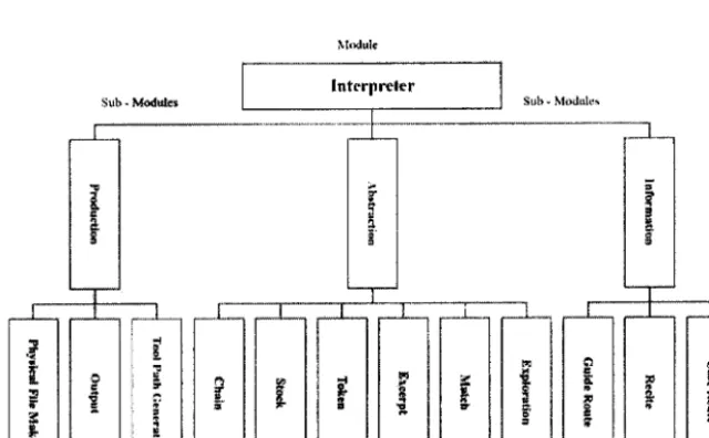
of hardware and software connectivity. The architecture
of
the developed module is composed of three sub-modules -infbrmation, abstraction and production-
which contains various functional blocks such as cese route, recite, guideroute,
exploration, match, excerpt, token, stock, chain,tool path
generator,output
and physicalfle
maker as [image:4.594.125.445.487.685.2]shown
in
Figr"rei.
International Journal of Computer Integra ted ManuJacturing
R
E
?
a.l
H
I
d J
H
;
o €
l3
t:
t-I
I I I I I
I
2.1.
Informution moduleThis sub-module is the initial phase of the interpreter. The purpose
of
this module is to provide the path control for the file uploading, and in the meantimeit
also enables the recite function that reads all the contents of the input file. This module also contains the guide route function which guides the interpreter regarding the startingpoint
of
theinput
file.
Overall, this moduleis
composedof
the caseroute, recite and guide route f,Jnctions blocks. The func-tionality
of
this moduleis
initiatedby
the generationof
path control to get the input source code. After getting the source code path, the next step
of
the recite function isactivated
that
readsthe
complete contentof
the
input source code.At
the endof
this
phase, the guide route function is executed. The roleof
this function is to guidethe
interpreter regardingthe
startingpoint
of
the
code reading. The enablingof
this
function makes the inter-preter to read the code from any line of the input file; by default this function has zero value that indicates the first line of the input code.2.2.
Abstraction moduleThis sub-module
is
the combinationof
both lexical scan and syntax analysis functions. These functions are achievedby
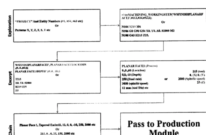
various functional blocks such as exploration, match,excerpt, token, stock and chain. First
ofall,
the exploration function of this module is activated, which searches for thepattems and entities
in
cases of ISO 6983 and ISO 14649,respectively. In the case
ofISO
14649, the starting point is{f |{{)Jlrr"dul l;illq N61rmlill, t*{.*r rt)
()r
lrll.rlr ll{, }, /,, [" lt, t da
titled
'PROJECT'
string;
therefore,the
module
first searchesfor
that string insidethe
'DATA
sectionof
theISO 14649 code. After that, the function starts searching for
the
entity
numbers(i.e.
#2, #4)
inside
the
input
file.However,
in
the G-code case, the function searches for the pattem(X,
Y,Z,
T,
S, F, etc.) inside the input code.After that, all the founded values (entity numbers or patters)
go to the match function, which extracts the entire data
of
searched entity numbersor
pattemsfrom
the input file.After
that, the matched data goesto
the excerpt functionthat minps the data as per the process type, that is, extract names, values, entity numbers, etc.,
in
caseof
ISO 14649.The mining module has different sub-modules for different machining process because in the STEP-NC standard there
are some differences in the placement
of
data for different process. However,in
the caseof
ISO 6983, this functionwill
extract the data values from the matched pattem. At theend of the excerpt function, the token function is executed
that breaks all the extracted data into string tokens. The aim
of
this function is to separate the data as per their type inarrays such as for ISO 14649 (i.e. entity names in one anay, values
in
other anay, entity numbersin
another array, etc') and similarly for ISO 6983 (i.e.X
pattemin
one anay,Y
pattemin
other, etc.). These generated arrays are thenpassed
to
the stock function, which stores all theinforma-tion
insideits
memory.At
the endof
this
module, thefunction
of
lhe chain takes place, which combines all theextracted token data (pattem values
or
valueswith
entity names)into
a
single code and passesto
the production module. Figure 2 shows the functionality of the abstraction module,Pass
to
Production
Module
o o o
c.
x u
I9.,{.5{'}l;
pt,INIil l4{ | r t[.fllt'Jf.Ir, r[ ]l
Or
Hlt
Xn y*.$l@
xlt! tjt
t-a
-
T 6 ! E 6o
J
I
d:+]tACtfi \'lliG-l\'ORtitIGJrf, P{'$3h-lstlPlrI^Rf
d(Et ,'#ilJ'$J{JfllJ)i Or l*l6a 1ilt 116
lttiN{ c0 ct$ (;34 il0. l *. il}. ii,lflllll l\lJ NlW 6d' Itl'i /rl"
ltL.A"\An Sr\fi f, t tlw{q}
0+0{60 tlsafrst lrl lt@t}
d"0rl0{lrtr$!ft} r. $i}O t'1}
tl{l}ud rtrlill qr l0i0$lpkrll*1t!si(} l{Ul l{td{rll{ xl*{'l} 15Xlf'} It uFilxrd lll{} {l{
lbdr trrr{ I,Ti{Frt| Aadmlll.11,0,4.l0riS0' J00t0dr ()r
[image:5.597.105.461.454.688.2]ll$. ll -{'i5' l5{, r$llll *tt
00
Y
..l r
o
J
G
o
'
2.3.
Production moduleThis
sub-moduleis
the
last phaseof
the
interpreter.It
takes
the
outputof
the
abstraction sub-moduleas
aninput. The
initial
functionof
this moduleis
the tool path generator that takes the combined codeofthe
abstraction module as an input and generatestool
pathsby
utilising the values of the combined code. The tool path generator function contains.facing,drilling
and pocketing tool path generator sub-functional blocks.The
activationof
sub-functionis
recognisedfrom
the
process names, which are includedin
the
combined codeof
the
abstraction module. After the tool path generation, the module passesthe data to the output function that
will
transfer the data to the relative hardware parts of the CNC machine controller. The output function plays a key role in passing the data to the machine controller hardware partsin
the correct way (i.e. axis values go to the respectiveX,
Yand Z axis servo/stepper motors, tool values go to the tool changer, etc.).
At
the same time, this module is also able to generate physi-cal output
file in
user-defined structureof
.txt
and .xml formats by meansof
the physicalfile
generator function. The generated files can be usedin
any typeof
PC-based open architecture CNC machine systems.3.
Algorithm
designThe developed module
is
composedof
two
algorithms becausethe ISO
6983 data interfacemodel
is
a
line-based languageand
can
be
executedline
by
line. Whereas the ISO 14649 is intended to be executed work-ingstepby
workingstep.The
STEP-NC algorithm must read the complete programfirst
and able to generate tool paths (Krarner et al. 2006). These algorithms utilise var-ious functional blocksfor
the
interpretationof
the
ISO data interface modules.3.1.
Algorithm designfor
ISO
14649 interpretation The algorithmof
ISO 14649 interpretation startswith
the case route function that provides the pathto
load
ISO 14649 part2l
file.
Then the recite functionis
executed, which reads the complete contentof
the inputfile.
This function has a decision module that looks inside the input file and makes decisions regarding the stahrs of file.If
the inputfile
does not contain anyISO
14649 data, the deci-sion model sends the signal towards theeror
message.If
it
contains data, the model passes thefile
to
the guideroute function The aim
of
this
function
is to
provideaccess to read the input
file
from any point.After the selection
of
line index, the data passes to theexploration function.
This
functionfirst
searchesfor
the'PROJECT' string inside the input code, followed
by
the search for entity numben (#1,#2, etc.) inside the input file, While readine for the first timeif
the function has not foundthe 'PROJECT' string
or
entity number,it
will
pass thesignals to error message. In other cases, the founded entity numbers are passed
to
the match function that reads theinput
file
and searches for the entities number values. The outputof
this functionis
the complete dataof
the entitynumber
(i.e. #54
=
MACHINING_WORKINGSTEP('WSFINISHPLANARFACEI"
#113,#34,#53,$)), thenthat
datais
enteredinto
the
excerpt function that firstsearches
for
the machining process and then extracts thedata as per process types. This function is linked with the
process names library that guides the interpreter regarding the data mining structure.
In
the STEP-NC file, eachpro-cess has some difference
in
a seriesof
informationplace-ments because different processes contain different amounts
of
information.After
that, the token functionis
executedthat generates the string tokens
of
the extracted data. The generated stringis
storedin
the intemal memoryof
thesystem
with
the help
of
the stock function.The
tokenfunction divides the data into separate anays such as entity numbers anay, process ntunes alray, locations values anay, depth values array, tolerance values array, etc.
At
the end,the token function passes
all
the informationto
the stock function that saves all the data in the intemal memory. After saving,the
function recallsthe
exploration function to search for entity numbers inside all the stocked anays.At
this
stage, the algorithm makesa
decision.If
the entitynumber
is
found,
it
recalls
all
the
processes again.However, when
no
entity nurnberis
foundin
the storeddata arrays, the function parses the data to the chain fitnc-tion that combines all the data into a single code and passes
to the production module.
In this module, the combined code is passed to the tool path generator function that utilises all the information
of
the combined code and generates
tool
pathsfor
specific processes. This functionis
also connected to the processname library that guides the function regarding the
selec-tion
of
sub-tool path generation modules as per specificprocess types (i.e. facing, drilling, pocket, etc.). After the tool path generation, the output function is executed that parses the information to the hardware parts
of
the CNC machine.At
the same time, this module is able to generatethe output physical
file
in
.txt
and.xml
formats as per user-defined structurewith
thehelp
of
the physicalfile
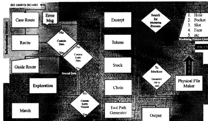
maker funclion. Figure 3 shows theflow
chart of the ISO 14649algorithm
design, whereas Figure4
shows thefunctionality of the algorithm.
3,2.
ISO
6983 interpretation algorithm designThis
algorithmis
also composedof
three sub-modules:information, abstraction and productior. The functionality
of the first and last modules is the same as discussed in the
ISO
14649 interpret algorithm design. Whereas there isonly a
slight differencein
the abstraction module' ThisInternational Journal of Computer Integrated Manufacturing
a]
oo
Y
al
d
F
oe
-l
v
o
[image:7.595.112.456.82.283.2]F
Figure
3.
Flow chart of the ISO 14649 algorithm design.Figure
4.
Functionality of the ISO 14649 algorithm.for
pattems (i.e.X,
Y,
Z,
F,
S,T,
etc.) inside the input code. This function has a decision module that passes tl'redata to error message
if
no pattem is found. However, in other cases, the data passesto
the match, excerpt, token,stock and chain functions step by step. The match function of the algorithm scans the input
file
for pattem values (i.e. X25, Y30,Z-5,
etc.). These valueswill
be extracted byexcerpt function and parsed
to
the token function. This function breaks the extracted data into token strings in thec.l
oo
9
at
d r
o
(.) P
J
cd E
v
(.)
Figure
5.
Functionality of the ISO 6983 algorithm.intemal memory
of
the system. Then that saved data isrecited
by
the chain function that combinesall
the datainto
single code and parsesthe
combined codeto
the production module. That combined code provides a shop floor editing functionalities for position, tool, spindle, feed rate, etc., data. The functionalityof
the ISO 6983 algo-rithm is shownin
Figure 5,4.
Graphical user interfacesThe GUIs
of
a
developed moduleis
composedof
fourtabs'. main, shop
fioor
editon details and setting. The main tab contains case route functionfrom
where the system getsthe
input
code.The ISO
14649GUI
shows the complete contentsof
the
input
file with
headers data,project name data, workpiece data, cutting
tool
data andmachining process data. The main screen
of
GUI
showsall
the dataof
header, project name, workpiece, cutting tool and machining processesin
different sections, so thata user can easily understand the content
ofthe
input code.Whereas the ISO 6983
GUI
main page shows the inputfile
path control,input ISO
6983 code and interpreted code.The
shopfloor
editor
tab
showsthe
combined codewith
tool
pathsin
separatefields
for
easy under-standingand
modificationsin
information
offiine
orwhile
machining.This tab
showsall
the
information regarding positions,tool,
spindle, feedrate,
tolerance, etc.,in
separate columns.The
detailstab
provides the completeinformation
regardingposition,
tool,
setup,workpiece, processes, tolerances, locations, depths, etc.,
in
different sectionswith
pattems or entity numbers, pat-temsor
entity names, values, etc., and also provides anaccess
for
data modificationoffiine or while
machining. The last tab is of settings that provide access to the input and output setting of thefile.
For input setting,it
has the guide route function, whereasfor
output settingit
has aphysical
file
maker function, where the user can set thesffucture of the output
file
as per the required structureof
the CNC
machinein
.txt
and
.xml
formats. The inputsetting
is to
guidethe
interpreter regarding the starting point (the point from which the interpreter starts readingthe input
code).By
defaultthis
hasa
valueof 0
thatindicates the
first line of
the input code. Output settings have three steps: thefirst
stepis for
selecting the outputfile
format (.txt or .xml), the second step is for format anddelimiter settings for text file format and the last step is for
.xml
output
settingsusing
XML
encoding controller. Figure 6 shows the snapshots of the GUIs.5.
Working
principleThe developed module is able to work with cunent CAD/
CAM
systems.In
the caseof
ISO
14649, the working principle startswith
uploadingof
the STEP part2l
file. There arefew
platforms availablefor
the generationof
STEP part
2l
file. In
this
study,GEN-MILL
generator (Yusof, Kassim, and Zamrt Tan20ll),
STLDeveloper andSTEP Tools online platforms (http;//www.steptools.com)
are used. Whereas in case of ISO 6983, the working cycle starts
with the CAD
designwhich
then utilises CAM softwarefor
the generationof
ISO 6983 code.After
file uploading, the system performs the functionsof
the infor-mation module first, abstraction module second and pro-duction module third as shownin
Figure 7.6,
Experimental studyIn this study, various experiments have been perfonned for
the
testing and validationof
the
developed interpreter. Twoof
these are discussedin
this
section: oneis
basedInternati onal Journal of C omputer Integra ted Manufacturin g
V)
s
E
\o
f9
o
tl
w
(}\
@
(JJ
.D
ro
6
TD
o
3
C
c-.1
oo
s
al c! ro
J
;
o
[image:9.593.114.460.79.466.2]d Figure
6.
Snapshots of the developed rnodule GUIsFigure
7.
Working principle of the developed module.6,1.
Experiment based onISO
14649 interpretation In this study, the manufacturing ofISO
14649 exampleI
part has been carried out
by
using the developed modulewith
the OAC CNC system (Yusof andLatif
2013). Theexperiment started
with
the generationof
STEP parl2l
file
by using STEP Tools online platform.After
that, thefile
is uploaded into the developed interpretation module.Before performing the interpretation operation, the setting
l0
@
o
@ .A
u t(,
a.l 'r
oo
*
c.l
o o
-.1
v
q)
Figure
8.
Experimental serup of the developed module.of
the outputfile is
carriedout
as per the requirementsfrom
the setting tabof
the
developed module.In
thisexperiment, the output code is fonnatted as floating point number
(%0
with
comma(,)
delimitation.After
all
set-tings have been done the example
I
part2l
file
is
exe-cuted by the developed interpreter and output physical filein
.fxt
formatis
generated.Then the
generatedfile
isuploaded
in
theOAC CNC
systemvia
USB. The OAC system gets the information from the interpreted code andperformed operations for the production of part, as shown in Figure 8.
6,2.
Experiment based onISO
6983 interpretation This experiment is to write the letters U, T,H
andM
on apiece
of
wax materialby
using culrentCAD/CAM
sys-tem, the developed interpreter and open architecture CNC machine (Yusof and
Latif
2013).The
experiment startswith
the design process,in
whichU,
T,H
andM
letterswere
designedby
using CAD/CAM
software.
After designing,CAM
machine
featuresare given
to
the designerin
order to generate the ISO 6983 code and the generated code is savedin
.txt format by using theCAM
software code editor. Once the ISO 6983 code
is
gener-ated, the next stepof
uploading the code into thedevel-oped
interpretationmodule
was
carried
out.
Before performing the interpretation operation, the settingof
the output file is carried out as per the requirements from the setting tabof
the developed module.In
this experiment, the output code is formatted as floating point number (%f)with
cornma (,) delimitation.After all
settings have beendone, the code is executed and the output file saved in .txt format. Then, finally, the interpreted code is transferred to an
OAC
CNC machine and operations are performed asshown in Figure 8.
7,
Discussion, conclusion andfuture
worksIn this papeq an interpretation module has been developed for PC-based open architecture CNC control system that is
able to interpret the ISO 14649 part
2l
and ISO 6983 datainterface model information as per the required structure
of
the CNC machine. The moduleis
composedof
three sub-modules:infonnation, abstraction
and production. These modules works on the basisof
the variousfunc-tional blocks such as
caseroute,
recite,guide
route,exploration,
match,
excerpt, token,stock, chain,
tool path generator, output andphysicalfile
maker. The devel-oped module also provides data editing facilities whileworking or offiine
andis
also ableto
generate physicalfile
outputin
.txt
and.xml
formats as per user-defined strucrure,The module
is
designedin
NI
LabVIEW andis of
open nature
that
welcomes contributionsfrom
different sourcesto
communicatein
termsof
software(VB,
C1-+,C#, JAVA,
MATLAB,
SolidWorks, etc.) and hardware to enablemonitoring,
inspection,report
generation, etc.,facilities. In the ISO 6983 case, these facilities are limited because
of
low-level data: however,ISO
14649 contains high-level data and can be a strong competitor to replace the G-code. The STEP-NC interpreter is easy to develop comparedwith
the G-code because the G-code requiresInternational Journal of Computer Integrated Manufacturing
ll
(\
oo
6t
c!
-
o oJ
v
o
Cn
post-processors
for
specific
machines.The
STEP-NC interpreter can be easily implemented on PC-based CNC systems and a single setof
algorithm can enableall
the featuresof
highJevel data interfacemodel
and makesCNC more open, flexible, intelligent, etc.
This
modulecan make
life
easyfor
the
users.It
extracts the complete data from high-level and lowJevel codes and shows an easy way on GUIs.
It
showsall
the extracted data of set-up, workpiece, coordinates, locations, depth, tool, tolerance, etc.,into
separate portions to pro-vide an easy understanding to the user about the contentof
the input
file
and also provides optionsfor
easy datamodification as per the requirements.
This
systemis of
low cost compared to commercial systems and can play an
important role in the development
of
small industries andshop floor CNC users. The majot advantage of this system
is
thatit
can be usedto
convertold
manually operated machines into automatic units. The system can be easily implemented on any system without any hardware or soft-ware requirements. Currently, the system has been imple-mentedon
Windows
environment-basedCNC
system.This
study also showsthe
validationof
the
developedinterpretation module
in
experimentalwork.
There are a numberof
successful experiments performedwith
the developed module that shows good accuracy and perfor-mance with the OAC CNC system.Overall, this study contributes in the field of interpreter by introducing a new method of ISO data interface models interpretation and utilisation of LabVIEW platform in the development
of
STEP-compliant system. The systeur pro-vides a platform to enable modern rnanufacturing facilities like shop floor editing, inspection, monitoring, reportgen-eration, etc.,
in
current
and
future
manufacfuring environment.In
future, the interpreter can be updatedby
enabling universal interpretation for ISO 6983 like Guo et al. (2008, 2012), G-codeto
STEP-NC or vice versa translation like Shin, Suh, and Stroud (2007) andX.
Zhang et al. (2013), implementon Linux CNC
environmentto
enable RT environment like Ji,Li,
and Wang (2008) and Starove5ki et al. (2009), ISO 14649 part 28 interpretation, intelligent and accurate tool path generations, monitoring and inspec-tion GUIs development, simulation, more processes inter-pretation and tool path generation, etc. Overall, the main aimof
this researchis to
develop an all-in-one platform for the CNC machine.Acknowledgement
The authors thank Dr. David Loffredo, Vice President of STEP
Tools Inc.. and Dr. Nazareno de Oliveira Pacheco from the Universidade Federal Santa Catarina for their help and guidance.
Disclosure statement
No notential conflict of interest was reported by the authors.
Funding
This work was supported by the Malaysian Govemment under
Science
fund
S02l
(MOSTI)and
Malaysian IntemationalScholarship (MIS) under the Ministry
of
Education (MOE) Malaysia.References
Asato, O., E. Kato, R. Inamasu, and A. Porto. 2002. "Analysis of
Open CNC Architecture for Machine Tools." Journal of the
Brazilian Society of Mechanical Sciences 24 (3): 208-212.
doi:1 0. I 590/S0 I 00-73 862002000300009.
Bishop, R.
H.
2009. LabVIEW 2009 Student Edilion. Upper Saddle River, NJ: Prentice Hall Press.Calabrese, F., and G. Celentano. 2007. "Design and Realization
of
a
STEP-NC Compliant CNC Embedded Controller."IEEE Conference on Emerging Technologies and Factory
Automation,
2007. ETFA,
Patras, September 25-28,1010-1017. IEEE.
da Rocha, P., R. Diogne De Silva E Souza, and M. E. De Lima Tostes. 2010. "Prototype CNC Machine Design." 2010 gth IEEEAAS Intemational Conference on Industry Applications
(INDUSCON), Sao Paulo, November 8-10,
l-5.
IEEE. Ekkachai, K., U. Komin, W. Chaopramualkul, A. Tantaworrasilp,P. Kwansud, P. Seekhao, T. Leelasawassuk, K. Tanta-Ngai, and K. Tungpimolrut. 2009. "Design and Development of an
Open Architecture CNC Controller
for Milling
MachineRetrofitting." ICCAS-SICE, Fukuoka,
August
18-21, s629-s6J2. IEEE.Elliott, C., V. Vijayakumar, W. Zink, and
R.
Hansen. 2007."National
InstrumentsLabview:
A
ProgrammingEnvironment
for
Laboratory Automation
and Measurement." Joumal oJ the Association ./br LaboratoryAutomation | 2 (1): 11 -24. doi: I 0. 1 0 I 6/j ja1a.2006.0'7 .0 12.
Ertell, G. G. 1969. Numerical Control. New York: Wiley. Feeney, A. 8.2002. "The STEP Modular Architecture." Journal
oJ'Computing and In/brmation Science in Engineering 2 (2)'.
132-1.35. doi: 10. I I I 5/1. I 5 I 1 520.
Feeney,
A.
B., T. Kramer, F. Proctor,M.
Hardwick, and D.Loffredo.
2003.
"STEP-NC Implementation-Arm orAIM?" ISO T24 STEP-Manufacturing Meeting, San Diego,
CA, March. ASME.
Groover,
M.
P
2007. Autornation, Prcduction Sltstems, andC onrputer- Integrated M anulitctur ing. U pper Saddle River, NJ: Prentice Hall Press.
Guo, X., Y. Liu, D. Du, K. Yamazaki, and M. Fujishima. 2012.
"A
Universal NC Program Processor Design and PrototypeImplementation
for
CNC
Systems." The International Journal of Advanced Mandacturing Technology 60 (5-8):561-57 5. doi: I 0. I 007/s00 I 70-01 I -36 I 8-6.
Guo, X., Y. Liu, K. Yamazaki, K. Kashihara, and M. Fujishima. 2008. "A Study
ofA
Universal NC Program Processor for ACNC
System." The International Jtturnalof
AdvancedManufitcturing Technology
36 (7-8):
738-745.doi: 10. I 007/s00 1 70-006-0890-y.
Hamilton,
K.,
J.-Y.
Hascoet,and
M.
Rauch.
2014."Implementing STEP-NC: Exploring Possibilities
for
theFuture
of
Advanced
Manufacturing."In
Modern Mechanical Engineering, 199-239. Berlin: Springer.Hardwick, M., Y. F. Zhao,F. M. Proctor, A. Nassehi, X. Xu, S.
Venkatesh, D. Odendahl, L. Xu, M. Hedlind, M. Lundgren,
L. Maggiano, D. Loffredo, J. Fritz, B. Olsson, J. Garrido,
c-.1 00
Y
m c.l c) q) J cdv
C) BAdvanced Manulacturing Technologt 68 (5-8): 1023-1037. doi:10. I 007/s00 1 70-01 3-4894-0.
Houshmand, M., and O. F. Valilai. 2012. "LAYMOD: A Layered
and Modular Platform
tbr
Cax Product Data Integration Based on the Modular Architectureof
the Standard for Exchangeof
Product Data." International Journalof
Computer Integrated Manufacturing
25
(6):
473487.doi:10.1080/095 I 192X.20I 1.646308.
ISO 6983-1. 1982. Numerical Control
of
Machines-ProgramFormat and Definition
of
Addre.ss lllords-PartI:
Dala Format.for
Positioning,Line and
Contouring ControlSystems. Geneva: ISO.
$O,
C.
1991. "10303-1: Product Data Representation and Exchange-Partl:
Overview and Fundamental Principles."In TC, 184. Geneva: ISO.
ISO,
I.
1994. 10303-1. Industrisl Automation Sltstems and I nte grati on-Product Dat a Reples entation and Exchange-Parl,
/.
Geneva: ISO.ISO,
T.
1994. 184/SC4, ISO 1030i-ll:
1994 Industrial Automation Systemsand
Integration-Product DataRepresentation
and
Exchange-Part Il:
DescriptionMethods:
The
EXPRESS Language Refbrence Manual. Geneva: ISO.Ji, H.,
Y
Li,
and J. Wang. 2008."A
Software Oriented CNC System Based on Linux/Rtlinux." The International Journa!of Advanced Manufocnting Technologv 39 (3-4): 29 l-30 I . doi : I 0. 1 007/s00 1 7 0-00"1 - | 2 | 6-4.
Khanna, A., A. Kumar, A. Bhatnagar, R. Tyagi, and S. Srivastava.
2013. "Low-Cost Production
CNC
System." 2013 7thIntemational Conference on lntelligent Systems and Control OSCO), Coimbatore, January 4-5, 523-528. IEEE.
Kramer, T. R., F. Proctor, X. Xu, and J. Michaloski. 2006.
"Run-Time
Interpretationof
STEP-NC: Implementation andPerfonnance."
International
Journal
of
ComputerIntegrated Manufachring 19 (6): 495-507. doi:10.1080/ 09511920600622056.
Krzic, P.,
A.
Stoic, and J. Kopac. 2009. "STEP-NC:A
NewProgramming Code
for
theCNC
Machines." StrojniikiVestnik 55 (6): 406417.
LabVIEW,
F.
2009. National Instnrments LabVIEW FPGA. Austin, TX: Austin Press.Lee, W., Y.-B. Bang,
M.
Ryou, W. Kwon, and H. Jee. 2006. "Development of a PC-Based Milling Machine Operated bySTEP-NC
in
XML
Format." Internstional Journal of'Computer Integrated Manufacturing
l9
(6):
593-602.doi: I 0. I 080/095 119206006236'7 4.
Li, M.-S., and F.-F. Zhang. 2010. "The Research of Embedded
CNC System Component." 2010 Intemational Conference
on
ComputerApplication
and
System
Modeling (ICCASM), Vol. 7, North Universityof
China, Taiyuan, October 2214, V 7 -601-V607-604. IEEE.Liang, S. Y., R. L. Hecker, and R. G. Landers. 2004. "Machining
Process Monitoring and Control: The State-Of-The-Art."
Journal
o/
Manufacturing Science and Engineering 126(2): 297-310. doi:10.1 1 I 5/1.1707035.
Ma, X.-8.,
Z.-Y. Han,Y.-2.
Wang, and H.-Y.Fu.
2007."Development of a PC-Based Open Architecture
Software-CNC System," Chinese Journal
of
Aeronautics20
(3):27 2_28 l . doi : 1 0. I 0 I 6i S 1 0 00 -9 3 6 | (07 )60044-2.
Minhat, M., V. Vyatkin, X. Xu, S. Wong, and Z. Al-Bayaa,2009. "A Novel Open CNC Architecture Based on STEP-NC Data
Model and
IEC
61499 Function Blocks." Robotics andComputer-lntegrated Manufachring
25
(3):
560-569. doi: I 0. l0l 6/j.rcim.2008.03.02 1.Mori, M., K. Yamazaki, M. Fujishima, J. Liu, and N. Furukawa. 2001.
"A
Study on Development ofan Open Servo Systemfor
Intelligent Controlof
A
CNC Machine Tool." C/RPAnnals-Manufacturing Technologt
50 (l):
247-250.doi: I 0. I 0 I 6/50007-8506(07)62 1 I 5-5.
Newman, S.,
R.
Allen, andR.
Rosso Jr. 2003. "CAD/CAMSolutions
for
STEP-CornpliantCNC
Manufacture."Intem ational J oum al oJ Computer Integrated ManuJacturing
I 6 (7-8): 590-597. doi: 1 0. 1080/095 I 19203 1 0001 1s688.
Newman. S., and A. Nassehi. 2007. "Universal Manufacturing Platform for CNC Machining." CIRP Annals-Manufitcturing
Techno kt gt 56
(l):
459462. doi: I 0. I 0 I 6/j'cirp.2007.05. 1 I 0. Pabolu,V. K.,
and
S.
Srinivas.2010. "Design
andhnplementation
of
a
Three Dinrensional CNC Machine."International
Journal
on
Computer Science andEngineering 2 (8): 2567 -257 0.
Pacheco, N. D. O., E. Harbs, R. S. Rosso Jr, M. D. S. Hounsell, and J. C. E. Feneira. 2012. "Application of The Step-NC Standard
in
a
Computer Numerical Controlled Machining Device." ABCM Symposium Series in Mechatonics 5: 7 13-723Park, S., S.-H. Kim, and H. Cho. 2006. "Kemel Software for Efficiently Building, Re-Configuring, and Distributing an Open
CNC
Controller." The Internalional Journalof
Advanced Manufacturing Technologt 27 (7-8): 788-796.
doi: 1 0. I 007/s00 17 0-004-2243 -2.
Ramesh, R., S. Jyothirmai, and K. Lavanya. 2013. "Intelligent
Autonration of Design and Manufacturing in Machine Tools
Using an Open Architecture Motion Controller." Journal of'
Manufacturing Systems
32
(l):
248-259. doi:10.1016/j.jnsy.20l2.l L004.
Ramesh, R., A. Poo, and Intelligent. 2009. "Ethemet Based Open
Architecture Control System
for
Machine Tools'" IEEEIntemational Conference
on
Intelligent Computing andIntelligent Systems, Vol.
2,
Shanghai, November 20-22'612-6'16. IEEE.
Safaieh, M.,
A.
Nassehi, and S. T. Newman. 2013."A
Novel Methodology for Cross-Technology Interoperability in CNCMachining."
Rohotics
and
ComputerJntegrated Manu f it ctu r in g 29 (3): 7 9-87 . doi : I 0. I 0 I 6/j.rc im 20 12 04.0 1 6.Shin, S.-J., S.-H. Suh, and I. Stroud. 2007. "Reincamation of
G-Code Based Part Programs
into
STEP-NCfor
TumingApplications." Computer-Aided Design
39 (1):
1-16. doi: I 0. I 0 I 6/j.cad.2006.08.005.Starove5ki, T.,
D.
Brezak, T. Udiljak, andD.
Majetii. 2009'"Implementation
of
a
Linux-Based CNC Open ControlSystem."
lnternational
Conferenceon
Production Engineering, Biograd, June 17-20.Stenerson,
J.
S., andK.
Curan. 2005. Computer NumericalContt'ol: Operation
and
Programming. Upper Saddle River, NJ: Prentice-Hall.Suh. S.-H.. and S.-U. Cheon. 2002.
"A
Frameworkfor
an IntelligentCNC and Data Model."
The International Journal o/ Advanced Manufacturing Technologt 19 (10):72'7 -7 35. doi: 1 0. l 007/s00 1 700200083.
Suh, S.-H., J.-H. Cho, and H.-D. Hong. 2002. "On the Architecture of Intelligent STEP-Compliant CNC." International Journal oJ'
Computer Integrated ManuJitcaring
15
(2):
168-177 . doi:1 0, I 080/095 1 1 9201 I 0056541 .Talavage, J. 1987. Flexible Maurfacturing Systems in Practice: Design: Analysis and Simulation Vol. 26' Boca Raton, FL: CRC Press.
Vichare, P. A. Nassehi, S. Kumar, and S. T. Newman' 2009, "A Unified Manufacturing Resource Model
for
RepresentingComputer-rl t
International Journal of Computer Integrated Manufacturing t3
Integrated Manufacturing 25 (6): 999-1 007. doi: I 0. I 0 I 6/j.
rcim.2009.04.0l4.
Wang, H., X. Xu, and J. Des Tedford. 2007. "An Adaptable CNC
System Based
on
STEP-NCand
Function Blocks." International Journal oJ Production Research45
(17):3 809-3 829. doi: I 0. I 080/00207 540600'l'/ 407 5.
Wang,
T.,
Q.
Liu,
andL.
Wang. 2010."An
RTOS-Based Embedded CNC System." 2010 International Conferenceon
Computer, Mechatronics,Control
and
ElectronicEngineering (CMCE), TBD, Vol.
2,
Changchun, August24-26,33-36. IEEE.
Weidong, Y, and G. Zhanbiao.20l0. "An Open CNC Controller Based on Labview Software." 2010 International Conference on Computer Application and System Modeling (ICCASM), North University of China, Vol. 4, Taiyuan, October 22-24, v4470-Y474-479. IEEE.
Xiao, S., D. Li, Y. Lai, J. Wan, and S. Feng. 2007. "An Open Architecture Numerical Control System Based on Windows
CE."
IEEE
Intemational Conferenceon
Controland Automation, 200'1, Guangzhou,
May
3G-June 1,1237-1240, LEEE.
Xu, X., and Q. He. 2004. "Striving for a Total Integration of CAD, CAPB CAM and CNC." Robotics and
Computer-htegrated Manufacturing 20
(2):
101-109. doi:10.1016/j. rcim.2003.08.003.Xu, X., and S. Newman. 2006. "Making CNC Machine Tools More Open, Interoperable and Intelligent-A Review of the
Technologies." Computers
in
Industry 57(2):
141-152. doi: I 0. I 0 l6lj.compind.2005.06.002.Yusof, Y.,
N. D.
Kassim, andN.
Z. Zamri Tan.20ll.
"The Development of a New STEP-NC Code Generator(GEN-MILL)."
Internationul Jcturnal o/' Computer IntegratedMarufucturing
24 (2):
126-134.
doi:10.1080/095 1 I 92X.201 0.53 1289.
Yusoi Y., and K. Latif, 2013. "Frame Work of LV-UTHM: An ISO 14649 Based Open Control System for CNC Milling
Machine." Applied Mechanics and Materials 330: 619-623. doi: 1 0.4028/www.scientifi c.net/AMM.3 30.6 I 9.
Zhanbiao, G. 2010. "An Open CNC Controller Based on Labview
Software."
In
2010 International Conference on ComputerApplication and System Modeling (ICCASM 2010), Vol. 4, North University of China, Taiyuan, October 22-24. Zhang, X., A. Nassehi,
M.
Safaieh, and S. T. Newman. 2013.Process Comprehension
for
Shopfloor ManufacturingKnowledge Reuse. International Journal
of
Production Research5\
(23-24):l-15.
Zhang,Y., X. Xu, X. Bai, and Y. Liu 2010. "Understanding the
STEP-NC Data Model for Computer Nunrerical Control."
2010 Znd Intemational Conference on Advanced Computer Control (ICACC), Vol. 1, Shenyand, March2T-29,300-304.
IEEE.
Zheng, J,, W. Zhao, and Z. Li. 2005. "Open EDM CNC System Based on RT Linux." Computer Integrated Manufacturing Systems-Beijing
l1
(8): I179.a.l
oo
:q a.) c.l r
C)
o J
I
;
()