AIR BREAKDOWN CHARACTERISTICS IN ROD-PLANE AND SPHERE-PLANE ELECTRODE CONFIGURATION UNDER LIGHTNING IMPULSE
HAFIZAH BINTI NOR AZMUDDIN
A project report submitted in partial fulfillment of the requirement for the award of the
Master of Electrical Engineering
Faculty of Electrical and Electronic Engineering Universiti Tun Hussein Onn Malaysia
VI
ABSTRACT
VII
ABSTRAK
VIII
TABLE OF CONTENTS
TITLE I
DECLARATION II
DEDICATION IV
ACKNOWLEDGEMENT V
ABSTRACT VI
CONTENTS VIII
LIST OF TABLES XII
LIST OF FIGURES XIII
LIST OF SYMBOLS AND ABBREVIATIONS XVI
CHAPTER 1 INTRODUCTION 1
1.1 Project Background 1
1.2 Problem statement 2
1.3 Objective Project 3
1.4 Project Scope 3
1.5 Organization of Thesis 4
CHAPTER 2 LIGHTNING & AIR BREAKDOWN: A REVIEW 5
2.1 Introduction 5
2.2 Lightning Impulse Voltage 5
2.3 Air Breakdown Mechanism 6
2.3.1 Townsend‟s Mechanism 7
2.3.2 Streamer Theory 9
2.3.2.1 Streamer process 9
IX
2.5 Capacitive Divider 12
2.6 Electrode Arrangement for Measurement of Breakdown Voltage 13
2.7 Finite Element Method Magnetic 13
2.8 Previous Related Work 14
2.8.1 Summary of previous related works 17
CHAPTER 3 LIGHTNING IMPULSE TEST PROCEDURE & 19
SIMULATION MODEL
3.1 Introduction 19
3.2 Method for Generation of Lightning Impulse 19 3.3 Experimental Setup for Measurement of Lightning Impulse Voltage20
3.3.1 Equipment in the Generation of Impulse Voltages Circuit 21
3.3.1.1 Control Desk 21
3.3.1.2 Test Transformer 22
3.3.1.3 Silicon Rectifier 23
3.3.1.4 Smoothing Capacitor 23
3.3.1.5 Impulse voltmeter (digital display) 24
3.3.1.6 Low Voltage Divider 24
3.3.1.7Load Capacitor 25
3.3.1.8 Insulating Rod 25
3.3.1.9 Charging Resistor 26
3.3.1.10 Wave-front Resistor 26
3.3.1.11 Wave-tail Resistor 26
3.3.1.12 Sphere Gap 27
3.3.1.13 Drive for Sphere Gap 27
3.3.1.14 Earthing Switch, Electrically Operated 28
3.3.1.15 Electrode 28
3.3.1.16 Earthing Rod 29
3.3.1.17 Connecting Cup, Aluminium 29
3.3.1.18 Floor Pedestal 29
X
3.3.1.20 Spacer Bar 30
3.3.1.21 Measuring Spark Gap 31
3.4 Single-stage Impulse Voltage Generator 32
3.5 50% Breakdown Voltage (U50) 33
3.6 Finite Element Method Magnetic 35
3.6.1 Create Model 36
3.6.2 Assign Boundary Condition 37
3.6.3 Mesh 38
3.6.4 Solve Setting 39
CHAPTER 4 BREAKDOWN PROPERTIES OF AIR UNDER 40
LIGHTNING IMPULSE: EFFECT OF ELECTRIC
GEOMETRY AND GAP LENGTH
4.1 Introduction 40
4.2 Lightning Impulse Voltage Waveform 40
4.3 Simulation of Electric Field, Emax using FEMM Software 42
4.3.1 Mesh 43
4.3.2 Voltage Density 44
4.3.3 Field Intensity |E| 45
4.3.4 Contour (Equipotential lines) 46
4.3.5 Vector Plot (Electric Field Intensity, |E|) 47
4.3.6 Contour & Vector 47
4.4 Graph of the Voltage, V and Magnitude of Field Intensity, |E| 49
4.4.1 Rod to Plane Configuration 50
4.4.2 Sphere to Plane Configuration 52
4.5 Result for breakdown voltage U50 (kV), electric field (kV/cm) 54 and field utilization factor (ƞ) for Rod to Plane and Sphere to Plane 4.5.1 The Relationship of U50, Emax and Field Utilization Factor 55
with the Gap between the Two Electrodes
XI
CHAPTER 5 GENERAL CONCLUSION & FUTURE WORK 61
5.1 Conclusion 61
5.2 Recommendation 62
XII
LIST OF TABLES
2.1 Tolerance of standard lightning impulse voltage 6
2.2 Summary of previous related works 17
3.1 Description the button for control board 22
4.1 Emax (kV/cm) for rod to plane electrode configuration 43 4.2 Emax (kV/cm) for sphere to plane electrode configuration 43 4.3 Result for sphere to plane electrode configuration 54 4.4 Result for sphere to plane electrode configuration 55 4.5 Result of the field utilization factor for rod to plane and 57
XIII
LIST OF FIGURES
2.1 Standard lightning impulse voltage waveform 6
2.2 Arrangement for Townsend‟s mechanism 7
2.3 Townsend‟s mechanism process 8
2.4 Streamer mechanism 9
2.5 Formation of secondary avalanches due to photo-ionization 10
2.6 Sparkover 11
2.7 Flashover 11
2.8 Capacitor divider connected in series 12
2.9 Types of electrodes 13
3.1 Method to obtain lightning impulse 20
3.2 Experimental setup lightning impulse voltage 21 3.3 Block diagram for lightning impulse circuit 21
3.4 HV 9103 Control desk 22
3.5 HV 9105 Test transformer 23
3.6 HV 9111 Silicon rectifier 23
3.7 HV 9112 Smoothing capacitor 24
3.8 HV 9152 Impulse voltmeter (digital display) 24
3.9 HV 9130 Low voltage divider 25
3.10 HV 9120 Load capacitor 25
3.11 HV 9124 Insulating Rod 25
3.12 HV 9121 Charging resistor 26
3.13 HV 9122 Wave-front resistor 26
XIV
3.15 HV 9125 Sphere gap 27
3.16 HV 9126 Drive for sphere gap 27
3.17 HV 9114 Earthing switch, electrically operated 28
3.18 HV 9138 Electrode 28
3.19 HV 9107 Earthing rod 29
3.20 HV 9109 Connecting cup, aluminium 29
3.21 HV 9110 Floor pedestal 30
3.22 HV 9108 Connecting rod, aluminium 30
3.23 HV 9119 Spacer bar 30
3.24 HV 9133 Measuring spark gap 31
3.25 Different type of electrodes 31
3.26 Single stage impulse voltage generator block diagram 32
3.27 Single stage impulse voltage test setup 33
3.28 Method to obtained U50 by using up and down method 34 3.29 Method to obtain the electric field using FEMM 35
3.30 Example to create the model 36
3.31 Boundary condition setting 37
3.32 Mesh 38
3.33 The value of the electric field 39
3.34 The value of the voltage 39
4.1 Lightning impulse waveform for tail time, T2 41 4.2 Lightning impulse waveform for front time, T1 41
4.3 Lightning impulse voltage chopped 42
4.4 Mesh for rod to plane and sphere to plane 44 4.5 Voltage density for rod to plane and sphere to plane 45 4.6 Field intensity for rod to plane and sphere to plane 46 4.7 Contour (Equipotential lines) for rod to plane and 46
sphere to plane
XV
sphere to plane
4.11 The legend of voltage density 49
4.12 The point a-b to get the voltage, V for rod to plane 50 4.13 The point c-d to get the field intensity, |E| for rod to plane 50 4.14 The point a-b to generate the voltage, V graph 51 4.15 The point c-d to get the field intensity, |E| graph 51 4.16 The point a-b to get the voltage, V for sphere to plane 52 4.17 The point c-d to get the field intensity, |E| for sphere to plane52 4.18 The point a-b to generate the voltage, V graph 53 4.19 The point c-d to get the field intensity, |E| graph 53 4.20 The gap (cm) versus U50 (kV) between the rod to plane 53
and sphere to plane
4.21 The gap (cm) versus Emax (kV/cm) between the rod to 56 plane and sphere to plane.
4.22 The gap (cm) versus field utilization factor (ƞ) between 57 the rod to plane and sphere to plane.
4.23 U50 (kV) versus field utilization factor (ƞ) for rod to plane 58 4.24 U50 (kV) versus field utilization factor (ƞ) for sphere 59
to plane
4.25 Emax (kV/cm) versus field utilization factor (ƞ) for rod plane 60 4.26 Emax (kV/cm) versus field utilization factor (ƞ) for sphere 60
XVI
LIST OF SYMBOLS AND ABBREVIATIONS
HV - High Voltage T1 - Wave-front T2 - Wave-tail V - Voltage
FEMM - Finite Element Method Magnetic U50 - %50 Breakdown Voltages
Emax - Electric Field
CHAPTER 1
INTRODUCTION
1.1 Project Background
Lightning is one of the most serious causes of overvoltage. If the power equipment especially at outdoor substation is not protected the overvoltage will cause burning of insulation. The lightning also causes damage to buildings, farms, commercial houses and other. Lightning is a huge spark caused by the electrical discharge taking place between the clouds within the same cloud and between the clouds and the earth. In order to prevent failure of power due to lightning, the power equipment must be protecting [1]. Hence it is absolutely necessary to provide protection against these travelling surges caused by lightning. Such protective devices are called as lightning arrestors or surge diverters. They are connected between the line and earth at the substation. The protective device have many different types which are normally used likes rod gap arrestor, sphere gap lightning arrestor, horn gap lightning arrestor, valve type and others.
2
equipment different types of conducting electrodes having protective gap are used widely throughout the world.
The purpose of this project is to protect the electric equipment‟s from the high voltage with used the different types of gap length electrodes. This project describes the difference electrodes are used for this purpose among those all electrodes configuration such as rod to plane and sphere to plane. Transmission and distribution of electrical energy involves the application of high voltage apparatus like power transformers, switchgear, overvoltage arrestors, insulators, power cables, transformers which are exposed to high transient voltages and currents due to internal and external overvoltages. Before apply this project to real life, the electrode are tested for reliability with standard impulse voltages and used the difference of the gap length.
In this study, difference electrodes (rod-plane and sphere-plane) have been used to generate the lightning impulse voltage experimentally in high voltage laboratory. The single stage lightning impulse voltage circuit is used by refer the TERCO manual guide. The standard lightning waveform used for testing is 1.2/50 us according to the standard IEC 60060-1:2010. The first number 1.2 µs represent the front time, and the second number, 50 µs is a tail time. Front time is determined at about 93% just about to reach the peak voltage/current magnitude and the tail time is measured at 50% off the peak magnitude. To determine the 50% breakdown voltages (U50) of air, the up and down method have been used in the experiment. Finite element method magnetic (FEMM) software is one of the most successful methods for solving electrostatic field problem. In this study, finite element method magnetic is used for the simulation of the electric field (Emax) between the difference electrodes.
1.2 Problem statement
3
generated by using lightning impulse test. By using the difference electrodes will determine which electrode has more easily to breakdown.
1.3 Objective Project
The main aim in this project is to investigate the air breakdown characteristic in rod-plane and sphere-rod-plane electrode configuration under lightning impulse test. Objective for this project is:
i. To find the air breakdown voltage experimentally for different electrodes (rod-plane and sphere-plane)
ii. To find the electric field for different electrodes (rod-plane and sphere-plane) by using finite element method magnetic (FEMM)
iii. To construct relationship between U50 (kV), electric field, Emax (kV/cm), field utilization factor, ƞ with the gap (cm)
1.4 Project Scope
In order to achieve the objectives of the project, several scopes have been outline. The following are the scopes of the project.
i. By using difference electrodes rod-plane and sphere-plane in study the air breakdown characteristic.
ii. Generate the air breakdown voltage by using lightning impulse setup refer to TERCO manual guide in UTHM high voltage laboratory
iii. The simulation of electric field between the electrodes will be simulating by using Finite Element Method Magnetic (FEMM) software.
iv. The TERCO‟s single stage voltage impulse generator capable to produced lightning impulse at maximum 140kV.
v. Gap between electrodes 0.5cm, 1.0cm, 1.5cm, 2.0cm and 2.5cm are used for measurement of air breakdown voltages and electric field of the high voltage equipments
vi. Use air = gas @ atmosphere P = 1 bar
4
1.5 Organization of Thesis
These thesis content five chapters:
Chapter 1: This chapter deals with the basic introduction of the lightning and project background for this thesis. In this chapter also was describes the problem statement, objective, and project scope that used to get the result from the experiment and simulation.
Chapter 2: In this chapter have two parts. For the first part will describes the lightning impulse voltage, air breakdown mechanism, capacitive divider, electrode arrangement for measurement of breakdown voltage and finite element method magnetic software. For the second parts, will summarize the previous related work associated with this projects.
Chapter 3: This chapter deals with the methodology to generate lightning impulse waveform during the experimentally. In this chapter are placed the experiment setup diagram in the high voltage laboratory with the equipment that used in the experiment setup. From the experiment, the 50% breakdown voltage (U50) will be produced. After get the U50 value, the procedure to get the simulation of electric field from finite element method magnetic will be describe in this chapter.
Chapter 4: This chapter will shown the result and analysis obtained from this experiment and simulation. In this experiment, two different electrodes, rod to plane and sphere to plane will be tested to compare the U50 and Emax with the change of the gap between the electrodes. From this chapter also will describe the result for electric field (Emax) from the simulation. Other than that, from the simulation also will be generate the graph of voltage and field intensity, |E| for the two different electrodes.
CHAPTER 2
LIGHTNING & AIR BREAKDOWN: A REVIEW
2.1 Introduction
Literature review is a process of collecting, analyzes data and information which are relevant to this study. The required data and information can be collected through variable sources such as journals, articles, reference books, online database and others. This chapter has two main reviews. The first part will focus on the theory aspects of this project. The second part case study on previously done projects that related to this project.
2.2 Lightning Impulse Voltage
6
Figure 2.1: Standard lightning impulse voltage waveform [3].
[image:18.595.154.479.550.606.2]During the wave-front of an impulse voltage is the rising portion of the voltage time characteristic (portion O-A) in the figure 2.1. The duration of the wave-front is the total time occupied by the impulse voltage while rising from zero to the peak value. While for the wave-tail, an impulse voltage is the falling portion of the voltage time characteristic (portion A-B) in the figure 2.1. The time to half value of the wave-tail of an impulse voltage is the total time occupied by the impulse voltage in rising to peak value declining there from to half the peak value of the impulse [3]. Table 2.1 shows the tolerance of standard lightning impulse voltage:
Table 2.1: Tolerance of standard lightning impulse voltage
Tolerances Front Time (T1) Tail Time (T2)
Lightning Impulse ± 30% ± 20%
2.3 Air Breakdown Mechanism
7
enough, then the current increases rapidly and an electrical breakdown occurs. A strongly conducting spark is formed, creating a short circuit between the two electrodes. The maximum voltage applied at that moment is called breakdown voltage [4]. Normally air medium is widely used as an insulating medium in different electrical power equipment‟s and overhead lines as its breakdown strength is 30kV/cm [5].
2.3.1 Townsend’s Mechanism
Townsend‟s mechanism is based upon:
• Ionization collision in the gas
[image:19.595.176.462.370.535.2]• ionization collision on the surface of the electrodes • Photo-ionization
Figure 2.2: Arrangement for Townsend‟s mechanism [7]
8
[image:20.595.131.512.277.489.2]A few of the electrons produced at the cathode by some external means, say by ultra-violet light falling on the cathode, ionize neutral gas particles producing positive ions and additional electrons. The additional electrons, then, themselves make `ionizing collisions' and thus the process repeats itself. This represents an increase in the electron current, since the number of electrons reaching the anode per unit time is greater than those liberated at the cathode. In addition, the positive ions also reach the cathode and on bombardment on the cathode give rise to secondary electrons. Figure 2.3 shows the Townsend‟s mechanism process and have four stages during the process to breakdown [7].
Figure 2.3: Townsend‟s mechanism process [2]
Townsend‟s mechanism process has several stages to breakdown occur. When the region I, at the low voltage, current increased linearly (not steady) with the voltage up to saturation level (Io) when all electron available are conducting. This Io can be increased by increasing the number of electrons available, such as by illuminating the cathodes with UV light (photo-ionization).
9
due to the collision of electron with uncharged particle. The rapid increases of ionization processes in the gap region are called avalanches process.
When the region IV, anode current will be increased very sharply. The current magnitude could reach infinity and the value is limited only by the external resistance. Even the current behavior would not change even if the UV light source is removed and the process is independent. Finally, the gas is to be breakdown [2].
2.3.2 Streamer Theory
Townsend mechanism when applied to breakdown at atmospheric pressure is found to have certain drawbacks. Firstly, according to the Townsend theory, current growth occurs as a result of ionisation processes only. But in practice, breakdown voltages were found to depend on the gas pressure and the geometry of gap and electrodes. Secondly, the mechanism predicts time lags of the order of 10-5 s, while in actual practice breakdown is observed to occur at very short time of the order of 10-10 s. the Townsend mechanism failed to explain the observed phenomena and Streamer theory is proposed [7].
2.3.2.1 Streamer process
[image:21.595.219.418.545.724.2]Figure 2.4 shows the streamer mechanism. The streamer mechanism have several process, there were:
10
a) Process 1
Ionization process by collision cause negative charges to anode and positive charge to cathode. This process will create avalanches of electron that must lighter and higher mobility compare to positive ion. Therefore the electron will be filled the head and the positive ion occupied the tail.
b) Process 2
[image:22.595.179.464.588.733.2]Space charges cause by ionization will distort the uniform field. The spherical volumes concentrate at negative charges at the head and positive charge at the tail. The field behind and a head of avalanches is increase by the space charge, εr. The field between the electron and the cloud is reduced. Alpha d increased, field distortion increases. Alpha is an average number ionization made by one electron per unit drift in the direction of the field. When alpha, d at critical value, space charges field is comparable to ε0. This condition created an intense ionization and excitation of the gas particle in front of the avalanches head. Excited atoms return to normal immediately. The process will release of photon, which turn generate secondary electron by the photo ionization process. The generated secondary electrons from the photo-ionization will generate further auxiliary avalanches as a figure 2.5. Since photons travel with the speed of light, the process leads to rapid development of conduction channel across the gap and develop as self-propagating streamer. The streamer proceeds across the gap and to form a conducting filament of high ionized gas between electrodes, the gas was breakdown [2].
11
2.4 Sparkover and Flashover
Disruptive discharge is a failure of insulation under electric stress, in which the discharge completely bridges the insulation under test, reducing the voltage between electrodes to practically zero [5]. There two type of the disruptive discharge.
i. Sparkover that occurs in gaseous or liquid dielectric. A spark as a figure 2.6 consists of an arrangement of two conducting electrodes separated by a gap.
[image:23.595.225.454.257.312.2]
Figure 2.6: Spark over [8]
ii. Flashover as a figure 2.7 show that occurs over the surface of a dielectric in a gaseous or liquid. The voltage at which an electric discharge occurs between two electrodes that are separated by an insulator; the value depends on whether the insulator surface is dry or wet.
[image:23.595.263.410.481.637.2]12
2.5 Capacitive Divider
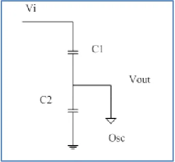
[image:24.595.252.423.329.487.2]A capacitive divider consists of two capacitors in series. It is commonly used to create a reference voltage, or to get a low voltage signal proportional to the voltage to be measured, and may also be used as a signal attenuator at low frequencies. For direct current and relatively low frequencies, a capacitive divider may be sufficiently accurate if made only of capacitors; where frequency response over a wide range is required, (such as in an oscilloscope probe), the voltage divider may have capacitive elements added to allow compensation for load capacitance. In electric power transmission, a capacitive voltage divider is used for measurement of high voltage. Figure 2.8 shows the capacitor divider connected in series.
Figure 2.8: Capacitor divider connected in series
Capacitive dividers do not pass DC input. Any leakage current in the capacitive elements requires use of the generalized expression with two impedances. By selection of parallel R and C elements in the proper proportions, the same division ratio can be maintained over a useful range of frequencies. This is the principle applied in compensated oscilloscope probes to increase measurement bandwidth. Formula for capacitive divider:
𝑉𝑜𝑢𝑡 = 𝐶2
13
2.6 Electrode Arrangement for Measurement of Breakdown Voltage
[image:25.595.136.532.443.589.2]There are various types of electrode arrangements and circuits for measurement of high voltages and currents such as sphere-sphere, sphere-plane, rod-rod, rod-plane and plane-plane. In this study two different electrodes (rod to plane and sphere to plane) have been used for the experimental study of the short air gap. The types of electrodes are vertically aligned as a figure 2.9. The lower plane electrode which is above the ground plane is grounded where as the top rod and sphere electrode is connected with HV connector. The used rod electrode has a diameter of 0.75 cm, sphere and plane electrode same diameter of 2.5cm. The electrode is made of aluminum material and air is acting as an insulating medium between sphere electrodes. The upper sphere electrode is connected in the high voltage terminal and the lower electrode is connected with the ground terminal. With the application of the high voltage between the sphere electrodes, a non-uniform electric field is generated as the surfaces of the sphere electrodes are not uniform. The HV electrode is energized from the 50 Hz transformer with a power rating of 5kVA with a transformation ratio of 220V/100kV [10].
Figure 2.9: Types of electrodes [10]
2.7 Finite Element Method Magnetic
FEMM is a suite of programs for solving low frequency electromagnetic problems on two-dimensional planar and axisymmetric domains. The program currently addresses linear/nonlinear magnetostatic problems, linear/nonlinear time harmonic
14
magnetic problems, linear electrostatic problems, and steady-state heat flow problems [15]. There are two type for solving using FEMM software such as electrostatic and magnetostatic.
Finite element method magnetic (FEMM) is widely used in the numerical solution of electric field problems. In contrast to other numerical methods, FEM is a very general method and therefore is a versatile tool for solving wide range of electric field problems. To start with, the whole domain is fictitiously divided into small areas/volumes called elements. The potential, which is unknown throughout the problem domain, is approximated in each of these elements in terms of the potential at their vertices called nodes. As a result of this the potential function will be unknown only at the nodes.
2.8 Previous Related Work
There have been several studies done before to develop the air breakdown characteristic rod plane and sphere plane. This project uses a lot of projects that were done in previous thesis, journal, and papers.
15
equipment. The above experiment is conducted at the normal temperature and pressure. The simulation of such air breakdown voltage has been carried out in the COMSOL environment.
Paraselli Bheema Sankar [5] has presented that “Measurement of Air Breakdown Voltage and Electric Field Using Standard Sphere Gap Method”. The thesis project is to simulate the air breakdown voltage experimentally in high voltage laboratory. The sphere gaps are filled up with insulating medium such as liquid insulation (transformer oil), solid insulation (polyester, paper) and gas insulation (SF6, N2, CO2, CCl2F2 etc.). Normally air medium is widely used as an insulating medium in different electrical power equipment‟s as its breakdown strength is 30 kV/cm. Therefore electrical breakdown characteristic of small air gap under the different applied voltage has its great significance for the design consideration of various air insulated HV equipment. In this work to simulate the air breakdown voltage experimentally in high voltage laboratory, standard diameter of 25 cm spheres are used for measurement of air breakdown voltages and electric field of the high voltage equipment‟s. The above experiment is conducted at the normal temperature and pressure. Finite element method is also used for finding the electric field between standard sphere electrodes. The relative air density factor and maximum electric field are measured in MATLAB environment for different temperature and pressure. The electric field distribution for sphere gap arrangements is also calculated with the help of COMSOL.
16
distributions when the breakdown voltage saturated within the investigated contact gaps 10 to 50mm. Within the contact gaps 10 to 50 mm, U50 of vacuum interrupter with contact radius of curvature 2 mm was higher than that of vacuum interrupter with contact radius of curvature 6 mm. And U50 of contact roughness 1.6 μm was close to that of contact roughness 3.2 μm. U50 of the contact diameter 60 mm was close to that of contact diameter 75 mm. And 50% breakdown voltage U50 depended on the contact gap, d (10-50 mm) for four interrupters, can be expressed by an equation U50=kd
α
, where α is a power exponent; k denotes a coefficient which can be determined by experiments. And under our experimental condition, power α lay in a range of 0.6-0.7 for the four vacuum interrupters. The breakdown phenomenon could be due to the micro-particles.
Subrata Karmakar [19] has presented that “An experimental study of air breakdown voltage and its effects on solid insulation”. The thesis project is to protect such equipment‟s different types of conducting electrodes having protective gap are used widely throughout the world. This project is a work from. The author describes the standard sphere electrodes are commonly used for this purpose among those all electrodes configuration. In the author study to simulate the air breakdown voltage experimentally in high voltage laboratory, standard diameter of 25 cm spheres are used for measurement of air breakdown voltages at NTP. In addition, the air breakdown voltage with insulation barrier and without insulation barrier is investigated inside the high voltage test laboratory. The effects of the breakdown voltage on paper insulation have been investigated in this work for quality assessment. The comparison of microstructure before and after the breakdown test reveals the information about the effects of electrical stress on the insulating paper.
17
that of SF6. At above pressures of 400 kPa and 15 mm electrode gap spacing, there exists a critical field where the breakdown voltage of CO2 has a maximum value.
2.8.1 Summary of previous related works
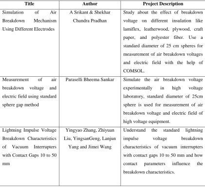
[image:29.595.109.531.380.767.2]In the process to completing this project, some thesis was used as the references. Table 2.2 shows the summary of previous related works. From the below summary of previous related work, this project is very useful to add some contribution air breakdown research. From the thesis, can be used as a reference and give some idea of this project. Many situation was tested the electrodes in the air breakdown. The voltage is affected by the gap length between the two electrodes and if the Emax is high, the electrode easier to breakdown.
Table 2.2: Summary of previous related works
Title Author Project Description
Simulation of Air Breakdown Mechanism Using Different Electrodes
A Srikant & Shekhar Chandra Pradhan
Study about the effect of breakdown voltage on different insulation like lamiflex, leatherwood, plywood, craft paper, and polyester fiber. Use a standard diameter of 25 cm spheres for measurement of air breakdown voltages and electric field with the help of COMSOL.
Measurement of air breakdown voltage and electric field using standard sphere gap method
Paraselli Bheema Sankar Simulate the air breakdown voltage experimentally in high voltage laboratory, standard diameter of 25cm sphere is used for measurement of air breakdown voltage and electric field of high voltage equipment.
Lightning Impulse Voltage Breakdown Characteristics of Vacuum Interrupters with Contact Gaps 10 to 50 mm
Yingyao Zhang, Zhiyuan Liu, YingsanGeng, Lanjun
Yang and Jimei Wang
18
An experimental study of air breakdown voltage and its effects on solid insulation
Subrata Karmakar Simulate the air breakdown voltage experimentally in high voltage laboratory, standard diameter of 25 cm spheres are used for measurement of air breakdown voltages at NTP.
Breakdown Characteristics of Gases in Non-Uniform Fields
Emel Onal Study of the breakdown voltage-pressure characteristics of SF6, CO2, N2
CHAPTER 3
LIGHTNING IMPULSE TEST PROCEDURE & SIMULATION MODEL
3.1 Introduction
This project deals to generate the air breakdown voltage by using lightning impulse voltage circuit by using manual guide TERCO in high voltage laboratory. Finite element method magnetic (FEMM) software is used to simulate the electric field (Emax) between difference electrodes. While, up and down method is used to get the 50% breakdown voltage (U50) during the experimentally.
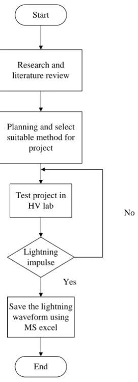
3.2 Method for Generation of Lightning Impulse
20
Start
Research and literature review
Planning and select suitable method for
project
Test project in HV lab
Lightning impulse
Save the lightning waveform using
MS excel
End
No
[image:32.595.263.399.67.443.2]Yes
Figure 3.1: Method to generate lightning impulse
3.3 Experimental Setup for Measurement of Lightning Impulse Voltage
21
Figure 3.2: Experimental setup lightning impulse voltage [9]
Figure 3.3: Block diagram for lightning impulse circuit
3.3.1 Equipment in the Generation of Impulse Voltages Circuit
3.3.1.1 HV 9103 Control Desk
[image:33.595.118.528.356.527.2]22
[image:34.595.120.536.124.346.2]house the measuring instruments (peak, impulse and DC voltmeters) and also the trigger device. The HV 9103 is fabricated of steel and stands on four wheels.
[image:34.595.207.435.450.611.2]Figure 3.4: HV 9103 Control desk [10]
Table 3.1: Description the button for control board
No Description the button
1 Control switch 2 Mains switch 3 ON – Primary 4 ON –Secondary 5 OFF – Secondary 6 OFF – Primary 7 Voltage regulation 8 Measuring sphere gap
3.3.1.2 HV 9105 Test Transformer
Figure 3.5 shows the test transformer with coupling winding for cascade connection to produce AC high voltage. The transformer consists of three windings with insulating shell and top and bottom corona free aluminum shielding electrodes.
1 1
5 4 3 2
8 1
7 1 6
23
Figure 3.5: HV 9105 Test transformer [10]
3.3.1.3HV 9111 Silicon Rectifier
[image:35.595.195.450.431.545.2]Figure 3.6 shows the silicon rectifier. The silicon rectifier is use in impulse voltage and DC voltage generation. The value of protective resistor is 100 k Ω.
Figure 3.6: HV 9111 Silicon rectifier [10]
3.3.1.4 HV 9112 Smoothing Capacitor
24
Figure 3.7: HV 9112Smoothing capacitor [10]
3.3.1.5 HV 9152 Impulse voltmeter (digital display)
[image:36.595.223.413.400.578.2]Figure 3.8 shows the impulse voltmeter (digital display). The function of impulse voltmeter is to measure the impulse voltage peak and can use for connection to the load capacitor.
Figure 3.8: HV 9152 Impulse voltmeter (digital display) [10]
3.3.1.6 HV 9130 Low Voltage Divider
REFERENCES
[1] Dr.S.L Uppal, “Electrical Power”, Indian Universities, Engineering Colleges ; Indian Institutes of Technology, State Boards and Institution of Engineers, pp. 1168 - 1198, 1988.
[2] Dr. Mohd Nor Ramdon bin Baharom, „HV Generation & Testing 1.0‟, High Voltage Engineering, MEK10303, February 2013.
[3] K. Schon, “High Impulse Voltage and Current Measurement Techniques”, Springer International Publishing Switzerland 2013.
[4] A Srikant & Shekhar Changra Pradhan, “Simulation Of Air Breakdown Mechanism Using Different Electrodes”, Department of Electrical Engineering National Institute of Technology, Rourkela Odisha 2011.
[5] Paraselli Bheema Sankar, “Measurement Of Air Breakdown Voltage And Electric Field Using Standard Sphere Gap Method”, Department of Electrical Engineering National Institute of Technology, Rourkela, June 2011.
[6] BSI Standard Publication, “High-voltage test techniques”, Part 1: General definitions and test requirements, BS EN 60060-1:2010.
[7] M.S. Naidu and V. Kamaraju, „High Voltage Engineering‟, published by Tata McGraw-Hill 3rd edition, 2004
[8] Univ.Prof. Dr. Frank Berger, 2004-2014 (online), available: https://www.tu- ilmenau.de/en/department-of-electrical-apparatus-andswitchgear/laboratories-and-equipments/high-voltage-laboratory/, (Accessed: 9 May 2014)
[9] TERCO “High Voltage Experiments”, manual guide at high voltage laboratory, 2014.
64
[11] IEC Publication 60052, “Voltage measurement by means of standard air gaps”, Geneva, 2002.
[12] A. S. Pillai and R. Hackam, “Electric field and potential distributions for unequal spheres using symmetric and asymmetric applied voltages”, IEEE Transactions on Electrical Insulation, Vol. EI-18, No.5, October 1983.
[13] Q. Liu, Z.D. Wang and F. Perrot, “Impulse Breakdown Voltages of Ester-based Transformer Oils Determined by Using Different Test Methods”, Annual Report Conference on Electrical Insulation and Dielectric Phenomena, 2009.
[14] Matthew N. 0. Sadiku “A Simple introduction finite element analysis of electromagnetic problems”, IEEE transactions on education, vol. 32, no. 2, may 1989.
[15] Yingyao Zhang, Zhiyuan Liu, Yingsan Geng, Lanjun Yang and Jimei Wang, “Lightning Impulse Voltage Breakdown Characteristics of Vacuum Interrupters with Contact Gaps 10 to 50 mm”, IEEE Transactions on Dielectrics and Electrical Insulation Vol. 18, No. 6; December 2011
[16] David Meeker “FEMM 4.2 Electrostatics Tutorial”, January 25, 2006
[17] O.W. Andersen “Finite element solution of complex potential electric fields” IEEE Transactions on Paver Apparatus and Systems, Vol. PAS-96, no. 4, July / August 1977.
[18] David Meeker “Finite Element Method Magnetics Version 4.2 User‟s Manual”, October 16, 2010
[19] Subrata Karmakar “An Experimental Study of Air Breakdown Voltage and its Effects on Solid Insulation”, J. Electrical Systems 8-2 (2012): 209-217 [20] Emel Onal “Breakdown Characteristics of Gases in Non-Uniform Fields”
journal of electrical & electronics engineering, 2004
[21] J. B. Nah. Kang, Y. D. Chung, M. C. Ahn, D. K. Bae and T. K. Ko, “Study on the breakdown voltage characterization of insulation gases for developing a high voltage superconducting apparatus”, IEEE Transactions on Applied Superconductivity, Vol.20, No.3, June 2010.
[22] Sayedsaad, September 2011 (online), available: http://www.sayedsaad.com /High_voltage/insulating gases_4.htm (Accessed: 21 March 2014)
65
[24] IEC 60060-2:1973, High-voltage test techniques - Part 2: Test procedures. [25] Athanasios Maglaras and Frangiskos V. Topalis, “Influence of Ground and
Corona Currents on Dielectric Behavior of Small Air Gaps”, IEEE Transactions on Dielectrics and Electrical Insulation, Vol. 16, No. 1, February 2009.
[26] P. Ortega, R. T. Waters, A. Haddad, R. Hameed and A. J. Davies “Impulse Breakdown Voltages of Air Gaps: A New Approach to Atmospheric Correction Factors Applicable to International Standards”, IEEE Transactions on Dielectrics and Electrical Insulation, Vol. 14, No. 6, December 2007. [27] N. K. Kishore, G. S. Punekar, H. S. Y. Shastry, “Spark Over in Sphere Gaps
With Alternating voltages and Perturbed Electric Fields”, annual report conference on „Electrical Insulation and Dielectric Phenomena‟, 2009.
[28] R. Bartnikas, “Positive Streamer Propagation and Breakdown in Air: The Influence Of Humidity”, IEEE Transactions on Electrical Insulation, Vol. 15, No. 2, pp. 416-425, 2008.
![Figure 2.1: Standard lightning impulse voltage waveform [3].](https://thumb-us.123doks.com/thumbv2/123dok_us/8769798.898322/18.595.123.521.72.241/figure-standard-lightning-impulse-voltage-waveform.webp)
![Figure 2.2: Arrangement for Townsend‟s mechanism [7]](https://thumb-us.123doks.com/thumbv2/123dok_us/8769798.898322/19.595.176.462.370.535/figure-arrangement-for-townsend-s-mechanism.webp)
![Figure 2.3: Townsend‟s mechanism process [2]](https://thumb-us.123doks.com/thumbv2/123dok_us/8769798.898322/20.595.131.512.277.489/figure-townsend-s-mechanism-process.webp)
![Figure 2.4: Streamer mechanism [7]](https://thumb-us.123doks.com/thumbv2/123dok_us/8769798.898322/21.595.219.418.545.724/figure-streamer-mechanism.webp)
![Figure 2.5: Formation of secondary avalanches due to photo-ionization [7]](https://thumb-us.123doks.com/thumbv2/123dok_us/8769798.898322/22.595.179.464.588.733/figure-formation-secondary-avalanches-photo-ionization.webp)
![Figure 2.7: Flashover [8]](https://thumb-us.123doks.com/thumbv2/123dok_us/8769798.898322/23.595.225.454.257.312/figure-flashover.webp)
![Figure 2.9: Types of electrodes [10]](https://thumb-us.123doks.com/thumbv2/123dok_us/8769798.898322/25.595.136.532.443.589/figure-types-of-electrodes.webp)