FLOW VISUALIZATION OF BUBBLE STRUCTURE IN BUBBLE
COLUMN REACTOR FOR FLUID MIXING
Bukhari Manshoor
1, 4, Amir Khalid
2, 4, Nor Afizah Ibrahim
2, 4, Izzuddin Zaman
3, 4 1FAST Research Group, 2 ARG Research Group, 3 Structural Integrity and Monitoring Research Group,
4 Faculty of Mechanical and Manufacturing Engineering, Universiti Tun Hussein Onn Malaysia, 86400
Batu Pahat, Johor, Malaysia E-Mail: [email protected]
ABSTRACT
Bubble columns reactor is widely used as gas–liquid mixing and as reactors in many industries such as in chemical, petrochemical and biochemical. High interfacial area between the gas and liquid phase will enhanced an effective mixing, leading to improved heat and mass transfer characteristics under bubble columns become an attractive choice as reactors for the described processes. In this research, experimental work by using cylindrical acrylic bubble column with internal diameter of 0.15m and height of 1m was done. The bubble column is equipped by four nozzles with orifice diameter of 5 mm function as gas distributor attach at the bottom of the column. For this study, gas phase and liquid phase used are air and water respectively. The investigated variable parameter was mechanism of bubble formation, regime analysis and the relationship between superficial gas holdup and gas holdup. The techniques used in collecting data were visual observation, measurement technique and photographic method. The result showed that there were five stage of bubble formation based on experiment conducted. For gas holdup and superficial gas velocity relationship, it was discovered that the gas holdup increased with the increasing of superficial gas velocity. The relationship was proof to be in good agreement with published data proposed by previous researcher.
.
Keywords: Bubble column, gas holdup, bubble formation, visual observation
INTRODUCTION
Bubble column reactors is one of the multiphase reactors that intensively used in chemical, biochemical and metallurgical industries (Degaleesan et al., 2001). In order to have a better understanding on hydrodynamic properties, there are a few important parameters have been reviewing by research group which are bubble characteristics (Essadki et al., 1997), liquid-phase properties, gas distributor, gas holdup studies and flow regime investigations (Ruzicka et al., 2001). In bioprocess application, bubble column acts as a bioreactor in producing industrial valuable products such as enzymes and antibiotics. Recently, the study was more focused on the hydrodynamics properties of the bubble column (Prakash et al., 2001). In order to enhance the performance of the column, it is essential to understand the hydrodynamics properties. The hydrodynamics properties can be used in finding an alternative method of fluid mixing by focusing on bubble flow pattern inside the bubble column. This was proofed by Vial et al. which emphasize that the hydrodynamic and phase mixing depend strongly on the prevailing flow pattern (Vial et al., 2000).
The research is conducted to investigate the parameter that influence the hydrodynamic properties of bubble column in view of focusing on mechanism of bubble formation, relationship between gas holdup and superficial gas velocity and the regime analysis. The data
obtained from the experiment conducted under laboratory condition are important for future reference which can lead a better understanding in hydrodynamic properties and enhancing the performance and increase the efficiency of the bubble column reactor. The data obtained experimentally also being compared with data collected from previous research for reference purposes
.
EXPERIMENTAL SET UP
The experiment was carried out in a bubble column reactor with a diameter, d = 0.15m and height, H = 1m. The column was equipped with four nozzles with orifice diameter of 5mm function as gas distributor, as shown in Figure 1. The top part of the column was open to atmosphere. The column also equipped with control valve and mass flow measuring meter for gas flow control and measurement. The experimental set up was illustrated in Figure 2.
(a) (b)
[image:2.595.307.550.211.453.2]Figure 1: Four nozzles as a gas distributor attached at the bottom of the column
Figure 2: Experimental set up
All the experiment was conducted in ambient temperature and pressure condition. The working fluid used in experiment was water and the gas phase was atmospheric air. The experiment was performing at the superficial gas velocity of 0.007cm/s to 0.061cm/s. The experiment were initiated by starting the gas supply and filled up the column with appropriate amount of water up to 90cm above the nozzles. The digital camera was placed in standby position close to test section to observe the image of bubble flow pattern. The recorded image also used to obtain the event of bubble coalescence/breakage mechanism during bubble formation. For second part of the experiment, the average gas holdup is estimated by the bed expansion. The liquid level is measured on three different points prior to gas inflow and after gas is injected. The differences of liquid height were measured by the scale attached to the column at three different points as in Figure 3, and average reading of three levels was measured. The gas holdup values were calculated by the following equation.
(1)
where,
Hi = initial liquid height (without gas)
Hf = final liquid height (with gas)
(a) (b)
[image:2.595.68.280.276.487.2](c)
Figure-3. Bed expansion method for gas measurement (a) before gas injection (b) after gas injection and (c) the
difference of liquid height
RESULTS AND DISCUSSION
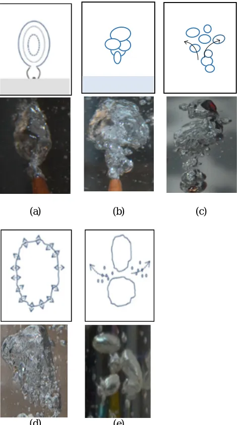
There are two interesting parts that were come out from the experimental work which are the formation of bubble that occurred in the column and also the gas hold up. Figure 4 shows the five stage of bubble formation discovered from the experiment. The first stage of bubble forming observed was channeling that take place in orifice. It was noticed that the first bubble start to develop in form of bubble neck. The next stage is bubble coalescence. This stage occur when the bubble form at the orifice start to elongate due to wake of preceding bubble effect. After the elongation process, detached bubbles were developed and collide with preceding bubbles resulting of bubble separation. This formation stage was labeled as segregation. After segregation, the large bubbles were generated due to large amount of air in bubble and long detachment period.
The second part that interesting in the study of flow in bubble column is a gas holds up. Gas hold up is a dimensionless quantity represents the percentage of total gas-liquid system occupied by the gas. Based on previous research done before, many researchers had stated that the gas holdup strongly depend on superficial gas velocity. In order to determine the value of the gas holdup, an
f f
i f
g H
H H
H
H
. exp
experiment had been conducted using varying range of superficial gas velocity. The values of gas hold up collected from the experiment were compared with correlation of gas holdup prediction in bubble column from previous research. The gas holdup obtained from experiment was determined by the visual observation of change in liquid height when the gas introduced in the bubble column.
(a) (b) (c)
[image:3.595.312.555.188.331.2](d) (e)
Figure 4: The schematic diagram (above) and images (below) of bubble formation mechanism
Figure 5 shows the relationship between the gas holdup and the superficial gas holdup. It is clearly observe that the percentage of the gas holdup increase simultaneously with the increase of the superficial gas velocity. Based on the graph, the percentage of the gas holdup started from 2.2 % with superficial gas velocity of 0.007cm/s. The gas hold up continues to rise to 3.6 % when the superficial gas velocity is 0.009cm/s. At 0.0012cm/s, the value of the gas holdup increase
moderately up to 4.3%. When the gas velocity changes to 0.027cm/s, the gas holdup also increase with 5.9%.At 0.042 cm/s, the percentage of the gas holdup changes to 6.8%.The percentage of the gas holdup reach the peak at the gas velocity of 0.056cm/s and 0.061 cm/s which 7.6% and 8.6% respectively.
Figure 5. Graph of gas holdup versus superficial gas velocity
Gas hold up correlation
[image:3.595.52.287.209.631.2]The gas hold up values was measure by using correlation proposed by previous researchers. Figure 6 shows the relationship between gas hold up for experiment and predicted gas holdup proposed by Joshi & Sharma (1979) and Kawase & Moo Young (1989a), (1989b). From the figure, it shows that from 0.009cm/s to 0.012 cm/s, the predicted gas holdup propose by Joshi and Sharma have closer percentage with experimental gas holdup where the experimental gas holdup have percentage of 3.6% and 4.3% in increasing air velocity While for Joshi and Sharma correlation, the percentage of the gas holdup is 2.8% and 3.7 % with increased of superficial gas velocity. In contrast with Kawase and Moo Young correlation which the predicted gas holdup have higher percentage 6.7% and 7.43% with increased of superficial gas velocity. At the maximum speed of the air which is 0.061cm/s, the gas holdup percentage obtained from the experiment is 8.6%.
Figure 1: Comparison between calculated gas holdup (experimental) and gas hold up (theory)
0 2.2
3.64.3
5.9 6.8
7.6 8.6
0 2 4 6 8 10
0 0.02 0.04 0.06 0.08
G
as
H
o
ld
u
p
(
%
)
[image:3.595.310.537.610.748.2]The gas holdup correlation predicts by Joshi and Sharma is 5.9% higher than experimental data which is 14.5%. For Kawase and Moo Young correlation, the predicted gas holdup is 4.2 % higher than the experimental data which have the percentage of 12.8%.
Drift flux slope changes
The change of slope from the relationship between the drift flux and the gas holdup were able to determine the types of flow regime developed. The value of the drift flux can be obtained from the following expression.
(2)
where,
J = the drift flux (cm/s)
= Superficial gas velocity (cm/s) = The Gas Holdup
[image:4.595.309.547.151.455.2]Figure 6 shows the plotted of drift flux against gas hold up. From the figure, the transition regime were develop when the range of the drift flux is from 0.0068 cm/s until 0.0115cm/s while the heterogeneous regime were encounter from 0.0254cm/s to 0.0558cm/s. Referred from previous research, the transition regime were develop where the rate of the gas holdup increase is lower compared to the heterogeneous regime. Heterogeneous regime commonly has intense interaction between bubbles which leads to coalescence event. In this type of regime, the bubbles usually have a large size due to coalescence between small and large bubbles. For the homogeneous regime which is one of the main flow regime exist in industrial, the regime commonly develop at low superficial velocity. The bubble is uniform and in small size.
Figure 7: Graph of drift flux against gas hold up
Observation of regime analysis
Visual observation used to identify the types of flow regime is possible by using transparent tubes. Visual observation is reliable but at a high velocity, it is difficult to see the flow especially in small column diameter. Only the flow near the column wall can be clearly seen. However, photographs with a high speed flash with proper lighting can help to overcome the high fluid velocities
problem. For this study, an experiment has been conducted to identify the flow regime and able to categorize the flow pattern into the regime analysis exist in industrial area.
Top region of the bubble column
Middle region of the bubble column
Bottom region of the bubble column
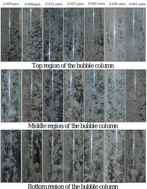
Figure 8: Image of flow regime obtained with superficial gas velocities range from 0.007cm,/s to 0.061cm/s with
initial liquid height of = 90cm
By referring to the Figure 8 below, there are two types of regime analysis discovered from the experiment which is transition regime and heterogeneous regime. The transition regime can be observed from the air velocity of 0.007cm/s and 0.009cm/s. From the figure, the heterogeneous regime can be observed from superficial gas velocity of 0.012cm/s to 0.061cm/s. The heterogeneous regime can be identifying based on the intense of bubble coalescence and break-up. Large and small bubble simultaneously appear in this flow regime leads to large bubble distribution. This flow regime also develops vigorous circulation of the bubble. Heterogeneous flow regime commonly occurs at high gas superficial velocity compared to transition regime.
For transition regime, as can be seen in the bottom part of the image where the air velocity is 0.007cm/s, large bubble were generate from the orifice. Due to high air velocity supplied from the air pump, the bubble start to elongate with preceding bubble and the large bubble were generated due to coalescence event. While for the top part, it can be observed that the cluster were develop approaching towards the end path of the water level. The bubble inside the column starts to interact and collide with each other. The air from the bubble starts to escape toward
g
gs U
[image:4.595.52.267.521.663.2]the open end of the bubble column. The bubble collision phenomenon enhances the bubble cluster to form. This phenomenon was continuously observed until the superficial gas velocity reach 0.009cm/s.
For heterogeneous regime, as observed in bottom part of column which have the superficial gas velocity of 0.042cm/s, the large bubble interact with each other directly or indirectly and collide with the column wall. It also can be observed that most of the large bubble fulfils the column space. For the middle part of the column, the number bubble density have a further increase and in turbulent form. The large bubble frequently forms clustering of bubbles. The phenomenon continues towards the top part of the column.
The heterogeneous regime can be identifying based on the intense of bubble coalescence and break-up. Large and small bubble simultaneously appear in this flow regime leads to large bubble distribution. This flow regime also develops vigorous circulation of the bubble. Heterogeneous flow regime commonly occurs at high gas superficial velocity compared to transition regime.
CONCLUSIONS
There are three main variable parameter investigated to fulfill the objective of the experiment. The parameter are mechanism of bubble formation, gas holdup and regime analysis. The first parameter investigate is the mechanism of bubble formation. It can be summarize that there are five stages in bubble formation which are the channeling on the orifice, bubble coalescence and segregation, generation of large bubble with vibrating surface and generating of small bubbles. For gas holdup, the results showed that the increase of the superficial gas velocity will increase the gas holdup. The experiment data also being compare with correlation propose by previous research.
Although the experimental data does not have the exact result with propose correlation, the result obtain is quite close with theoretical data. The third parameter investigate is the flow visualization of bubble column reactor. There are two out of three types of regime analysis present in industrial area were discovered in experiment The main regime analysis are homogeneous regime, transition regime and heterogeneous regime. It is difficult to encounter the homogeneous regime under laboratory condition. Due to that, only transition and heterogeneous regime were discovered in experiment. In summarizing all the three variable parameter, it can be concluded that the prevailing flow regime depend simultaneously on parameter such as gas holdup, superficial gas velocity and liquid properties.
ANCKNOWLEDGEMENT
Partial support was provided by MOHE (Ministry of Higher Education, MALAYSIA) and Universiti Tun Hussein Onn Malaysia (UTHM) under the Fundamental Research Grants Scheme (ERGS), vote E033.
REFERENCES
Degaleesan, S., Dudukovic, M. and Pan, Y. (2001). Experimental study of gas-induced liquidflow structures in bubble columns. AIChE Journal, 47, 1913–1931.
Essadki, H., Nikov, I. and Delmas, H. (1997). Electrochemical probe for bubble size prediction in a bubble column. Experimental Thermal and Fluid Science.
Joshi, J.B., and Sharma, M.M., (1979). A circulation cell model for bubble columns. Transactions of the Institution of Chemical Engineers 57, 244–251
Kawase, Y., Moo-Young, M., (1989a). Turbulence intensity in bubble columns. Chemical Engineering Journal 40, 55–58.
Kawase, Y., Moo-Young, M., (1989b). Mixing time in bioreactors. Journal of Chemical Technology and Biotechnology 44, 63–75.
Prakash, A., Margaritis, A., Li, H., & Bergougnou, M. A. (2001). Hydrodynamics and local heat transfer measurements in a bubble column with suspension of yeast. Biochemical Engineering Journal, 9, 155–163.
Vial, C., Camarasa, E., Poncin, S., Wild, G., Midoux, N., & Bouillard, J. (2000). Study of hydrodynamic behaviour in bubble columns and external loop airlift reactors through analysis of pressure fluctuations. Chemical Engineering Science (Vol. 55, pp. 2957–2973).