to Part L and Robust Details on Part C -Interim report number 7: Final report on project fieldwork. Project Report. A Report to the ODPM Building Regulations Division under the Building Operational Performance Framework.
Link to Leeds Beckett Repository record:
http://eprints.leedsbeckett.ac.uk/823/
Document Version: Monograph
c
Queen’s Printer and Controller of Her Majesty’s Stationery Office, 2005
You are encouraged to use and re-use the Information that is available under this licence freely and flexibly, with only a few conditions.
The aim of the Leeds Beckett Repository is to provide open access to our research, as required by funder policies and permitted by publishers and copyright law.
The Leeds Beckett repository holds a wide range of publications, each of which has been checked for copyright and the relevant embargo period has been applied by the Research Services team.
We operate on a standard take-down policy. If you are the author or publisher of an output and you would like it removed from the repository, please contact us and we will investigate on a case-by-case basis.
Robust Details on Part C
Project Reference Number: CI 71/6/1 BD2414
Interim report number 7: Final report on project
fieldwork
Malcolm Bell, Melanie Smith & Dominic Miles-Shenton
Interim report to ODPM Building Regulations Division under the
Building Operational Performance Framework
Project Title:
CONDENSATION RISK – IMPACT OF IMPROVEMENTS TO PART
L AND ROBUST DETAILS ON PART C
Reference Number: CI 71/6/1 BD2414
Milestone number C1:M7
Interim report number 7: Final report on project fieldwork
Report prepared by Proposal checked by Proposal approved by
Malcolm Bell, Melanie Smith and Dominic Miles-Shenton (Leeds Met)
Name: Tadj Oreszczyn (UCL) Name
Organisation: Centre for the Built Environment, Leeds Metropolitan University, Brunswick Terrace, Leeds LS2 8BU
Organisation: Bartlett School of Gradate Studies, University College London, Gower Street, London WC1E 6BT
Faber Maunsell
Project Manager: Malcolm Bell Project Mentor: Tadj Oreszczyn Lead Contractor
Signature Signature Signature
TABLE OF CONTENTS
Executive summary ...5
Acknowledgements...8
Reproduction of Robust Details...8
CHAPTER 1 - Introduction ...9
Report status ... 10
CHAPTER 2 – Fieldwork Methodology ... 11
Workshop phase... 11
Site selection phase... 11
Design review phase ... 14
Site assessment phase ... 15
Data storage ... 16
Developer feedback... 16
CHAPTER 3 - Results of Design and Construction Assessments ... 17
Design information... 17
Design and construction ... 20
Ground floor – wall junctions ... 20
Intermediate floor – wall junctions ... 28
Balconies ... 33
Windows and door openings ... 35
Room-in-the-roof details ... 43
Insulating around cavity trays ... 50
Timber panel construction ... 55
Airtightness and vapour control ... 57
CHAPTER 4 - Discussion, conclusions & selection of details for the modelling phase ... 67
Prevalence of problems... 67
Limitations of the field study ... 68
Summary of key findings ... 69
Implications for Robust Detail guidance ... 72
Selection of details for condensation modelling ... 73
References ... 75
Appendix 1... 77
Executive summary
This report sets out, in draft1, the results of the fieldwork phase of research into the impacts of the 2002 revisions to Part L of the building regulations (Approved Document L1 - DTLR, 2001), and the adoption of Robust Details (RDs - DEFRA 2001) on the extent of condensation risk in the construction of dwellings (Oreszczyn and Bell, 2003). The objective of the fieldwork was to explore the practical application of the revised Part L and its associated robust details by housing developers. This was done through a qualitative evaluation of the design and construction of 16 housing schemes designed in accordance with the revised part L and making use of robust details2. The results of the analysis are to be used to enable condensation modelling that takes into account not only the guidance of robust details but also the way in which construction details were actually designed and, perhaps more importantly, constructed. To this end the report identifies 7 areas of construction detailing (yielding some 15 separate detail models) that are to be included in the condensation modelling phase of the project.
The analysis was undertaken in two phases, a desk study of the design material provided by developers and an assessment of the way details were constructed, including observations on the way design information was communicated to the construction team and used on site. A draft version of the report was sent, for comment, to the developers involved and their comments are included in the discussion in Chapter 4. In seeking to understand and place in perspective the results of the fieldwork it is important to understand the general issues raised by the specific observations and to avoid classifying the problems identified as “errors, defects or mistakes”. Like all general problems of quality management, the underlying issues are ones of system, not of individual or developer culpability. The qualitative analysis of data from the 16 sites investigated has led to the following broad findings relating to design and construction
a) The level of knowledge and understanding relating to robust details was generally low. This is particularly true at the construction end of the process with the very existence of robust details for part L (as opposed to part E – sound) not widely recognised by many people on the sites studied. Knowledge, within the design community, of the existence of Part L RDs was more widespread but many drawings lacked sufficient detail to be certain of the extent to which designers understood the principles involved or how to apply the guidance effectively.
b) The communication of detailed design requirements from designer to constructor (particularly the operative constructing a particular detail) was not always very clear. On some sites this stemmed from a lack of detailed design material. In a number of cases operatives worked from large scale (1:50 or 1:100) general arrangement drawings rather than large scale details and, to some extent, details seemed to be worked out on site. In other cases large scale details were available but not always as accessible as they might be.
c) The placement of insulation, particularly where rigid boards were used, often allowed the circulation of air around the insulation, resulting in a reduction in thermal
performance.
d) Gaps in the insulation layer were common, particularly around difficult details, leading to reduced insulation at critical points and increasing the risk of surface and interstitial condensation. In general, wherever small areas required insulation, or awkward cuts were required, insulation was omitted or substantial gaps left.
1 This version of the fieldwork report is presented, for comment, to the developers who took part in the investigation and to
those who took part in the initial project workshop.
2 Robust details (DEFRA 2001) are specified in Approved Document L1 (DTLR 2001) as providing a compliance route for
e) The use of proprietary cavity closures in masonry construction was common but many were uninsulated. Given the frequency of this observation, it is likely that they were used in the erroneous belief that they eliminated the thermal bridge and satisfied the guidance in the RD document.
f) The goal of creating a continuous air and/or vapour control layer was not reliably achieved on almost all of the sites visited. In masonry construction the use of plasterboard on dabs was universal but in one case only was it possible to see a reasonable attempt to create a continuous ribbon of adhesive around boards and at penetrations. On timber frame sites, although reasonable attempts were made to install an air/vapour control layer, some parts of the structure, particularly at isolated multiple stud sections, had no barrier at all. Ensuring continuity of barriers at junctions was a general problem throughout.
g) Damage to or ill-fitting air/vapour control layers were often observed with little attempt at repair or sealing. The areas behind bathroom and kitchen fittings or inside services duct spaces were the most vulnerable. This is of particular concern given the intermittently high vapour pressures in these locations. Damage resulting from services penetrations was a particular problem despite attempts at sealing. The approach taken to the design of service penetrations (a “puncture and seal” approach) does not appear to result in robust design or construction. Very often sealing is carried out where services enter secondary spaces, such as floor voids but not where they penetrate the air/vapour barrier itself.
h) Detailing around major structural elements did not appear to allow for the thermal bridging effects. This was particularly true of the detailing around multiple timber studs and structural steel sections.
i) Some thermal bridging resulted from the misalignment of components such as windows and doors with respect to the placement of insulation. In a number of cases the
construction of bay windows involved fixing the frame to the outer leaf of brick work, resulting in a significant thermal bridge.
Although the research did not set out to provide a statistical picture of the house building industry’s response to Part L 2002 and robust details, an assessment was made of the
prevalence of the problem areas that were observed. Some 20 key problem areas were identified with 16 of these being observed on at least half the potential number of sites3.
Throughout the field work it was clear that much more needs to be done to disseminate the requirements of Robust Details and that the form and content of the document should be revised. A table of detailed improvements is provided in appendix 1. As well as extending the coverage of the details themselves, it was concluded that much more emphasis is needed on the principles that lie behind the details, together with expected performance characteristics. Many of the problems identified resulted from operations that were made more difficult by obstructions. In order to reduce this problem and make details more “buildable” it is suggested that the RD guidance include an indication of the order in which operations should to be carried out.
Appendix 2 contains a list of the seven areas of construction that are to be subjected to condensation modelling. The set of details chosen was designed to reflect the prevalence of problems, the generality of problems across construction types, the important junctions involved and to ensure an assessment that involved all forms of construction included in the study.
3 In this context, potential, is defined as the number of sites on which a particular problem could have been observed,
In reading the results of the fieldwork it is important to realise that it does not claim to be representative of UK dwelling construction post the 2002 edition of Part L4. However, its usefulness lies in the considerable insight it provides into some of the design and construction issues that need to be addressed by all those involved in the house building industry if the quality and performance of new dwellings is to be improved.
Acknowledgements
We would like to acknowledge the help and support of those developers who took part in the study. We are very grateful for the enthusiasm with which they took part and the invaluable help received by designers and site staff who were very generous with their time. We are grateful also for the anonymous use of illustrative design material, the copyright in which lies with the
designers. The views expressed in this report are those of the authors and are not intended to represent those of the Office of the Deputy Prime Minister. Responsibility for any errors or omissions lies, as always, with the authors.
Reproduction of Robust Details
The illustrations of robust details used in this report are taken from DEFRA (2001) Limiting Thermal Bridging and Air Leakage. Robust Details for Dwellings and Similar Buildings. Department for the Environment, Food and Rural Affairs. London, TSO. They are reproduced
CHAPTER 1 - Introduction
1. This report constitutes milestone M6, “Draft fieldwork report”, of the ODPM Project;
Condensation Risk – Impact of Improvements to Part L and Robust Details on Part C
(Oreszczyn and Bell, 2003); project reference CI 71/6/1 (BD2414).
2. The 2002 edition of Part L of the Building Regulations and its Approved Document L1 for dwellings introduced lower U values and strengthened the requirements for air-tightness. This project was established in order to address the implications of these changes for condensation risk (dealt with under Part C of the Regulations ). As part of the review of Part L (DTLR, 2001) DEFRA and DTLR published a set of construction details (Robust Details, DEFRA, 2001) that were to be used in conjunction with the Approved Documents L1 and L2 (ADL1, ADL2) to assist the construction industry in reducing thermal bridging and improving the airtightness of the thermal envelope. The Robust Details document contains some 130 details, covering six construction types. These details form the cornerstone of ADL1 in that they provide the principal compliance route for dwellings with respect to thermal bridging and airtightness. One of the key objectives of the research project in general and the fieldwork element in particular was to establish how Robust Details were being applied by designers and how they were being implemented in construction on site. The results of this analysis are to be used to define a representative set of details that will be subjected to detailed condensation analysis using both simple (steady state) and the more complex dynamic simulation methods. This report collates the findings of the field work and identifies the areas of detail design and construction that are to be subject to condensation analysis.
3. The project began with an industry workshop (held in December 2003) the aim of which was to identify those construction details which were perceived by the industry as being the most problematic in terms of incorporating them into the design of residential properties, construct on site or to create problems once built. The information gained from this workshop was used in the formulation of site selection and data collection procedures. Data relating to the design and construction of 2002 compliant developments where Robust Details were used was collected from 16 development sites, and was analysed so as to build up a picture of the implementation of the 2002 regulations and the use of Robust Details. Following the analysis, seven areas of construction detail and associated Robust Details were selected for detailed modelling. The field work was carried out between the beginning of May and the end of September 2004 by a team from Leeds Metropolitan University and the modelling work is being conducted by a team at University College London.
4. The work covered in this report supports research task 2 as set out in the project
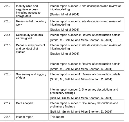
proposal (Oreszczyn and Bell, 2003). Details of the sub-tasks and related interim reports are set out in table 1.1:
Task Task title Contained in Interim Report
2.1 Workshops Interim report number 1: Initial workshop & site selection criteria
(Smith, M. and Bell, M. 2004) 2.2 Site survey As below
2.2.1 Establish criteria for site
2.2.2 Identify sites and negotiate access including access to design data
Interim report number 2: site descriptions and review of initial modelling
(Davies, M. et al 2004)
2.2.3 Review initial modelling
work Interim report number 2: site descriptions and review of initial modelling (Davies, M. et al 2004)
2.2.4 Desk study of details –
as designed Interim report number 4: Review of construction details (Smith, M., Bell, M. and Miles-Shenton, D. 2004)
2.2.5 Define survey protocol and conduct pilot
studies
Interim report number 2: site descriptions and review of initial modelling
(Davies, M. et al 2004)
Interim report number 4: Review of construction details (Smith, M., Bell, M. and Miles-Shenton, D. 2004) 2.2.6 Site survey and logging
of data Interim report number 4: Review of construction details (Smith, M., Bell, M. and Miles-Shenton, D. 2004)
Interim report number 5: Site survey descriptions and preliminary findings
(Bell, M., Smith, M. and Miles-Shenton, D. 2004) 2.2.7 Data analysis Interim report number 5: Site survey descriptions and
preliminary findings
[image:11.612.85.530.64.483.2](Bell, M., Smith, M. and Miles-Shenton, D. 2004) 2.2.8 Interim report This report
Table 1.1 Details of tasks and related reports.
Report status
CHAPTER 2 – Fieldwork Methodology
6. The objectives of this part of the project were to investigate actual construction details, as designed and constructed and to estimate the possible influence of such things as buildability and workmanship on the performance of Robust Details (RDs). To respond to these objectives, the fieldwork element has focussed on emerging practices in the use of domestic Robust Details following the 2002 revision of Part L of the Building Regulations for England and Wales (DTLR, 2001). Both design and the construction practices in the application of Robust Details have been established within the confines of the project, with particular reference to the impact of practice on condensation risk.
7. The fieldwork element was conducted in four phases
• An industry workshop to review Robust Details and to establish key issues, • Site selection
• Analysis and review of construction design drawings • Surveys of construction on the selected sites
Workshop phase
8. A workshop was held in December 2003 at Leeds Metropolitan University. Workshop participants included private sector housing developers, social housing developers, representatives from the timber frame and steel frame industries, building control officers and approved inspectors, and representatives from industry material suppliers and trade associations. The results of the workshop are reported in Smith and Bell (2004).
9. During the workshop sessions, the experience and opinions of the participants regarding design and construction issues were explored. The participants were asked to discuss a number of questions relating to their practical experience of the use of Robust Details on site and changes in design and site practice due to the improved measures contained in Part L of the Building Regulations. In particular, any details that were causing difficulties or concerns were to be identified. Following this, a number of vulnerable Robust Details were selected for preliminary investigation by the research team.
10. During the analysis phase of the fieldwork, the findings of the workshop were revisited and reviewed.
Site selection phase
11. Over 20 housing developments were identified yielding 16 sites suitable for data collection. The selection was based on the need for developments to be designed to 2002 Part L requirements and the desire to cover representative areas of England, the four main construction types, and a mixture of private and social development.
12. Sites were selected according to the following general criteria agreed at the workshop: a. the sites must to be designed and constructed under approvals issued in accordance
with the 2002 edition of Building Regulation Part L1 and to adopt Robust Details as the compliance route for thermal bridging and airtightness (paragraphs 1.31 and 1.34 ADL1),
b. the developments to be designed and under construction between February and September 2004,
d. four geographical areas of England were to be represented (North East, North West, South East and South West),
e. both large and smaller developers were to be included, and f. sites were to be a mix of social and private developments.
13. The key characteristics of the sites selected, together with an outline of the data available and the number of site visits undertaken are set out in table 2.1. A key to the
abbreviations used in the table is provided in box 1 below.
Key to table 2.1
P/F = Masonry construction with the cavity partial-filled with insulation
F/F = Masonry construction with the cavity fully-filled with insulation
T/F = Timber framed construction
S/F = Steel framed construction
Fdn = Foundation
Bkwk = brickwork. In this case (only) this may include stonework and reconstituted stonework
1st lift and 2nd lift refer to heights of scaffolding. Generally 1st lift is the external walls to first floor level, and 2nd lift at first floor level and so on.
1st fix is the stage of construction where the framework for floors, walls and/or roofs are being placed.
2nd fix is the stage of construction where the internal claddings to floors, walls, ceilings and/or roofs are being placed e.g. plasterboard, floorboarding etc.
GA = general arrangement drawings, showing show where properties are to be placed on the site, and general layout plans for the properties, usually at 1:100 or 1:50 scale, sometimes with a section through the dwelling. These do not show in sufficient detail how the construction will actually be put together.
Site reference Type of Development
Region Private
/Social
Type Construction stage
seen on site
No. of visits to site
Detail of drawings received
GA = general arrangement C1 6 terraced houses NE Private P/F 1. Fdn bkwk
2. 2nd lift 2 site visits GA drawings only, no detail except 1:20 partial section C2 3 storey flats NE Private P/F 2nd lift 1 site visit GA drawings plus details
C3 3 & 4 storey flats, 3 storey terraces
NW Private T/F Fdns to 2nd fix 1 site visit GA drawings plus details
C4 5 storey flats, 3 storey houses, duplex flats
NW Private T/F Slabs to completion 1 site visit GA drawings plus details
C5 85 dwellings houses & flats
NE Social P/F Slabs to 1st fix 1 site visit Site plan & details only, no GA drawings
C6 2 & 3 storey flats and houses
SW Social P/F Slabs to 1st fix 1site visit Site plan & details only, no GA drawings
C7 3 detached houses NE Private P/F 1. fdn & slabs
2. no change; 3. 2nd lift 3 site visits GA drawings only, no details C8 95 terraced,
semi-detached and flats
SE Social T/F Fdns to 2nd fix 1 site visit GA drawings plus details
C9 77 dwellings, flats, semis, terraced
SE Social T/F Fdns to 1st fix 1 site visit GA drawings plus details
C10 30 semis and terraced houses
NE Private F/F Fdns to 2nd fix 1 site visit GA drawings only, no details
C11 48 flats in four storeys NE Private T/F 2nd lift to 2nd fix 1 site visit GA drawings only, no details C12 20 detached houses NW Private P/F Fnd bkwk, 2nd fix &
completion 1 site visit No drawings received C13 104 semis & detached
houses
NW Private S/F Slabs to completion 2 site visits GA drawings and developer’s details
C14 130 terraced, semi & detached houses
NW Private S/F & P/F Slabs to 1st fix 1 site visit No drawings received
C16 46 plots SW Private F/F Slabs to completion 1 site visit No drawings received C20 3 blocks of four storey
flats
NE Social P/F 2nd lift 1 site visit GA drawings and details
Summary 16 sites NW 5 NE7 SW 2 SE 2 Social 5 Private 11 FF 2 PF 8 TF 5 SF 2
Fdn bkwk/slab 16 Shell 16
1st fix 12
2nd fix/completion 8
Site visits 20 No of sites 16
[image:14.612.32.761.70.539.2]Drawings received from designers 13 Drawings not received from designers 3
Design review phase
14. The drawings produced for a building contract will usually include plans, sections, elevations and detail drawings. Webb and Barton (2001) suggested that not all drawings produced are necessarily given to all parties, including Building Control Officers, and this was also the case in the current project with a sometimes confusing array of drawings and variations of interpretation among developers as to what is considered to constitute the appropriate level of design detail for successful construction. The nature of the design material available to the research team for each site is indicated in table 2.1.
15. Sets of design plans in paper or electronic format were received from thirteen of the developers and a desktop study of these was made. The availability of the drawings on site was also assessed for each of these sites. For the remaining three sites, as no plans were received from the developers, the design details available on the sites were
inspected at the time of the site visits, and information taken from these as appropriate. 16. The main objective aspects of the design review was to provide a comparison between
the designed construction details, particularly at junctions of elements, and the published Robust Details (DEFRA, 2001). Designers’ construction drawings were analysed so as to establish the Robust Details or equivalents used and a qualitative assessment was undertaken taken with regard to clarity and buildability.
17. The design information received from developers was assessed by working from the general to the particular, beginning with the site layout plans to assess the scale and style of the development, followed by the general arrangement (GA) drawings to identify materials and the general location of main components (lintels, cavity trays, insulation layers etc.) and the method used to demonstrate compliance with Part L1 identified. Where provided, large scale detail drawings were assessed and compared with the relevant Robust Detail.
18. Drawings are created at different scales and therefore different levels of detail are possible. Site layouts are typically at 1:200, general arrangements of floor plans and sections are typically at 1:50, and detail drawings at 1:10. The scale of drawing produced is an important determinant of the level of analysis that can be conducted. Less than half the design material assessed involved the submission of large scale details and in these cases an assessment of design intent has had to rely on the GA drawings at scales of 1:50 or 1:100, which are often too small to supply the detail required for the full communication of design intent.
19. Design and construction do not always follow linear chronological orders. Delays are normal, as are complications. Site work can, and often does, start before design drawings are fully in place. Detail design may not exist and may be worked out on site. The design reviews therefore at times included an interpretation of the design intent based on site observations. Such site observations enabled an assessment of the extent to which this results in construction that departs significantly from any Robust Detail specified on a GA drawing or adopted through site design.
20. Subject to the level of detail supplied on the drawings and construction details, the relevant Robust Detail was compared to the proposed work. Obvious omissions or shortfalls were noted. Otherwise, where the design solution was simply different to the Robust Details, these were noted and the relevant drawings referenced. Where a particular Robust Detail was specified on the drawings, or the design solution was the same as a published Robust Detail, this again was identified.
would lead to critical construction defects. It is realised however that although thermal bridging is an important element in determining the likely extent of surface and interstitial condensation, it is not the only consideration. The selection of details for modelling sought to take into account the qualitative assessments from both the design and construction reviews.
22. The design reviews and site assessment protocols and methodology were based on the approaches developed by Webb and Barton (2001), Webb et al (2001), and by Johnston et al (2004) for assessment of airtightness of buildings. These were developed and modified to satisfy the requirements of this Project. The assessment comprised a series of data sheets detailing the arrangement of materials, components and construction in the following areas:
a. General construction of primary elements b. Ground floor/external wall junction c. External walls
d. External doors and windows
e. Intermediate floor/external wall junction f. Roof/eaves/ceiling junction
g. Method of dealing with services penetrations of the thermal envelope
23. These data sheets provided information on material, dimensions and lambda (thermal conductivity) values, as given on the design drawings, for the external shell of the
building including the party walls where applicable. The type of construction proposed, for example beam and block ground floor or suspended timber ground floor, partial-fill masonry walls or steel framed, ventilated roof void or ventilated rafter batten roof, was identified. Where there was a relevant Robust Detail, either specified or implied, the reference number from the published document was added. More detail on the design review process is provided in Smith et al (2004). The completed design review for each site was then used as the starting point for the site assessment.
Site assessment phase
24. Twenty site visits were made to the 16 sites. Each site was visited at least once to enable a survey of relevant details. Photographic, textural and hand sketched data was recorded and added to the data base.
25. During the piloting of the site assessment checklist, the team noted that whilst it is important to note faults or shortfall in the construction design or implementation, it was important to gain some indication of how often this fault or shortfall occurs across the site. When a fault or shortfall as identified, similar elements in the same and different plots were inspected to identify whether this is a common or infrequent occurrence.
26. Different size and types of sites require different visiting arrangements depending on the construction programme, for example site C1 was visited twice. It is a small site of 6 terraced properties being constructed as a single block. At the first visit, the properties were up to ground level, with the first lift started. At the second visit, the brickwork on the second lift was underway. This compares with larger developments, constructed in phases, with two or three gangs of operatives working at any one time. On such sites, properties can be viewed at different stages during a single visit. Three smaller sites needed more than one visit so that the researchers could survey different details as the properties progressed.
and recording of data by digital camera and hand-drawn sketches. As far as possible in the time available, the research team visited all available plots on each site. This yielded between 3 and 48 dwellings/plots in a single visit. A general check list was used based on the headings adopted for the design assessments but as the construction detail observed displayed considerable variety the checklisting approach was used flexibly so as to ensure that it was tailored to the requirements of each site visited.
28. Assessment of construction practices on site was made using a site assessment process that was compatible with the design review checklist used. The site assessment checklist for each site therefore used the completed design review checklist as the starting point so as to provide the design information necessary for site assessment. The actual
construction details are compared to the design information given, or to the relevant Robust Details (this was of particular relevance where large scale details are not available). Descriptions and measurements were taken and sketches produced on the check-sheet for later desktop analysis. Photographs of relevant details were taken and stored electronically for reference and analysis. Where appropriate, image files were linked to the assessment database.
Data storage
29. In order to ensure anonymity, the data storage system was designed so that the useful information can be retrieved without identifying any specific site or developer by name. Records containing contact details, site location and developer details, are held in such a way as to be available for project management purposes but password protected. All identifying information will be expunged following closure of the project. The database contains information obtained from drawings and site visits including over 1300 photographs, scanned drawing details, on-site sketches and AutoCAD drawing files. 30. The data storage system is held on a PC within the Centre for the Built Environment at
Leeds Metropolitan University. Full administrative privileges are only available to members of the group who need to input data, run filters and queries.
Developer feedback
CHAPTER 3 - Results of Design and Construction Assessments
32. In this chapter we present the results of the observations on both design andconstruction. Our observations on design relate primarily to the level of design
information provided and the way in which it was communicated to construction teams. In presenting the results on potential construction problem areas, we have focused on the end result of the design and construction process rather than attempting to separate detail design from construction. Although in all cases it was possible to identify design and construction as separate phases the relative impacts of each on the final form a detail takes are almost impossible to separate. The level of design information varies considerably, changes are made to the design on site, even when very clearly specified and, particularly when design information is sparse, details are designed on site as work proceeds.
33. Many of the areas of concern bear similarities to parallel work on the airtightness of buildings constructed to Part L 2002 (see, for example, Borland, Prescott and Lloyd, 2004). Specific elements include wall/roof junctions, wall/ground floor slab junctions, opening/wall junctions, and cavity barriers where lack of continuity of insulation, perforation of air barriers, and lack of continuous air barriers have implications for condensation risk.
34. In a number of cases there are concerns that the consideration of buildability issues during design is problematic and likely to result in defects in the placement of insulation, leading to increased thermal bridging, air voids and air paths within the structure, all of which may increase the risk of both surface and interstitial condensation. The modelling phase of the project will seek to identify the extent to which such problems give rise to significant condensation risk.
Design information
35. The level of design data received for each site is summarised in Table 1 above. The most striking characteristic of the design information available was the considerable variation in the level of detail provided. Of the thirteen sets of drawings received only eight included large scale (1:10 or 1:5) construction details of the type used in the Robust Details publication. The remaining five worked with smaller scale (1:50 or 1:100) site layout and general arrangement drawings with specification notes to fill in some of the detail. The extent to which this is likely to hamper the successful interpretation of Robust Details in both design and construction is discussed below.
36. Where detailed drawings are not produced, a common finding has been the inclusion of rather vague references to the requirements of Part L1 such as “Airtightness to Part L of the Building Regulations” and “Robust standard details to be conformed to”. This immediately raises the crucial issue of intent and execution in that the design drawings contain an intention to comply with ADL1, but do not indicate how this is to be done. This is important since Building Control Officers may not request further information but accept these general statements as showing compliance with Part L, whilst site staff may not be fully conversant with the details contained in the Robust Details document and, even if they were, it is questionable whether they have the time to interpret and apply the details effectively. In any case not one of the sites visited kept a site copy of the Robust Details document. The statements on GA drawings regarding compliance with Part L1 are therefore considered to be at best vague, and at worst meaningless since they provide a false sense that everything is as it should be. It is clear that reliance on this level of detail is unlikely to produce robust construction.
personnel. This level of awareness in relation to Part E may be the result of strong industry involvement (through the House Builders Federation) in their development. In contrast, the level of awareness of Part L is much, much lower. Only one site manager questioned said that there were Robust Details for both acoustic and thermal insulation. 38. In some of the cases studied, there appears to be a number of general and, almost
certainly, tacit assumptions being made about the extent and location of knowledge of Robust Detail requirements. The designer assumes that the building control officer understands Robust Details, and vice versa. The designer assumes that the contractor understands Robust Details and that the details on site will be checked by building control. The developer assumes that the site manager can understand the robust construction techniques from the level of design information issued. The site manager assumes that the operatives will be able to build to robust standards using the drawings in the site office. These are wide ranging assumptions and the observations made during the fieldwork questions their validity.
39. When questioned about the way information about design was disseminated from head office to site manager to operative, the site managers gave mixed responses. Generally the site manager is given the drawings to study but, as noted above, this may not include details. The relevant drawings are then used to brief, either by trade or operation, the various operatives involved. The drawings are usually then filed for future reference and may not be easily accessible. When asked about specific training of the operatives in relation to the requirements of Robust Details or other relevant parts of the design, the manager’s response in seven of the sixteen sites visited was that the operatives are tradesmen experienced at their work and did not need additional training. Given the relatively recent introduction of the Part L Robust Details, this assumption of knowledge, coupled with considerable variability in the way access to drawings and details is
provided, may not be well founded and could lead to a high level of defects. Moreover the training and staff development opportunities provided by the application of Robust Details and other well thought out details may well be lost.
40. Even when good large scale detailed drawings were provided and communicated to site staff, inconsistencies can create difficulties. The problem is often one of issuing different versions of drawings to different trades with consequent uncertainties over what is required.
41. An example of this is illustrated on two sites. The drawing information is included in figures 3.01 and 3.02. Here different trades were supplied with a ground
floor/foundation/external wall detail. For two trades (Groundworks detail 01 and Bricklayer detail 01) the position of the bottom of the cavity wall insulation was vague, shown positively from dpc/top of slab level, with accompanying text sending the reader to a further design sheet for information as to where to start the cavity wall insulation (figure 3.01). A third trade detail drawing (Joiner detail 01) showed the cavity wall insulation correctly starting at the base of the ground floor slab insulation (figure 3.02). Site
Figure 3.01 Extracts from working drawings, showing details for groundworks and bricklayer.
Figure 3.02 Extract from working drawings, showing details for joiner.
42. Despite the problems indicated above, the team also observed cases where Robust Details were well applied with well thought out detailed drawings and an ability to modify details based on the principles contained in the document. In one case where a specific detail does not exist (timber frame - ground floor/wall junction with insulation below the slab) the designer had modified a supporting wall design to minimise the potential thermal bridge by including a suitable lightweight block. Similarly, examples of good site team communication were observed. For example, on the sites of one developer, large scale details were displayed on the site office wall for everyone to consult, thus enabling quick and easy access to the information required.
43. Creating defect free construction requires not only the provision of detailed design information to the operatives who are to carry out certain operations but also a more general awareness of the requirements among others who may have an impact on the work in question. This is of particular relevance in the case of one trade following
Figure 3.03 Insulation laid by one trade is moved by a following trade to create gaps. Gaps left in
previously placed insulation
Design and construction
44. The results of the assessment of design and construction have been classified into the following groups.
a. Ground floor – wall junctions b. Intermediate floor – wall junctions c. Balconies
d. Windows and door openings e. Room-in-the-roof details f. Insulating around cavity trays g. Timber frame panels
h. Airtightness
Ground floor – wall junctions
45. Observations relating to the detailing of the junctions between ground floors and external walls focused on the problems of minimising thermal bridging. Three main areas
emerged:
• Design and placement of edge insulation
Design and placement of edge insulation
46. Concrete ground floor construction was used on all sites visited. In over half of cases (9 sites) an in-situ suspended slab was constructed over hardcore fill with floor insulation placed below the slab. This arrangement was adopted for both cavity masonry (full and partial fill) and timber frame wall construction. However, in 8 of the 9 sites the detail did not correspond directly with the Robust Details document. In the case of timber frame no specific detail is provided in the document to allow for an in-situ suspended concrete ground floor with insulation below the slab and in the case of cavity masonry the relevant details (RDs 3.17 and 4.17 – see figure 3.04) were not used. Figures 3.05 and 3.06 show typical arrangements in timber frame and partial fill cavity masonry. Figure 3.07 illustrates the one case to adopt a robust detail (RD 4.17).
Figure 3.04 Robust Details 3.17 and 4.17.
Figure 3.05 Typical ground floor slab
Figure 3.07 Ground floor slab detail – partial fill masonry site.
47. In the eight non-standard cases, the placement of edge insulation in the cavity and the use of a suitable lightweight block below the slab are important if thermal bridging is to be minimised. However site observations indicated that in many cases the required edge insulation extending below dpc level was not installed. This is illustrated in figures 3.08 and 3.09 where partial-fill insulation rests on a wall tie at dpc level but no edge insulation exists below this level1. On some sites, edge insulation was in place, partly to act as a former for casting the slab but then either completely or partially removed, leaving a gap in this edge insulation (see figure 3.10). Similar problems were also evident on sites using pre-cast suspended concrete beam and block floors where edge insulation in the cavity, in addition to insulation at the edges of a floor screed, would be required, as shown in figure 3.11, this was often missing. The omission of edge insulation at level thresholds to patio and entrance doors was another common problem irrespective of construction. Figure 3.12 shows a typical arrangement together with the relevant Robust Detail (RD 8.06). There were examples of well constructed details (see figure 3.13) but these tended to be in the minority.
1 In making these observations we are aware that construction may be incomplete however in the cases observed wall
Figures 3.08 and 3.09 Partial-fill masonry construction, slab edge detail.
Figure 3.10 Gap in slab edge insulation in
timber frame construction. Figure 3.11 Perimeter insulation missing below dpc in masonry construction.
Figure 3.13 Ground floor with perimeter insulation in place.
Pre-cast suspended concrete beam and block floor, insulated above with screed finish
Perimeter insulation in position
Garage floor slab Garage floor
Levelling of timber frame panels
48. Despite the quality benefits that off-site manufacture is able to achieve, problems can arise at the interface between site construction and pre-manufactured components. This is primarily a problem of ensuring acceptable tolerances, particularly in site based construction. Observations on one of the timber frame sites where the frame was constructed off an in-situ suspended RC slab demonstrated the nature of the problems that can arise. In this case the timber frame wall panels were placed on floor slabs which were not perfectly level. In order to take account of the undulations in the surface, plastic spacers were used under the sole plate. A typical arrangement is illustrated in figure 3.14. In some cases the gaps under the timber frame were up to 30mm (see figure 3.15) and were still evident after the frame was insulated and the vapour control layer fixed immediately prior to dry lining. Although it is possible that remedial work could have taken place just before the plasterboard was fixed, there was little evidence of this.
Figures 3.14 and 3.15 Plastic spacers used to level timber frame.
49. The significance of such gaps lies in the potential created for reduced airtightness and thermal performance both of which will tend to result in local cooling of the floor slab and the space behind the skirting board with increased risk of surface and interstitial
Figure 3.16 Timber frame on in-situ RC suspended slab - as constructed1.(this figure is intended to stress the modified from
Gap up to 30mm
Setting out tolerance for steel frame construction
50. All ground floor/wall junction details in the Robust Details document relating to steel frame construction (details 7.07 to 7.11) rely on the continuation of the cavity insulation below floor level and this is the approach used in the designs adopted on the sites studied (see figure 3.17) However, the effectiveness of the insulation is dependant, to some extent on its closeness of fit and the avoidance of discontinuities. In order to achieve a good fit it is important that the frame lines up with the outside edge of the slab or kerb (as indicated in figure 3.17). On one of the steel frame sites visited this was not achieved. Figure 3.18 shows a mismatch between the plan shape of the base and that of the frame. This meant that, on at least one elevation, the base of the frame was not in alignment with the edge of the base resulting in a set back from the edge of around 50mm at one end of a wall section narrowing to almost zero at the other2.
1 This figure is meant to stress the “as constructed” application of Robust Details relating to ground floor/wall junctions in
timber frame construction (details 6.11 to 6.15). It must be understood, however that it is not a Robust Detail and has no equivalent in the Robust Detail document.
2 In the case observed there would not appear to be any structural implications of the misalignment since the frame
Figure 3.17 Ground floor detail in steel frame construction.
Figure 3.18 Slab not square in steel frame construction.
cavity, leaving gaps in insulation, or the wall insulation was bent over the protruding slab leaving an air space around the base of the steel frame. The sketches in figures 3.19 and 3.20 illustrate this together with examples of site observations. Although the resulting gaps appear to be small, they have implications for the effectiveness of the insulation around the junction and airtightness. The integrity of the insulation layer is of particular importance in warm steel frame construction since it has an additional function as the prime air and vapour control layer.
Figure 3.19 and 3.20 Placement of cavity wall insulation, above and below slab, in steel frame construction with misalignments of steel frame and slab.
Exposed slab edging Air void between insulation and steel frame
52. In addition to the overall tolerance mismatch between frame and base, problems
as an integral part of the base prior to frame erection. If there are minor setting out errors in casting the base (or minor changes to the frame in manufacture) the threshold does not line up with the door opening in the frame resulting in holes in the floor at the threshold as illustrated in figure 3.21. Although this could be rectified when the steel frame and its insulation was erected, it is often left until a much later time when
satisfactory remedial work is more difficult to carry out. We did not observe cases where it was rectified. We have highlighted this as a problem in steel frame construction, but it was observed also in other forms. As with other similar defects its significance lies in the potential for small areas that could be susceptible to surface and interstitial condensation.
Figure 3.21 Gap at level threshold.
Misalignment of base and steel frame resulting in gap at level threshold
Intermediate floor – wall junctions
53. Intermediate floor junctions can be a source of insulation discontinuity and reduced airtightness. Design and site observations have identified the following issues: • Perimeter insulation in timber frame construction.
• Discontinuity of external insulation in steel frame construction. • Built-in floor joists in masonry construction.
Perimeter insulation in timber frame construction.
Joists parallel with the wall Joists normal to the wall
Figure 3.22 Robust detail 6.18.
Figure 3.23 Floor junction detail – single dwelling.
Joists parallel with the wall Joists normal to the wall
55. Despite the perimeter insulation shown in design drawings, site observations revealed little evidence that it was actually placed. Figure 3.25 shows external walls with wall insulation and vapour control layers in place but no perimeter insulation at intermediate floor level. Although it is possible that insulation would be placed at a later date, this was considered unlikely as it would have required a second visit by the insulation gang. In any case the proliferation of services runs (figure 3.25) would make placement difficult as would the narrow space between the multiple joist and the wall. On some sites there seems to have been an assumption that the timber I-beam floor cassettes would have perimeter insulation fitted at the factory. In one case the site team had an opportunity to check this assumption through a hole in the perimeter space, which was cut for a gas pipe. As shown in figure 3.26 no insulation was evident. Evidence from another timber frame site where access to the floor edge1 was available provided another example of an uninsulated void (see figure 3.27). The lack of perimeter insulation would seem to be a general problem since in none of the timber frame sites visited was the placement of perimeter insulation observed.
Figure 3.25 High concentration of services and close proximity of I-beam to external wall reduce both access and the likelihood of effective insulation at intermediate floor perimeter.
Figure 3.26 Holes made in double I-beams
reveal lack of perimeter insulation. Figure 3.27 Uninsulated edge beam to timber frame intermediate floor.
Discontinuity of external insulation in steel frame construction
56. As already indicated, warm frame steel frame design relies heavily on the integrity of the external insulation to avoid moisture and thermal degradation problems. In warm steel frame, the primary air barrier is provided by the insulation layer. Thus, gaps in the
continuity of this layer will result in coincident air leaks and thermal bridges. Moreover, as our observations establish, there is a tendency for defects in the insulation layer to occur close to framing members – where local thermal conductivities are highest. The
coincidence of gaps in insulation, leakage paths and framing members maximises the impact of such defects In general, on both sites included in the research, the close butting and taping of insulation boards was done with reasonable care. However, as indicated in the ground floor section above, this was not always possible. Figure 3.28 shows the relevant Robust Detail (RD 7.13) for the intermediate floor junction compared with the detail as designed and constructed. The designer thought it necessary to introduce a cavity tray1, the fitting of which meant that a gap of some 22 mm (the
thickness of the floor boarding, which is sandwiched between the upper and lower frame sections) in the insulation layer. Given a perfect fit and a good seal between the frame and the floor covering this may not be particularly significant but site observations indicated that the gap in the insulation could be almost 40 mm and the joint between tray and insulation remained unsealed, providing a potential air leakage path. Air pressure tests carried out on the same site for a related project (see figure 3.29 reproduced from Johnston et al 2004) identified considerable leakage at this junction.
1 It is presumed that this was made necessary by the introduction of a cavity barrier. However the drawings are not very
Figure 3.28 Robust Detail 7.13 and typical design detail of an intermediate floor for lightweight steel frame construction.
Channel for wall ties
22mm Chipboard
DPC / cavity tray
Wall tie
Figure 3.29 Air leakage through intermediate floor junction (Johnston et al, 2004).
Smoke detection of air leakage paths during pressurisation
Dust blown into dwelling during earlier dwelling depressurisation
Built-in floor joists in masonry construction
an illustration of the difficulties of insulating across the joist ends. In figure 3.31 the joist ends protrude into the partially filled cavity but instead of trimming the joists to a tight fit the insulation has been cut back, not only reducing the insulation thickness but also leaving room for air flow which bypasses the insulation. This is, perhaps, something of a curio in this project and the problem is not particularly severe but it is conceivable that in extreme cases, even greater thicknesses of insulation could be removed.
Figure 3.30 Built-in joists in masonry external walls1. Figure 3.31 Partial-fill insulation in masonry construction, cut around joist ends.
Daylight visible through gaps around built-in joist during construction
Balconies
58. There is no separate Robust Detail for a balcony; balconies are referred to in the Robust Details publication at the intermediate floor details for all the differing construction types. These contain a textural note only which states, “Balconies may be built so long as the wall insulation layer is not broken. The balcony/supports may be tied back through the insulation so long as any penetrations are sealed”. These details are not easy to design and it is suggested here that more guidance is required (and particularly example drawings) on the principles of continuity of thermal insulation and of air and vapour barriers.
59. Four sites had balconies in their designs, three of which raise some concerns. The fourth development had balconies which were not supported by tying through to the inner leaf, instead being supported by pillars and brackets wholly external to the insulation layer, and therefore did not raise specific issues for this project.
60. Figure 3.32 shows one example of design where the lack of perimeter insulation below the parapet wall results in a thermal bridge through the timber frame. In addition, the area around the steel beam below the balcony door shows a lack of consideration of insulation requirements; RSJs are further also discussed later.
1 At this point one is tempted to quote Romeo “But, soft! what light through yonder window breaks?” (Shakespeare, 1596,
Figure 3.32 Example of balcony drawing detail, with potential thermal bridges indicated (arrows).
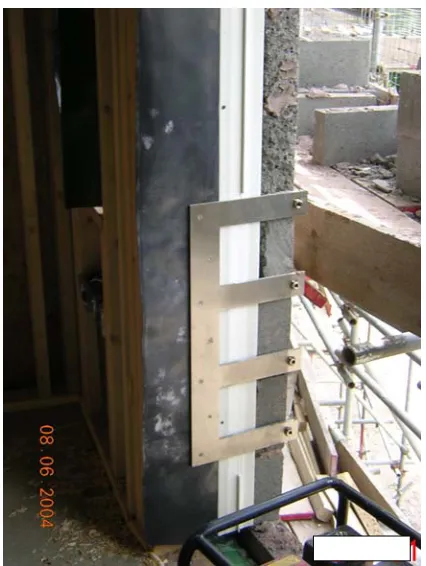
61. In general site observations indicated that a reasonable level of care had been taken to minimise the bridging problems created by through fixings. However for structural reasons fixings for two types of balcony consisted of substantial steel sections that penetrate the insulation layer. Figures 3.33 and 3.34 show some of the fixings used on a partial-fill masonry site and a timber frame site respectively. Although it in not within the remit of this project to carry out the detailed three dimensional analysis that would be required to understand the impact of such fixings, revisions to Robust Details should provide more guidance so that designers are able to minimise the risks involved.
Figure 3.33 Balcony support through partial-fill masonry construction. Internal
concrete floor
External leaf of external wall
Figure 3.34 Balcony support through timber-frame construction.
Windows and door openings
62. Site observations of construction at window and door openings revealed the following general problems:
• Widespread use of uninsulated propriety cavity closers and other problems of closure design;
• Inadequate filling of cavities around openings in masonry cavity construction; • Location of window and door frames with respect to alignment with the insulation
layer;
• High timber ratio to timber frame construction window heads
Cavity closure
Figures 3.35 and 3.36 Uninsulated closers.
64. The use of propriety cavity closers is recognised in the Robust Detail document (see Robust Details 3.12 and 4.12) and where they are used a minimum resistance path of 0.45 m2K/W is specified (based on manufacturer’s certified data)1. While it is recognised that a carefully designed uninsulated closer could achieve this value across its full width, it is highly unlikely that this would be achieved in practice. The minimum frame/cavity overlap is specified as 30mm in the Robust Detail, but this minimum is not always achieved; even where it is adopted 0.45 m2K/W would be very difficult to achieve. A problem with specifying minimums (or maximums) is that it is these figures which are generally aimed for (and therefore often missed, rather than a better standard. Even if a resistance path of 0.45 m2K/W could be demonstrated with an uninsulated closure, the general level of thermal bridging at the sill and jamb is likely to be significant. The modelling phase of this research project will address this issue in assessing the thermal effect as well as condensation risk.
65. Not all sites adopted the propriety closure, some sites using glass or mineral fibre bats wedged into the jamb cavity to be held in place by the window frame as illustrated in figures 3.37 and 3.38 – although from time to time the result was not very pretty. On one site an apparently idiosyncratic mixture of propriety cavity closer and return block was used in the same construction. This is shown in figure 3.39. In this case a well insulated closer was used for the window reveals (a point we discuss below) but in the case of the connected door opening a return block with a rather thin (about 10mm) and ill fitting insulated vertical dpc was used. The impact of the return block is to bypass the partial-fill insulation, resulting in a thermal bridge, the insulated dpc not withstanding.
1 The use of a resistance path calculation to determine the extent of thermal bridging is referred to in the 1995 edition of
Figures 3.37 and 3.38 Alternatives to propriety cavity closers.
Figure 3.39 Inconsistencies in cavity closure detailing.
Return block used, bypassing partial-fill insulation Insulated cavity closer with gap in partial-fill cavity wall insulation
window frame. The calculations involved are highly detailed and there is no evidence from the design material examined that designers gave the problem any consideration at all. Rather, there appears to be a general acceptance that uninsulated closures are adequate. This calls into question the use of the concept but even if the concept were to be retained in further editions of Robust Details, some thought would need to be given to the threshold value for both condensation risk and thermal performance. The value of 0.45 m2K/W is the value adopted for the 1995 edition of the ADL when wall U values were 0.45 W/m2K. Yet as U values fall the significance of bridging increases and one would have expected that Robust Details would have increased the resistance path threshold to accommodate this. As U values fall, further increases in the threshold, or a more fundamental change in the way thermal bridging is dealt with, will be necessary. It is interesting to note that in the review of Part L for 2005 the proposal to include a significantly more rigorous approach to thermal bridging in the Approved Documents and in a revised Standard Assessment Procedure (see draft SAP 2005 – Anderson 2004) may reduce the incidence of this kind of problem.
Cavity fill around openings
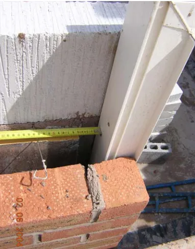
67. The problem of ensuring that full-fill cavities are completely filled with insulation and that partial-fill insulation bats are fitted with no gaps has been generally recognised for some years. The observations in the cases studies provide a number of examples of this problem, particularly around window openings. Figures 3.40 and 3.41 show a fully filled cavity in which the filling work has been completed before the internal blockwork had been completed to sill level. This appeared to be a reasonably common occurrence and although it was not possible to ascertain whether insulation bats were placed in the cavity as blockwork was built up to the sill, it is likely that, at least in some cases, the additional insulation would be missed out. This would lead to increased thermal bridging and, depending on the thermal properties of the internal blockwork, increased risk of surface condensation problems.
Figures 3.40 and 3.41 Blown fibre, full-fill cavity wall insulation at incomplete sills
Figure 3.42 Gap observed between cavity closer and partial-fill cavity wall insulation.
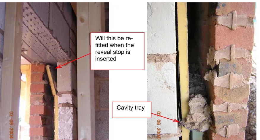
[image:40.612.88.578.357.616.2]Figure 3.44 Partial-fill cavity insulation – gaps and mortar build-up on cavity tray. Will this be
re-fitted when the reveal stop is inserted
Cavity tray
Location of window and door frames
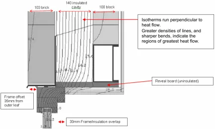
69. The location of the frame with respect to an insulation layer is an important determinant of the extent of thermal bridging, even in otherwise well designed, bridge-minimised, reveals. This point is well illustrated by an analysis of frame location (Roberts, 2004) in the context of a low energy housing scheme (Lowe and Bell, 2002). Figure 3.45 shows the thermal analysis of a head detail produced for one of the house types in the scheme. In its original form the detail adopted the practice advocated by Robust Details (e.g. RD 3.12 figure 3.46) of ensuring a minimum of a 30mm overlap between frame and closer layer. The construction was; 105mm brick – 150mm fully filled (mineral fibre) cavity – 100mm medium density block; separate lintels are used and insulation taken to the back of a liner board so that bridging at the reveal is minimised and the frame set to give a 35mm offset from the front face of the external brick work1. Given a frame depth of 100mm this resulted in the minimum 30mm overlap required by Robust Details.
1 Although it is indicative of reality, figure 3.45 is essentially a simplified model produced for illustrative purposes. The
Figure 3.45 Head detail with a frame offset of 35mm from the outside surface of the outer leaf – detail drawing 031. (source Roberts, 2004)
Figure 3.46 Robust Detail 3.12 – Masonry: Full-Fill Cavity Wall Insulation; Jambs and sills. Isotherms run perpendicular to heat flow.
Greater densities of lines, and sharper bends, indicate the regions of greatest heat flow.
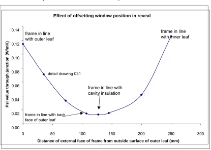
70. Figure 3.47 demonstrates the impact on the linear thermal transmittance (Ψ value1) of different locations of the frame in this detail. The distinct U shape illustrates clearly the impact of shifting the window into line with the insulation. Increasing the overlap to the full thickness of the frame (100mm) results in a significant fall in the Ψ value of the detail. If applied to all openings in the particular house type analysed, the effect of shifting the
1Ψ value is a linear (2 dimensional) thermal conductivity measurement, with units W/mK, and takes into account the
window frame was an improvement in overall wall U value (including thermal bridging) of about 13% (from 0.3 W/m2K to 0.26 W/m2K ).
Figure 3.47 Effect of offsetting window position in reveal on Ψ(psi) value of head junction. (source Roberts, 2004)
Effect of offsetting window position in reveal
0.14
71. Although design drawings, where sufficiently detailed, tended to adhere to the
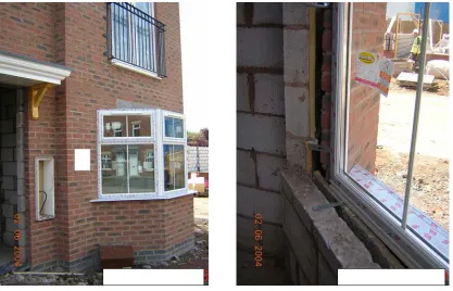
recommendations of Robust Details, site observations suggested practice that was a little more variable with instances of inadequate overlap distances being observed on 5 out of 10 masonry sites where window openings were observed in detail. Where windows are placed in main wall sections, overlap distances of 30 mm were more likely to be achieved than in the case of bay windows. These situations gave rise to particular concern. The more so because they are not explicitly included in the Robust Details document. Figures 3.48 and 3.49 illustrate a typical arrangement in which, having constructed the wall of the bay window, the bay window frame is put into position and secured to the outside leaf of the main wall with reveal straps. This results in the sill being positioned on the outside leaf with very little or no overlap of the frame with the insulation layer at all. This
arrangement must occur also at the window head if the bay continues for another storey. No insulating reveals were stated to be intended, but there was insufficient tolerance to be able to apply a significant insulating layer. The bridging in these locations is likely to be very large with a considerable risk of surface condensation adjacent to the window frames in all areas but particularly at the jamb and head.
0.00 0.02 0.04 0.06 0.08 0.10 0.12
0 50 100 150 200 250 300
Distance of external face of frame from outside surface of outer leaf (mm) frame in line frame in line
with inner leaf with outer leaf
Psi value thro u gh ju ncti on (W /m K)
detail drawing 031
frame in line with cavity insulation
Figures 3.48 and 3.49 No overlap of insulation layer at a bay window.
[image:44.612.94.511.76.344.2]72. Problems of window location and insulation at cavity closures were observed also in steel frame construction. Figure 3.50 shows a door frame set forward of the external insulation layer by about 40mm. Although the insulation is fully taped, as recommended by RD 7.06, the fact that the cavity closure has been pushed well back in to the cavity creates a discontinuity of insulation. This, together with the location of the frame significantly reduces the resistance path from inside to outside. In addition, unless an air/vapour control layer is introduced in the jamb the detail will reduce overall airtightness.
Figure 3.50 Door opening in steel frame construction (as constructed) compared with robust detail 7.06.
Insulation taped to steel frame section Mineral fibre cavity closure set back into the cavity. Location of frame results in large air gap into the cavity
Room-in-the-roof details
increase in the use of pitched roof spaces to provide habitable volume and of the 16 sites visited some 10 sites had dwelling types with habitable space in the roof. Generally, the use of a pitched roof space is geometrically more complex than in other parts of the structure, involving roof lights and dormer windows together with different approaches to providing insulation (eg insulation above the rafters, insulation between the rafters with ventilated battens over, insulation below the rafters) in addition to any different elemental U value standards. Achieving well sealed, bridge free construction presents both
designer and constructor with a considerable challenge as they seek to deal with
awkward junctions involving changes in level, changes of material and varying thickness of base constructions as well as the different angles involved. Despite these complexities the design drawings made available to the research team (and those observed to be in use by operatives) contained few details as to how these areas were to be treated. For example, only one developer provided a large scale detail of construction and fitting of roof windows (a copy of the manufacturer’s standard detail). In other cases operatives were using general arrangement drawings.
74. In attempting to unpick the difficulties for room-in-the-roof construction and observations of construction practice we have identified the following general areas for consideration: • Construction of the main roof structure and fabric;
• Detailing at eaves;
• Detailing around rooflights; • Construction of dormer windows.
Main roof structure and fabric
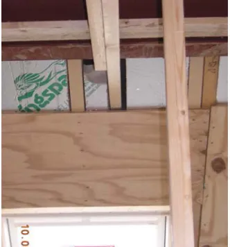
75. The fitting of insulation, particularly when rigid boards were used, was the most common general problem observed, together with the lack of air/vapour control layers in sloping roof sections. Many of the problems were accentuated around roof lights and dormers and the particular difficulties in these areas will be dealt with in those sub sections. The constructions that are most unforgiving if insulation is not tightly fitted tend to be those that adopt a ventilated rafter void with all the insulation fixed between the rafters. Figure 3.51 shows a typical arrangement with 70mm (sometimes as 2 layers of 35mm)
polyurethane foam board fixed between rafters, plywood racking board and 12mm plasterboard finish1. Problems arise with this form of const