© 2017, IRJET | Impact Factor value: 5.181 | ISO 9001:2008 Certified Journal | Page 1096
A Review of Vortex Tube Refrigeration System
Sufiyan Siddiqui
1, Umme Hani Khan
2, Ajit Rakhonde
3, Shaikh Muzammil
41,3,4
Student, Dept. of Mechanical Engineering, STC College, Khamgaon, Maharashtra, India.
2Student, Dept. of Mechanical Engineering, GPK College , Khamgaon, Maharashtra, India.
---***---Abstract –Refrigeration plays an important role in
developing countries, primarily for the preservation of food, medicine, and for air conditioning. Conventional refrigeration systems are using Freon as refrigerant. As they are the main cause for depletion of ozone layer, extensive research work is going on alternate refrigeration systems. Vortex tube is a non conventional cooling device, having no moving parts which will produce cold air and hot air from the source of compressed air without affecting the environment. When a high pressure air is tangentially injected into vortex chamber a strong vortex flow will be created which will be split into two air streams, one hot stream and the other is cold stream at its ends. An experimental investigation is to be performed in order to realize the behavior of a vortex tube system. In this work attention has to be focused on the classification of the parameters affecting vortex tube operation. The effective parameters are divided into two different types, namely geometrical and thermo-physical ones. A reliable test rig is to be designed and constructed to investigate the effect of geometrical parameters i.e. Diameter and length of main tube, diameter of outlet orifice, shape of entrance nozzle. Thermo-physical parameters are inlet gas pressure, type of gas, cold gas mass ratio and moisture of inlet gas.Key Words
:
Vortex Chamber, Refrigeration System, VortexTube Design, Casing, Cooling Effect, Thermal Separation.
1.INTRODUCTION
The vortex tube was invented by a student named G.J Ranque in 1932. He was able to create two streams with different temperatures, using a highly compressed inlet pressure supply. In 1945, a German physicist Rudolf Hilsch improved the vortex tube design of Ranque and he published his work in a scientific paper. This publication of Hilsch was widely read and was very well accepted by the scientific community and thereby the energy separation phenomena in the vortex tube became a topic of great interest. Even though, Hilsch fabricated less than optimized vortex tube geometry, he was able to measure the temperature difference between the inlet stream and the outlet streams; however he was not able to explain the physical process behind this effect. This device was later named the Ranque-Hilsch Vortex tube acknowledging the work done by both G.J Ranque and Hilsch.
Fig -1: Schematic diagram of a Vortex tube and the Phenomena of flow reversal
The vortex tube functions as a device capable of separating a compressed air stream into hot and cold streams with different mass fractions. This phenomenon is referred to as energy (temperature) separation. A vortex tube consists of one or more tangential inlet nozzles, an axial tube with a vortex chamber, a cold gas outlet and a hot gas outlet. Dust free dehumidified compressed air in the range of 5 to 6 bars is injected into the vortex chamber tangentially through the inlet nozzles. As the air accelerates through the inlet nozzles, it exits into a cylindrical section with a high angular velocity which generates an intense swirling flow. The gas then proceeds towards the hot outlet with the conical back pressure control valve. However, not all the flow exits through the control valve. A portion of the gas reverses its direction and moves axially along the center of the tube towards the cold outlet, against the oncoming hot swirling flow.
[image:1.595.310.577.201.381.2]© 2017, IRJET | Impact Factor value: 5.181 | ISO 9001:2008 Certified Journal | Page 1097
1.1. Literature Review
A Review explained the working principle of vortex tube. A detailed description of the parts of vortex tube has been highlighted. Literature review is to understand the effect of various parameters like inlet pressure of air, number of nozzles, cold orifice diameter and hot end valve angle on the performance of vortex tube. Also by the literature review it is clear that there is no theory so perfect, which gives the satisfactory explanation of the vortex tube phenomenon. A detailed study has been carried out to understand the reason of the splitting of air stream. The experimental results show that the static temperature in the center of vortex tube is higher than that of the peripheral part.
Construction design of a vortex tube for several inlet stagnation pressures the report deals with the numerical models used to analyses the geometrical optimization of the vortex tube. Turbulence models like ke model and rans model are briefly described. The main purpose of the work is to increase the amount of energy obtained at cold end.
2. CONSTRUCTION
Fig-2
:
Actual vortex tube2.1. Components Of Vortex Tube
Fig -3: DiagrammaticRepresentation of Vortex Tube
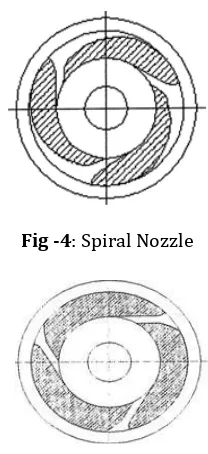
2.1.1. Nozzle
A nozzle is a device designed to control the direction or characteristics of a fluid flow (especially to increase velocity) as it exists (or enters) an enclosed chamber or pipe.
Fig -4: Spiral Nozzle
Fig -5: Nozzle of normal rectangle
2.1.2. Diaphragm
A diaphragm is a sheet of a semi flexible material anchored at its periphery and most often round in shape. It serves either as a barrier between two chambers, moving slightly up into one chamber down into the other depending on the differences in pressure, or as a device that vibrates when certain frequency are applied to it.
2.1.3. Valve
A device used for controlling the flow of fluid in the pipe or other enclosure. Control is by means of a movable element that opens, shuts, or partially obstructs an opening in passage way.
2.1.4. Hot air side
Hot side is cylindrical in cross section and is of different length as per design.
2.1.5. Cold air side
Cold side is cylindrical portion through which cold air is passed.
2.1.6. Chamber
[image:2.595.380.484.164.391.2] [image:2.595.36.288.385.549.2] [image:2.595.36.291.613.751.2]© 2017, IRJET | Impact Factor value: 5.181 | ISO 9001:2008 Certified Journal | Page 1098
chambers noncircular form, but they are gradually converted into spiral form.
2.1.7. Diffuser
Diffuser is the device that allows the high velocity air to expand and lowers the temperature as well as pressure of the air. By the installation of a diffuser it affects the temperature of cold air.
3. DESIGN AND CONSTRUCTIONAL FEATURES
In general, there are two design features associated with a vortex tube, namely, maximum temperature drop vortex tube design for producing small quantity of air with very low temperatures and maximum cooling effect vortex tube design for producing large quantity of air with moderate temperatures. These two design considerations have been used in study for increasing the heat transfer rate during forward motion for swirl air and reversed flow of axial air. The parameters investigated in the study, to understand their inter-relationships and their effect on the performance of the vortex tube are:
Nozzle diameter
Cold orifice diameter
Length of the tube
[image:3.595.309.575.159.361.2] Area at the hot end
Fig -6:Modified Casing of Vortex Tube
4. Material Used For Vortex Tube Components
The material for cold end (inlet cap) is MS, while the hot end is manufactured in Brass for its good thermal conductivity and rest of part are manufactured in mild steel for reducing its overall cost and machining cost. A vortex tube of size 11.04 mm diameters of MS was selected. The casing of the vortex tube was a 27 mm long MS cylinder. Two sets of nozzles were made and each set consisted of two nozzles. The first set of nozzles had a 32.7 mm diameter hole and was 21 mm long, whereas the second set nozzles had a 33.0 mm Outer diameter and was 12 mm long. Similarly, two cold orifices are used having taper hole diameters from 4.5 mm to 9.0 mm, respectively. A conical valve made of mild steel was
provided on the right hand side of the tube to regulate the flow.
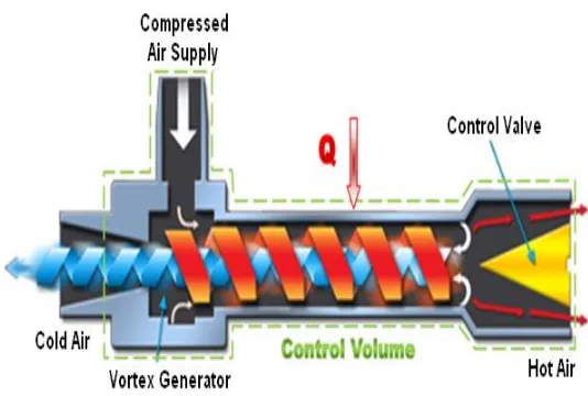
[image:3.595.43.275.440.563.2]5. WORKING
Fig -7: Working of Vortex Tube
Compressed air is passed through the nozzle as shown in Fig. Here, air expands and acquires high velocity due to particular shape of the nozzle. A vortex flow is created in the chamber and air travels in spiral like motion along the periphery of the hot side. This flow is restricted by the valve. When the pressure of the air near valve is made more than outside by partly closing the valve, a reversed axial flow through the core of the hot side starts from high-pressure region to low-pressure region. During this process, heat transfer takes place between reversed stream and forward stream. Therefore, air stream through the core gets cooled below the inlet temperature of the air in the vortex tube, while air stream in forward direction gets heated up. The cold stream is escaped through the diaphragm hole into the cold side, while hot stream is passed through the opening of the valve. By controlling the opening of the valve, the quantity of the cold air and its temperature can be varied.
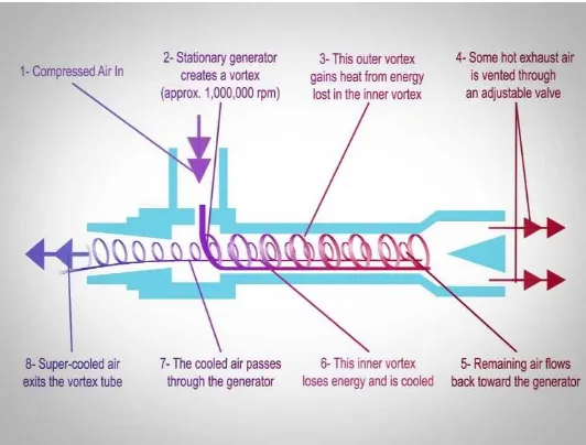
5.1. Temperature Separation Effect
© 2017, IRJET | Impact Factor value: 5.181 | ISO 9001:2008 Certified Journal | Page 1099 mass. The inner air stream flows through the hollow core of
[image:4.595.38.290.180.310.2]the outer air stream at a slower velocity than the outer air stream. Since the energy is proportional to the square of the velocity, the cold air stream loses its energy by heat transfer. This allows energy to flow from the inner air stream to the outer air stream as heat creating a cold inner air stream.
Fig -8:Temperature Separation in Vortex Tube
6. CLASSIFICATIONS OF THE VORTEX TUBE
Generally, the vortex tube can be classified into two types. One is the counter-flow type (often referred to as the standard type) and the other the parallel or uni-flow type.
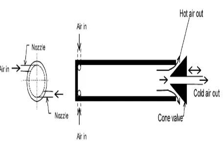
6.1. Counter-flow vortex tube
Fig -9:Counter-Flow Vortex Tube
The counter-flow vortex tube, as shown in Fig 9 consists of an entrance block of nozzle connections with a central orifice, a vortex tube (or hot tube) and a cone-shaped valve. A source of compressed gas (e.g. air) at high pressure enters the vortex tube tangentially through one or more inlet nozzles at a high velocity. The expanding air inside the tube then creates a rapidly spinning vortex. The air flows through the tube rather than pass through the central orifice located next to the nozzles because the orifice is of much smaller diameter than the tube. The length of the tube is typically between 30 and 50 tube diameters, and no optimum value has been determined between these limits. As the air expands down the tube, the pressure drops sharply to a
value slightly above atmospheric pressure, and the air velocity can approach the speed of sound. Centrifugal action will keep this constrained vortex close to the inner surface of the tube.
The air that escapes at the other end of the tube can be varied by a flow-control valve, usually shaped as a cone. The amount of air released is between 30% and 70% of the total airflow in the tube. The remainder of the air is returned through the centre of the tube, along its axis as a counter-flowing stream. Once a vortex is set up in the tube, the air near the axis cools down while the air at periphery heats up in comparison with the inlet temperature. This phenomenon is known as temperature separation effect (also called the Ranque–Hilsch effect). As a result, the gas escaping through the orifice is cold and the hot gas flows out in the other direction. A remarkable feature of this device is the absence of moving parts and simplicity of operation.
[image:4.595.316.545.344.489.2]6.2. Uni-flow vortex tube
Fig -10:Uni-Flow or Parallel Flow Vortex Tube
[image:4.595.44.273.446.574.2]© 2017, IRJET | Impact Factor value: 5.181 | ISO 9001:2008 Certified Journal | Page 1100
7. ADVANTAGES
1. It uses air as refrigerant, so there is no leakage problem. 2. Vortex tube is simple in design and it avoids control
systems.
3. There are no moving parts in vortex tube. 4. It is light in weight and requires less space.
5. Initial cost is low and its working expenses are also less, where compressed air is readily available.
6. Maintenance is simple and no skilled labours are required.
8. DISADVANTAGES
1. It has low co-efficient of performance COP.
2. It has limited capacity and only small portion of the compressed air appearing as the cold air limits its wide use in practice.
3. Only used for spot cooling purpose. 4. Required low pressure range.
9. APPLICATIONS
5.
1. Vortex tubes are extremely small and as it produce hot as well as cold air. It may be of use in industries where both are simultaneously required.
2. Temperature as low as –500C can be obtained without any difficulty, so it is very much useful in industries for spot cooling of electronic components.
3. It is commonly used for body cooling of the workers in mines.
4. Vortex tubes are used for cooling of cutting tools (lathes and mills, both manually-operated and CNC machines) during machining.
5. Commercial vortex tubes are designed for industrial applications to produce a temperature drop of up to 71 °C (127 °F). With no moving parts, no electricity, and no Freon, a vortex tube can produce refrigeration up to 6,000 BTU/h (1,800 W) using only filtered compressed air at 100 PSI (6.9 bar). A control valve in the hot air exhaust adjusts temperatures, flows and refrigeration over a wide range.
10. ASSUMPTIONS
1. The working medium is ideal gas-air.
2. There is no heat interaction of the computation domain with the surroundings.
3. Flow is steady, turbulent and compressible. 4. Body force is negligible.
11. CONCLUSIONS
A simple model of the Vortex Tube is described that captures the physics related to one possible operating mechanism.
The model is shown to faithfully reproduce a limited set of data if two empirical parameters are adjusted. The semi-empirical model is subsequently used to evaluate the potential performance benefit associated with replacing the throttling valve in a refrigeration system with an approximately optimized Vortex Tube. An experimental study on the temperature separation in the Vortex Tube has been carried out and this research finding can be summarized as follows:
1. Temperature difference increases with increase in Inlet Pressure.
2. Availability destruction decreases with increase in tube length due to the increase in temperature difference. 3. Efficient working point of the existing design is at a cold
mass fraction 0.84 for an inlet pressure of 5bar. 4. Availability destruction is less in the case of Vortex Tube
operation with two nozzles than with one nozzle due to the increase in temperature difference.
5. The increase of the number of inlet nozzles led to higher temperature separation in the Vortex Tube.
6. Using the tube with insulation to reduce energy loss to surroundings gave a higher temperature separation in the tube than that without insulation around 2-3℃ for
the cold tube and 2-5℃ for the hot Tube.
7. The performance of a conventional vapor compression refrigeration cycle cannot be augmented through the application of a Vortex Tube because no temperature separation can occur beneath the vapor dome.
8. The performance of a vapor compression cycle operating in the near supercritical region, such as carbon dioxide refrigeration cycle, is negligibly increased by the application of a Vortex Tube.
12. FUTURE SCOPE
As we all know there are no limits for improvements in any kind of work or we can say nothing is best. There is always scope for improvements in present work. So, Vortex tube is not an exception. Several investigators have modified the in geometric design of present vortex tube and tested for better performance. But there are still so many options available on which experiments can be done. After some experimental analysis work studied which is done by various researchers, on geometrical modifications for improving the performance of vortex tube are as listed below:
1. We can increase number of inlet air entries.
2. Guiding element inside the Vortex tube can be provided
for guiding inlet air circumferentially towards hot end.
3. Experiments are also possible with varying the length of
Cold ends and Hot ends.
4. Same Vortex tube as we have manufactured can be
tested by using water as cooling agent.
5. We can try some modification in the geometry of
© 2017, IRJET | Impact Factor value: 5.181 | ISO 9001:2008 Certified Journal | Page 1101
6. We can try the same geometry in different material and
compare it to find the dependency on material of the vortex tube.
ACKNOWLEDGEMENT
I take this opportunity to express my heartfelt gratitude to my guide Prof. Mandar Tawlarkar and head of department, Prof. Anand Paralkar, department of Mechanical Engineering, STC school of poly, Khamgaon, for her kind co-operation, constant Encouragement and suggestion and capable guidance during the research without which it would have been difficult to proceed with.
REFERENCES
[1] G. J.Ranque, “Method and apparatus for obtaining from a fluid under pressure two outputs of fluid at different temperatures,” 1934.
[2] G.W.Scheper, “The vortex tube; internal flow data and a heat transfer theory,” 1951.
[3] Ahlborn and S. Groves, “Flow in a vortex tube,” 1997. [4] Marquesa C.H., Isoldia L.A., Santos E.D. Rocha L.A,
‘‘Constructional Design of a Vortex Tube,’’2002. [5] Prof. U.S.P. Shet, Prof. T. Sundararajan and Prof. J.M.
Mallikarjuna, “Working, application & advantages of vortex tube,” 2004.
[6] N.Pourmahmoud, S.Akhesmeh, “Numerical Investigation of the Thermal Separation in a Vortex Tube” 1998. [7] R. Shamsoddini, A. H. Nezhad, ‘‘Numerical analysis of the
effects of nozzles number on the flow and power of cooling of a vortex tube, 2010.
[8] S. Nimbalkar and M. R. Muller, “An experimental investigation of the optimum geometry for the cold end orifice of a vortex tube, Applied Thermal Engineering,” 2009.
[9] Ahlborn, B. and J. Gordon, “The vortex tube as a classical thermodynamic refrigeration cycle,” 2000. [10] A Textbook of Refrigeration and Air Conditioning by
Arora & Domkundwar, Section No 2.1, 8.2, 10.8. [11] Refrigeration and Air Conditioning by R. S. Khurmi,
Section No 1.1, 15.2
BIOGRAPHIES
Sufiyan Siddiqui is a final year student in Mech Department, STC school of poly, Khamgaon MS. His research interest is Vortex Tube Refrigeration System
Umme Hani Khan is a final year student in Mech Department, Government poly, Khamgaon MS. His research interest is Vortex Tube Refrigeration System
Ajit Rakhonde is a final year student in Mech Department, STC school of poly, Khamgaon MS. His research interest is Vortex Tube Refrigeration System