© 2017, IRJET | Impact Factor value: 5.181 | ISO 9001:2008 Certified Journal | Page 220
Evaluating Static Analysis of the Damper Grommets for Compressor
Vivek P
1, Dr. B Ravindra
21
Deparment of Mechanical Engineering, Dr Ambedkar Institute of Technology, Karnataka, India
2
Professor
, Department of Mechanical Engineering, Dr Ambedkar Institute of Technology, Karnataka, India---***---Abstract –
Ain basically the grommets are hole string likestructures made up of rubber and many other elastic materials these are mainly used to reduce the vibration of the reciprocating machines. Especially in the house holding refrigeration and air cooler. In refrigeration working condition the compressor are producing some noise. This sound is irritating the people in the house. When the compressor are in working it compress the water with low or high pressure and it reciprocates the weight of the compressor is directly applied on the base plate. When compressor in static condition whole weight of the compressor is fully applied force on the grommets. But the application of force grommets vary the with the static response with respect to the load. In this type of grommets material is vulcanized rubber prepared by ASTM D412 test method. The value of the grommets vary with material properties and especially considering the displacement and the stress. The displacement results obtained from the testing is notified. And we are simulating the grommets position vary with the loads. And finding the values of the displacement and stress value of the simulation method .and this simulation is done by ABAQUS software. Finally compare the both the displacement and stress value.
Key Words: grommets, compressor, vibration, static
response, ASTM D412, simulation, displacement, stress,
1.
INTRODUCTION
Compressors are the fundamental hardware of refrigeration units, for example, ventilation systems and coolers. Responding compressors are one of the for the most part utilized sorts of compressors since they can accomplish a high weight proportion at a low vitality input. In any case, the cyclic development of cylinders in the responding compressors brings about mechanical vibration that can cause undesirable commotions. To dispose of the commotion, grommets are introduced as auxiliary backings for confining the vibration sources, i.e., the compressors, from the beginning. The grommets are normally or essentially made of elastic since they have adequate solidness to withstand the heaviness of the compressors and can diminish the size of vibration by scattering the vibration vitality as warmth while being consistently deformed.4
Fig-1 Compressor Used In Small Commercial Refrigeration
To limit the clamour, grommets are introduced as auxiliary backings for disengaging the vibration sources, i.e., the compressors, starting from the earliest stage. The grommets are essentially made of elastic since they have adequate solidness to withstand the heaviness of the compressors and can lessen the size of vibration by disseminating makers, while the grommet makers just fill in as made-to-arrange providers. To build the estimation of grommet and to limit the assembling cost, an orderly grommet plan system must be produced for the business.
Fig-2 Common features of a rubber grommet
© 2017, IRJET | Impact Factor value: 5.181 | ISO 9001:2008 Certified Journal | Page 221
A grommet has a top head and an opening for embeddinginto a gap at the base of a compressor.
The part beneath the opening is the shoulder territory for resting the base piece of a compressor,
The part under the shoulder is the base, and
At the mid piece of a grommet there is an opening for embedding a jolt that bolts the grommet to the ground support of the compressor
1.1
Materials used to produce grommets
Collection of material are used to create grommets, for instance, metal, plastic, and versatile materials. Metal is the primarily used materials. It gives awesome quality, and staggering high temperature malleability, sensible cold adaptability, extraordinary bearing properties and low appealing permeability, incredible electrical conductivity, astonishing disintegration resistance, Nickel composites contain nickel and no less than one distinct metals, for instance, copper. Steel, a business press contains carbon in any entirety up to around 1.7 percent, is flexible under suitable conditions and perceived from cast press by the two its flexibility and lower carbon content. Stainless steel is engineered and utilization safe and can have respectably high weight assessments. Butyl, a run of the mill term for the isobutylene isoprene elastomer, is impenetrable to water, steam, dissolvable bases, and oxygenated solvents. Butyl has low gas entrance and high-imperativeness osmosis (hosing) and moreover incredible hot tear quality. Styrene Butadiene Rubber (SBR) and Nitrile are used with most oils, water driven fluids and alcohol. A many sorts of select blends are open for specific applications.
1.2
How to Select a Grommet
Assurance of grommets requires an examination of some physical points of interest. Inside width (ID) is the opening breadths through the center reason for the grommet. Wrinkle width related to the thickness of the material into which sort grommets are inserted. Inside separation crosswise over of the grommets is called woods estimation. Other physical conclusions are considered for grommets join as a rule and outside separation crosswise over (OD) or length, thickness. Width is a fundamental physical estimation for oval, oval, square and rectangular sort grommets. The units for measuring the grommets in inches (in). Centimeters (cm) moreover used to gage the grommets
1.2.1 Standards
Promotions AS1902 - Cable grommets
Promotions AS44404-406 - Elastomeric grommets (different), for aeronautical purposes
AN231 - Grommet and waste, plastic
1.3
Application of rubber grommets
he Elimination of Sharp Edges Aesthetic appeal
Varied Sizes Water Resistance Vibration Damping Desk Grommets
2. MATERIAL PROPERTIES
2.1.1 Measuring Material Properties
Since the state of elastic grommets does not permit standard test techniques for measuring material properties, a demand is made to the grommet maker to give the elastic in a type of a sheet. The elastic sheet is tried under two conditions: the versatile properties are measured from uniaxial tractable tests and the gooey properties are measured from push unwinding tests. The two tests utilize elastic examples arranged by ASTM D412. The tractable test examples are stacked at a crosshead speed of 500 mm/min. The unwinding tests are led by at first extending the example to a 25% ostensible endure a speed of 500 mm/min and afterward holding for 600 seconds. The test outcomes appeared in Fig. 6 and 7 for the ductile test and the unwinding test demonstrate a run of the mill nonlinear time-subordinate conduct of an elastomer
2
EXPERIMENTAL PROCEDURE
Fig-3 standard type of universal testing machine
© 2017, IRJET | Impact Factor value: 5.181 | ISO 9001:2008 Certified Journal | Page 222
Analysis obtained:Stress at specified or required elongation Tensile or compressive Yield Stress Tensile or compressive Yield Strain
Tensile or compressive Strength at Rupture or break point Elongation of the Rupture
Equipment required:
1. Universal testing machine (tensile testing machine) is the basic testing machine to finding the any of the material property related to the material with the fallowing specification
A. Servo-controlled is the basic device to maintain the constant speed .the rate of speed to(+/-2inches/min) B. minimum 30 inches of crosshead travel with high
elongation materials
C. Most common 1kN (225 pound) load carrying capacity machines is required to the tested machine.
The larger part of our eXpert2600 course of action twofold segment machines meet these essentials, and it is in like manner standard to use our single section eXpert7601 XL with 53 creeps of crosshead travel.
2. An extensometer is optional however recommended. We recommend one for two reasons. To begin with, dumbbell cases don't have uniform widths which cause goofs when both the wide and limited ranges of the dumbbell framed case reach out at different rates. Besides, prolongation is regularly a basic layout typical for rubbers and elastomers so an extensometer can be used to upgrade exactness of the estimation.
3. Programming or sensible devices are required to work the machine and to take the estimations. Major systems will give the unrefined data, and stress-strain diagrams. Using these wellsprings of data, you can choose and learn most of the examination recorded beforehand. Nevertheless, totally PC based structures can figure these normally. For example, our MTEST Quattro testing programming has worked in help for ASTM D412 and these calculations are given rapidly consequent to playing out the test.
4. Pliant handles hold your case in the midst of the test as it is being pulled isolated. Elastomers speak to a test to hold since they thin as they are extended. Likewise, by a wide margin the greater part of elastomers ought to be held with self-settling holds. Instances of these holds are odd roller handles, wedge holds, or pneumatic handles. Regardless of the hold design, the thought is the same - they settle on the material as it decreases to keep predictable constrain on the case.
Specimen identifier 6
Width 0.25150 in or 6.3881 mm
(1inch =25.4mm)
Thickness 0.1028 in or 2.6112mm
Axial strain gauge length 1.00 in 25.4mm
Area 0.0269sq in or
0.17.3548sqmm
Maximum Load 17.64lb or 78.466 N (1lb =4.4482N)
Analysis results ASTM D412
Tensile or compressive yield stress 661.0 psi or 4.5574 N/mm2
Tensile or compressive yield strain 4.636 in Tensile or compressive rupture or breaking strength 678.0 psi or 4.674 N/mm2
Auto elongation at break
Gauge length 1.00in or 25.4mm
Elongation 454.49%
Young’s modulus 0.01 to 0.1Mpa
Fig-5 Stress strain curve of the ASTM D412
3 Theoretical Calculations
3.1 Finding the density of the selected rubber grommet
Fig-6 Geometric parameter of the grommets
© 2017, IRJET | Impact Factor value: 5.181 | ISO 9001:2008 Certified Journal | Page 223
subtracted total volume by inner radius of inner volume weget the reaming volume is the grommets volume
Density of the grommet (ρ) = volume of the grommets (v) / total mass of the grommets (m)
ρ = v/m 3.83/ 12.8
1447 mm3 (or) 1.447 tons / mm3
4. OBJECTIVES AND METHODOLOGY
4.1 Objectives
The principle destinations of the present work is to explore the impact of static and dynamic examination of grommets for responding compressor .keeping in mind the end goal to finding the aggregate impact of vibration reaction of the compressor mounting framework
Analyze the vibration reaction of grommets of responding compressor utilized as a part of little refrigeration
Determine the significant basic repeat of the mounting vibration structure in each one of the an essential bearing
Finding the statically analysis values and the compressor mounting in the materials
Analyzing the behavior of the grommets in the in static condition
Comparison of the results with the simulation results
5 METHODOLOGY
5.1 Problem Definition
The goal of this venture is to investigations and enhance geometry of elastic grommet for compressors utilized as a part of little coolers. The elastic grommets are utilized as vibration isolators that diminish the greatness of vibration because of the intermittent movement of dynamic segments in the compressors
5.2 Flow Chart for Methodology
Creating a geometric model of Grommets in SOLIDE WORKS
The weight of compressor is modeled as lumped mass at its CG location.
Discretizing geometric model using ABAQUS Application of loads and boundary condition Linear static and structural analysis using
ABAQUS
Finding the results of the analysis solution Comparing the analysis results with experimental
and simulation results
5.3
Cad Model
Fig-7 Geometric modeling of Grommet
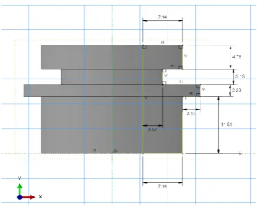
Fig-8 Front and top view of Grommet
5.4 Meshing
Figure 9 shows the Finite Element model generated for the geometric model of the Grommet structure using linear hexahedral elements. These elements are selected because the quadratic result interpolation at the integration point.in this messing element number of elements are used to finding the value of the applied force on the grommet base. Mainly the process of messing is to discretizing the elements in to many equal number of elements. And the elements are considering the equal in size and shapes
[image:4.595.259.542.85.438.2]
Table No. 4.1 Elements and nodes count
TYPE OF ELEMENT linear hexahedral
elements (C3D8R) TOTAL NUMBER OF NODES 20448
TOTAL NUMBER OF
[image:4.595.350.535.124.275.2]© 2017, IRJET | Impact Factor value: 5.181 | ISO 9001:2008 Certified Journal | Page 224
Fig-9 Mesh model of Grommet5.5
Assembly of Meshed Grommet
Fig-10 Assembly of the grommets with BC
The distance between the two grommets is 102 mm and the length is of 165 mm. The CG point is located at 64mm to X axis and 34 mm to axis and 50mm to Y direction
5.6
Loading Condition
Fig-10 Loading condition of grommets
The load of compressor of 8.41kg is applied on CG point. The tie boundary condition is applied to the inner surface of the grommets to the BC point. Gravity acts along the -ve Y axis for all the grommets.
6 RESULTS AND DISCUSSION
6.1 Linear Static Analysis
The FE model of grommet structure with loads and boundary conditions was run for analysis in ABAQUS
.
6.1.1 Displacement Plot for Static Analysis
The FE model of grommet structure with loads and boundary conditions was run for analysis in ABAQUS. The following figures give the results of both static and model analysis. For static analysis displacements and stresses are obtained and for model analysis different modes of frequencies are obtained.
Fig-11 Displacement plot for static analysis
6.1.2 Stress Plot for Static Analysis
Fig-12 Stress plot for static analysis
7 CONCLUSION AND FUTURE SCOPE
7.1 Conclusion
The maximum stress in the segment is found in the experimental 4.58Mpa and in the simulation result is 1.2Mpa.
© 2017, IRJET | Impact Factor value: 5.181 | ISO 9001:2008 Certified Journal | Page 225
And also considering the elongation of this rubbermaterials is 454 percent elongation is possible. The simulation stress is within failure stress and the
rubber grommet is safe.
Displacements are found to be within limits in experimental 4.5 mm and after simulation 1.5 mm
7.2 Scope of Future Work
Reduce the stiffness of the grommet because low stiffness are not always desirable and thy are sustain weight of the compressor
Determine the fatigue life of the grommets Finding the product life cycle of the grommet Dynamic response analysis shell be performed for
the input acceleration spectrum.
Optimizing the given results using the mechanical softwar
REFERENCE
[1] Zaidi Mohd Ripin and Ooi Lu Ean, Dynamic characterization of engine mount at different orientation using sine swept frequency test. Regional Conference on Mechanical and Aerospace Technology Bali, February 9 – 10, 201.
[2] Aleks Kuyumcuoglu, Ozgun Sakalli Arcelik A.S. Ankara Asfalti investigation of vibration transmission Properties of compressor grommets in Domestic refrigerators
34950 Tuzla, Istanbul, Turkey
[3] Embraco, Carlos Eduardo Vendrami Analysis of Vibration Isolators for Hermetic
Compressors Brazil, Claudio Pellegrini
[4] G. Lampugnani Aspera Compressor Noise Reduction on a Refrigerator 1994 Yuki Tanaka*, keigo matsushima, Yoshinao kobayashi, Masaru shitamichi,
[5] Koji miyajima, hidemi Tanigawa and koji ota Practical Use of Computer-Aided Engineerin in the Development of Automotive Rubber Grommets
[6] Xianpai Zeng, Jared Liette, Scott Noll, and Rajendra Singh Analysis of Motor Vibration Isolation System with Focus on Mount Resonances for Application to Electric Vehicles Ohio State University
[7] David Koblar1, Miha Bolte_zar2 Evaluation of the frequency-dependent Young's Modulus and damping factor of rubber from Experiment and their implementation in anite-element analysis
[8] T. S. Dol*, D. N. Korade, P. D. Darade, K. R. Jagtap Narhe, Design Development and Testing of Hydraulic Engine Mount