© 2017, IRJET | Impact Factor value: 5.181 | ISO 9001:2008 Certified Journal | Page 2674
CASE STUDY ON FLYOVER AT NASHIK ON NH-3
Rahul Shewale
1, Bhagyashri Dhande
2, Amol Gavit
3, Rahul Asware
4,Hitesh Patil
5, Tushar Mali
61Lecturer, Department of Civil Engineering, MET Institute of Technology (P), Nashik, M.H., INDIA 2HOD, Department of Civil Engineering, MET Institute of Technology (P), Nashik, M.H., INDIA 3456Diploma Student, Department of Civil Engineering, MET Institute of Technology (P), Nashik, M.H., INDIA
---***---Abstract -
Today in this 21st century the population is growing at a tremendous rate and thus the roads used for transportation is becoming narrower for the increasing population. This causes more and more traffic in the city/roads. This traffic blocks, consumes much time of transportation, and thus why there is a rise or we can say need for evolution or expansion so that we can come over the problem of the traffic blocks and there management. Thus bypasses and flyovers are one of the solutions for it. flyover with an expanded road as compared to actual road is thus the topic of our case study This case study will address the details and construction of a segmental box girder bridge utilizing the balanced cantilever method of erection for the elevated corridor for Pimpalgaon-Nashik-Gonde project in Maharashtra.Key Words:Piers, foundation; Post-Tensioned; Segmental Box Girder; Knee Braces
1. INTRODUCTION
The work has been awarded to M/s Larsen & Toubro-M/s Ashoka Buildcon Limited Consortium and agreement is signed with the Concessionaire M/s L & T- PNG Tollway Private Limited, on 8th July, 2009. Design & Preconstruction activates are in progress. Work is expected to be started in January, 2010. The construction period is 30 months (including monsoon period.) Project envisages up gradation of existing 2 lane carriageways to 6 lane divided carriageway i.e (3-lane on each side) configuration with 5m wide median at centre. This project involves construction of 5.50 km long (4lane) flyover for through traffic flying over four busy junctions viz. Aurangabad Naka Junction, peth Junction, Dwarka Junction & Mumbai Naka. Along this 5.5 Km long flyover, 4 lane divided carriageway at grade road in addition to 2-lane service road on either side (total 12-lane carriageway within the city portion) with Up/Down ramps at Dwarka Junction where NH-50 meets with NH-3 are being provided. The Pimpalgaon Nashik Gonde mad project serves with a elevated corridor, seven flyovers, two major bridges, six vehicular under passed, six pedestrian under passes, six pedestrian under passes and a subway. The flyover passing through Nashik city a Pathardi is India’s longest integrated flyover. The Elevated Corridor in Nashik is India’s first externally strutted segmental box girder. The Pimpalgaon Nashik Gonde road project is a six lane, 60 km route built at a cost of Rs. 940 cores. The Elevated Corridor is the second longest flyover in Maharashtra. (The longest flyover-the Mumbai eastern highway, was inaugurated in Mumbai on June 13, 2013, a day before flyover-the Nashik elevated corridor). The Nashik flyover stands on 172 pillars with 12 segments each. It is made up of 2064 segments. The strutted segmental technique was first used for a bridge in Bangkok. The Elevated Corridor in Nashik is the second of its kind in Asia and first in India. The design of the flyover and its technique strengths it to bear heavy load capacity and increases its life up to 100 years. It has been categorised as ‘A Class’ loading design. The Elevated Corridor also gives the city 12 lane road for traffic passing through the city. The flyover from Mumbai Naka to Adgaon is four lanes, it has four lane grade roads on both the sides and below this is the four lane service road. Four flyovers are in the Nashik Municipal corporation limit and two are outside it. There are 8 underpasses beneath these flyovers that will facilitate city traffic movement. A part from these flyovers it has two major bridges and 11 small bridges and a subway. There are 34 bus bays and 4 Truck lay byes. The project has been delayed by about a year and some underpasses are yet under construction.
2. OBJECTIVES OF THE STUDY
To understand the structural features of flyover.
To understand method of construction by using precast box girders.
© 2017, IRJET | Impact Factor value: 5.181 | ISO 9001:2008 Certified Journal | Page 2675
4. METHODOLOGY
The segments are transported to the site from the P.C. yard then at the site there is launcher resting on two piers. First of all segments ES1 and RS1 are lifted then each consecutive segments are lifted with the help of launcher from both the piers towards the centre of the span. For joining the two consecutive segment gluing material is used which consist of epoxy resin and hardener. These two elements after mixing with each other are to be applied within 2 hrs. Only.
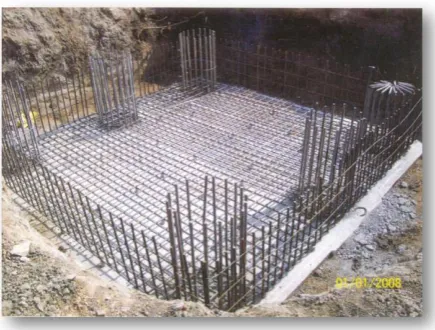
4.1 FOUNDATION
The types of foundation mainly used are as follows: Open foundation
Pile foundation
[image:2.595.224.442.381.546.2]
Fig 4.1: Foundation of pier
The selections of type of foundation depends upon the standard penetration number followed by standard penetration test, following conditions were considered while deciding the type of foundation:
If span is greater than 50, then open foundation is used at the particular place.
If span is less the 50 then use pile foundation is used at the particular place.
The Concrete used for foundation is of M35 grade. The concreting work is done by time method.
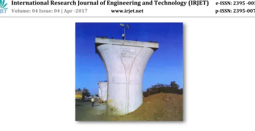
4. 2 PIERS
The piers are mainly of two types 1. Fixed pier
© 2017, IRJET | Impact Factor value: 5.181 | ISO 9001:2008 Certified Journal | Page 2676 Figure 4.2 Pier at the site
The fixed pier carry’s dead load and moments whereas the free pier carry’s only dead load Position of piers are such that they are alternately placed such as one fixed pier & one free pier. Shape of pier, the area is larger at top and that is obtained by providing parabolic curve at upper side of the pier. The height of the pier above the ground level excluding the pier cap is 350mm. A pier cap is also provided of 500mm thickness at the top of pier. The main reason behind such an arrangement is that the free pier provides space for shacking & while the fixed pier is rigid and firm. The average distance between the two consecutive piers is 30m.
Following activities are carried out while casting of pier
Steel reinforcement
Placing the shuttering for pier, the shuttering is made of steel.
Concreting with RMC and boom placer.
Removal of shuttering after the 24 hrs. of concreting
White wash (lime) is applied to pier so as to maintain the heat of hydration & balance the chemical reaction and also it is dressed with jute sheets.
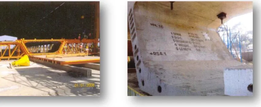
4.3 SEGMENTS
[image:3.595.195.431.606.729.2]Segments are the heart and soul of this elevated corridor, there details are as follow:
© 2017, IRJET | Impact Factor value: 5.181 | ISO 9001:2008 Certified Journal | Page 2677
23.1m-2 no of span.
21.865m-1 no of span.
Above figures are including the ramps at various junctions. There are in all total 171 no of span. Specific name or we can say designation is given to every span. 12 segments are placed between two consecutive piers covering a span of 30m Length of each segment is 19.7m approximately.
There specification ore as follows:
Es-2(parabolic) 1.5m in width, web thickness – 600mm, 2Nos.
Rs1-2(parabolic) 1.5m in width, web thickness – 600mm, 2Nos.
Rs2-2(parabolic) 3m in width, web thickness – 600mm, 2Nos.
Rs3-2(parabolic) 3m in width, web thickness – 600mm, 350mm (varying thickness) 2Nos.
Rs 4-4 (straight) 3m in width, web thickness-350mm. 4Nos.
Fig - 4.4: Formwork of the Segment at the casting yard
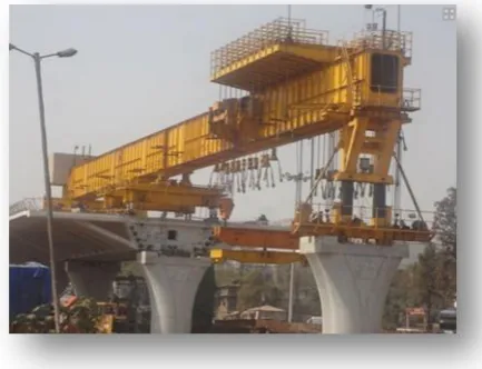
[image:4.595.88.514.383.557.2]© 2017, IRJET | Impact Factor value: 5.181 | ISO 9001:2008 Certified Journal | Page 2678 Fig - 4.5: Segment being lifted ad placed Fig - 4.6: Placing of segment in order
Fig - 4.7: Segment being placed in position Fig-4.8: Final view of an span
4.4 ADVANTAGES AND DISADVANTAGES
4.4.1 ADVANTAGES
As it is said infrastructure plays very important role in growth of nation thus this infrastructure project is important for national growth from infrastructure point of view
Due to precast methods used much time is saved and speedy construction activities are carried out.
Less Hindrance to traffic
4.4.2 DISADVANTAGES
Many trees were cut during the project so it indirectly affects the environment.
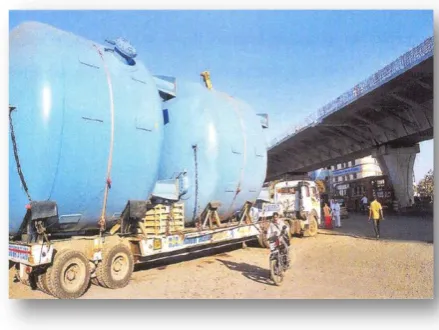
[image:5.595.41.253.319.488.2]© 2017, IRJET | Impact Factor value: 5.181 | ISO 9001:2008 Certified Journal | Page 2679 Fig 5.1: very big container at Dwarka Circle
Big container making problem at the Dwarka junction.
5. CONCLUSTION
Precast segmental construction is a versatile technique for construction of present day fast track jobs.
Segments can be cast away from actual site, thereby minimizing hindrance to traffic & public in urban environment.
In casting yard better control on quality & dimensional tolerances can be achieved. Segment casting can start independently as work on foundations progresses, their-by reducing overall completion time.
Segmental construction technique has been a very effective and economical technique in above situations.
This project will add beauty to the Nashik city with its appealing aesthetics.
Selecting innovative design concepts and construction methodologies can tackle problems occurring in construction. A well-conceived construction mythology can result into least traffic disturbance, construction delays and noise & visual pollution.REFERENCES
Prof. Dr.-Ing. G. Rombach, “Precast segmental box girder bridges with external prestressing - design and construction” Technical University, Hamburg-Harburg, Germany.
Information Brochure of National Highway Authority of India of PNG Toll ways Pvt Ltd VOLUME I, VOLUME II, VOLUME III.
Bob Sward, “Segmental Bridge Construction Techniques” 2012 PTI Convention Nashville, TN. May 7, 2012.
James M. Barker, “Construction Techniques for Segmental Concrete Bridges”, Associate H. W. Lochner, Inc. Consulting Engineers Chicago, Illinois
© 2017, IRJET | Impact Factor value: 5.181 | ISO 9001:2008 Certified Journal | Page 2680
BIOGRAPHIES
Prof. Rahul Shewale,
working as Lecturer in Civil engineering Department, in
MET Institute of
Technology(P), Nashik. Have
completed Bachelor of
Engineering from Pune
University in the year 2013.
Prof. Bhagyashri Dhande,
HOD of Civil Engineering
Department [M.E.
Environment] in MET
Institute of Technology (P), Nashik. Teaching experience of 12 years and Involved in various MSBTE Activities
Mr. Amol Gavit, Diploma
Student, Department of Civil Engineering, MET Institute of Technology, Polytechnic. Nashik
Mr. Rahul Asware, Diploma
Student, Department of Civil Engineering, MET Institute of Technology, Polytechnic. Nashik
Mr. Hitesh Patil, Diploma
Student, Department of Civil Engineering, MET Institute of Technology, Polytechnic. Nashik
Mr. Tushar Mali, Diploma