© 2017, IRJET | Impact Factor value: 5.181 | ISO 9001:2008 Certified Journal | Page 537
FINITE ELEMENT ANALYSIS OF CONNECTING ROD FOR TWO WHEELER
AND OPTIMIZATION OF SUITABLE MATERIAL UNDER STATIC LOAD
CONDITION
Mr.Ruchir Shrivastava
11 Asst. Professor, Department of Mechanical Engineering, RSR Rungta College of Engineering and Technology Bhilai-490024 (C.G), India.
51/617, Tarun Nagar, Kushalpur, Raipur, C.G., India 492001
---***---Abstract -
Connecting rod is a major mechanical elementfor any vehicle engine .It transmits push and pulls from the piston pin to the crank pin with the help of pressure of burnt gases in the engine piston cylinder thus converting the reciprocating motion of piston into rotamotion of the crank. The connecting rod is therefore considered as a key component in terms of reliability and performance of an engine. In the present investigation a 4-stroke petrol engine of a specified model Hero splendor, market available connecting rod is selected for the static load analysis. A parametric model of connecting rod is modeled using CRE-O (2.0) software. Analysis has done by using ANSYS (APDL) software. Static analysis is done to determine von-misses stresses, strain, shear stress and total deformation and comparing the results for different aspects of design like stress concentration due to sudden change in the cross section and factor of safety for static load condition. In this analysis two materials are selected and analyzed. The software results of two materials are compared and utilize for designing of connecting rod.
Key Words:
Connecting rod, Static analysis, CRE-O
parametric, ANSYS (APDL), Finite element analysis.
1.
INTRODUCTION
Connecting rod is a major mechanical kinematic link inside of a internal combustion engine. It connects the piston with the crank and main component for transferring power from the piston to the crankshaft and sending it to the gear transmission system of vehicle. Now days for production of connecting rod different types of materials are available and used for manufacturing method for the same. Materials used for connecting rods are steel and aluminum. Manufacturing processes which followed by the most manufacturer are casting, forging and powdered metallurgy. Connecting rod is known for mass production component in the I.C engine. Manufacturer of connecting rods among the world have used different types of materials and production methods in the creation of connecting rods. In operation the major stresses induced in the cone rod are mixture of axial and bending stresses. The axial stresses are produced due to cylinder burnt gas pressure (compressive only) and the inertia force
arising in account of reciprocating action (both tensile as well as compressive), where as bending stresses are responsible for the centrifugal effects. The major parts of connecting rods are long shank, a small end and a big end. The cross-section of the shank may be rectangular, circular, tubular, I-section or H-section. Often circular section is used for low speed engines while I-section is preferred for high speed engines. There are manufacturing processes like casting, forging, and powder metallurgy. Connecting rod is subjected to a complex state of loading. It comes under high cyclic loads of the order of 108 to 109cycle. Which range from
high compressive loads due to combustion, to high tensile loads due to inertia [1].
Failure of a connecting rod, it called "throwing a rod" .It is one of the most common causes of catastrophic
Engine failure in cars, when rod broken then frequently putting the broken rod through the side of the crankcase and thereby rendering the engine irreparable. It can be easily replaceable component. it can result from fatigue near a physical defect in the rod, lubrication failure in a bearing due to faulty maintenance, or from failure of the rod bolts from a defect, improper tightening, or re-use of already used (stressed) bolts where not recommended.
Now a day’s automotive internal combustion engine, it has connecting rods are most usually made of steel for production engine. For the connecting rod they are not rigidly fixed at either end, so that the angle between the connecting rod and piston can change when rod moves up and down and rotates around the crank shaft. The connecting rod is under tremendous stress from the reciprocating load represented by the piston, actually stretching and being compressed with every rotation. The load increases to the third power with increasing engine speed.
© 2017, IRJET | Impact Factor value: 5.181 | ISO 9001:2008 Certified Journal | Page 538 efficiency of an engine. Finite element analysis (FEA)
approach was adopted in structural analysis for overcoming the barriers associated with the geometry and boundary
conditions 0.
Fig 1: Schematic diagram of connecting rod.
The major stresses induced in the connecting rod, itis a combination of axial and bending stresses in operation. The axial stresses are induced due to cylinder gas pressure (compressive only) and the inertia force arising in account of reciprocating action (both tensile as well as compressive), where as bending stresses are produced due to the centrifugal effects.
The design goal is used to minimize the material volume subject to a constraint on the von Mises stress. This constraint is acted at each node in the finite element model of the connecting rod head excepts the nodes at the reentrant corner where the wrist pin leaves the rod.
For the current study, it was necessary to investigate finite element modeling techniques, optimization techniques, developments in production technology, new materials, fatigue modeling, and manufacturing cost analysis. This brief literature survey reviews some of these aspects.
Webster et al. (1983) performed three dimensional finite element analysis of a high-speed diesel engine connecting rod. For this analysis they used the maximum compressive load which was measured experimentally, and the maximum tensile load which is essentially the inertia load of the piston assembly mass. The load distributions on the piston pin end and crank end were determined experimentally. They modeled the
Connecting rod cap separately and also modeled the bolt pretension using beam elements and multi point constraint equations.
In a study reported by Repgen (1998), based on fatigue tests carried out on identical components made of powder metal and C-70 steel (fracture splitting steel), he notes that the fatigue strength of the forged steel part is 21% higher than
that of the powder metal component. He also notes that using the fracture splitting technology
results in a 25% cost reduction over the conventional steel forging process. These factors suggest that a fracture splitting material would be the material of choice for steel forged connecting rods.
Park et al. (2003) investigated microstructural behavior at various forging conditions and recommend fast cooling for finer grain size and lower network ferrite content. From their research they concluded that laser notching exhibited best fracture splitting results, when compared with broached and wire cut notches. They optimized the fracture splitting parameters such as, applied hydraulic pressure, jig set up and geometry
of cracking cylinder based on delay time, difference in cracking forces and roundness. They compared fracture splitting high carbon micro-alloyed steel (0.7% C) with carbon steel (0.48% C) using rotary bending fatigue test and concluded that the former has the same or better fatigue strength than the later. From a comparison of the fracture splitting high carbon micro-alloyed steel and powder metal, based on tension-compression fatigue
test they noticed that fatigue strength of the former is 18% higher than the later.
Sarihan and Song (1990), for the optimization of the wrist pin end, used a fatigue load cycle consisting of compressive gas load corresponding to maximum torque and tensile load corresponding to maximum inertia load. Evidently, they used the maximum loads in the whole operating range of the engine. To design for fatigue, modified Goodman equation with alternating octahedral shear stress and mean octahedral shear
Stress was used. For optimization, they generated an approximate design surface, and performed optimization of this design surface. The objective and constraint functions were updated to obtain precise values. This process was repeated till convergence was achieved. They also included constraints to avoid fretting fatigue. The mean and the alternating components of the stress were calculated using maximum and minimum values of octahedral shear stress. Their exercise reduced the connecting rod weight by nearly 27%. The initial and final connecting rod wrist pin end designs are shown in Figure 1.2.
© 2017, IRJET | Impact Factor value: 5.181 | ISO 9001:2008 Certified Journal | Page 539 Pai (1996) presented an approach to optimize shape of
connecting rod subjected to a load cycle, consisting of the inertia load deducted from gas load as one extreme and peak inertia load exerted by the piston assembly mass as the other extreme, with fatigue life constraint. Fatigue life defined as the sum of the crack initiation and crack growth lives, was obtained using fracture mechanics principles. The approach used finite element routine to first calculate the displacements and stresses in the rod; these were then used in a separate routine to calculate the total life. The stresses and the life were used in an optimization routine to evaluate the objective function and constraints. The new search direction was determined using finite difference approximation with design sensitivity analysis. The author was able to reduce the weight by 28%, when compared with the original component.
METHODS AND SOFTWARE USED
FINITE ELEMENT ANALYSIS SOFTWARE
The finite element analysis is the method involves the computer system for modeling and analysis of any structural component. It is a computing technique that is used to obtain approximate solutions to the boundary value problems in engineering. It uses numerical control and calculation technique called the finite element method to solve boundary constraint problem. FEA involves a computer model of a design that is loaded and analyzed for specific results.
CRE-O 2.0
Creo is being used by designers across a broad spectrum of industries such as aerospace, automotive, manufacturing, nuclear, electronics, biomedical, and many more. In this way, it provides fast, efficient and cost-effective product development from design concept stage to performance validation stage of the product development cycle. CREO software is created by PTC university.PTC University uses the Precision Learning methodology to develop effective, comprehensive class material that will improve the productivity of both individuals and organizations.
ANSYS 14.5
ANSYS provides simulation solutions that enable designers to simulate design performance directly on desktop. In this way, it provides fast, efficient and cost-effective product development from design concept stage to performance
validation stage of the product development cycle. ANSYS package help to accelerate and streamline the product development process by helping designers to resolve issues related to structural deformation, heat transfer, fluid flow, electromagnetic effects, a combination of these phenomena acting together, and so on
MODELING
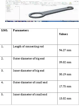
Connecting rod of Hero splendor, market available is selected for the present static load analysis . The dimensions of the selected connecting rod are found using vernier calipers, micro meter and are tabulated and presented in the Table 1. The material of Connecting rod is Cast Iron. According to the dimensions, the model of the connecting rod is developed using CREO. It is imported into design modeler of ANSYS 14.5. The modeled connecting rod is as shown in figure: 2. In this analysis four materials are used.
Material names:- C70S6 Steel, Structural Steel
S.NO. Parameters
Values
1. Length of connecting rod 94.27 mm
2. Outer diameter of big end 39.02 mm
3. Inner diameter of big end 30.19 mm
4. Outer diameter of small end 17.75 mm
[image:3.595.290.564.385.754.2]© 2017, IRJET | Impact Factor value: 5.181 | ISO 9001:2008 Certified Journal | Page 540 Model of connecting rod
Dimensions of connecting rod.
Orthographic view of specimen connecting rod for analysis
MATERIAL PROPERTIES
The properties of Structural Steel materials as shown in
Table Serial
No. Material properties Structural Steel 1 Young’s
modulus (E) 2.0×10⁵ MPa
2 Poisson’s
ratio (μ) 0.3
3 Density (ρ) 7.85×10⁻⁶ kg/mm3
4 Tensile ultimate strength
460 MPa
5 Tensile yield
strength 250 MPa
6 Compressive yield
strength
250 MPa
The properties of C70S6 Steel materials as shown in Table
S.NO. Material properties C70S6 Steel
1 Young’s modulus (E) 210×103 MPa
2 Poisson’s ratio (μ) 0.3
3 Density (ρ) 7.85×10⁻⁶
kg/mm3 4 Tensile yield strength 550 MPa
5 Compressive yield
strength 550 MPa
6 Tensile ultimate
strength 900 MPa
7 Compressive ultimate
strength 600 MPa
8 Fatigue strength 345 MPa
MESHING
The next stage of the modeling is to create meshing of the created model .The mesh model of connecting rod is as shown in figure: 4. Type of Element : Tetrahedron Number of Nodes : 22161 Number of Elements : 13733 Meshing size : 2 mm
Mesh model of connecting rod.
LOAD DIAGRAM OF CONNECTING ROD
© 2017, IRJET | Impact Factor value: 5.181 | ISO 9001:2008 Certified Journal | Page 541 load applied at the small end i.e. piston end of the
connecting rod and All degree of freedom are fixed for big end i.e. crank end of the connecting rod. It is shown in Figure
Load and boundary conditions of connecting rod.
RESULTS AND DISCUSSION
For the finite element analysis 677 N of load is used. The analysis is carried out using CREO and ANSYS work bench 14.5 software. The load is applied at the small end of connecting rod keeping big end fixed. The maximum and minimum von-misses stress, principal stress, elastic strain, and shear stress are noted from the ANSYS Work bench 14.5.
Material used for connecting rod is C70S6 Steel:-
Total Deformation of C70S6 Steel connecting rod.
the maximum total deformation occurs at the piston end of the connecting rod is 0.01271 mm and minimum total
deformation occurs at the crank end of the connecting rod is 0.00164 mm
the maximum equivalent elastic strain occurs at the piston end i.e. small end of the connecting rod is 1.960×10⁻⁴ and minimum equivalent elastic strain occurs at the crank end i.e. big end of the connecting rod is 4.218×10⁻⁶.
rod is Structural Steel:-
Total Deformation of Structural Steel connecting rod.
© 2017, IRJET | Impact Factor value: 5.181 | ISO 9001:2008 Certified Journal | Page 542 the maximum equivalent elastic strain occurs at the piston
end i.e. small end of the connecting rod is 2.059×10⁻⁴ and minimum equivalent elastic strain occurs at the crank end i.e. big end of the connecting rod is 4.429×10⁻⁶.
COMPARISON RESULTS
S.NO. Type C70S6 Steel Structural Steel
1 Total Deformation 0.01271 mm 0.01334 mm
2 Equivalent Elastic Strain 1.960×10⁻⁴ 2.059×10⁻⁴
3 Stiffness 50.74 kN/mm 53.26 kN/mm
Comparison Results
Name Maximum Minimum
Von-misses stress
41.117
MPa 9.194×10⁻² MPa
Principal
stress 26.826 MPa -1.997 MPa Shear
stress 21.594 MPa 4.999×10⁻² MPa
Static analysis of connecting rod.
CONCLUSION
Finite element analysis of the connecting rod of a Hero Splendor has been done using FEA tool ANSYS Workbench and are tabulated in Table 6 & Table 7.
1. Static analysis of materials is carried out by ANSYS
2. From the above table of static analysis, the stress induced by using ANSYS is less than the material allowable limit of stress. So the model presented here is well for safe design under given loading conditions.
3. Maximum stress occurs at the piston end of the connecting rod. Von-mises stress, principal stress and shear stress are same for C70S6 Steel and Structural Steel because of same load is applied.
4. Comparing the different results obtained from the analysis, it is concluded that the Deformation and Elastic Strain induced in the C70S6 Steel is less than the Cast Iron for the present investigation. Here C70S6 Steel can be used for production of connecting rod for long durability as cast iron is brittle material.
REFERENCES
[1] B. Anusha, Dr.C.Vijaya Bhaskar Reddy. Comparison of Materials for Two-Wheeler Connecting Rod Using Ansys. International Journal of Engineering Trends and Technology (IJETT) – Volume 4 Issue 9- Sep 2013.
[2] Bai-yan He, Guang-da Shi, Ji-bing Sun, Si-zhuan Chen, Rui Nie. Crack analysis on the toothed mating surfaces of a diesel engine connecting rod. Engineering Failure Analysis 34 (2013) 443–450.
[3] Bin Zheng, Yongqi Liu and Ruixiang Liu. Stress and Fatigue of Connecting Rod in Light Vehicle Engine. The Open Mechanical Engineering Journal, 2013, 7, 14-17.
© 2017, IRJET | Impact Factor value: 5.181 | ISO 9001:2008 Certified Journal | Page 543