© 2017, IRJET | Impact Factor value: 5.181 | ISO 9001:2008 Certified Journal | Page 178
SPEED CONTROL AND SYNCHRONIZATION OF DC MOTORS USING
WIRELESS MODULE
Asifa Parvaiz
1, Mitali Sadhwani
2, Ashwini Bidker
2, Krunal Dheple
2, Jitendra Kawadkar
2, Amol
Bhoyar
21Asst, Prof, Department of Electrical Engineering, S.B.J.I.T.M.R, Nagpur, [email protected]. 2 Students, Department of Electrical Engineering, S.B.J.I.T.M.R, Nagpur
---***---Abstract
— The main objective of the project is to
control the speed and synchronization of DC
motors using wireless module with higher
efficiency and less maintenance. The speed control
and synchronization of motors is an essential part
of any industries, therefore it is an at most need to
solve this problem. Multiple motors are working
on load in an industry with one motor act as
master and remaining two motor acting as slave,
so synchronization becomes necessary. In this
paper, the DC motors are used for synchronization
because of their smooth operation, less noise &
low torque. PWM technique used in our project to
control the speed. Synchronization have been
done through USART device using wireless module
(WIR-1186v2).
Keywords
—
DCmotor,PIC18F4520,
PWM
technique, Driver circuit, Wireless module,
LCD, etc.
1.INTRODUCTION
Traditionally conveyor belts, line shaft, pullers are used in order to synchronize multiple motor for doing particular works. But these techniques have many drawbacks such as the master slave [main motor] will be the hardest to start, stop and maintain smooth motion on the whole process. Maintenance is bit difficult as there are more mechanical parts in the system. This can be come over by using the wireless synchronization of multiple motors [1]. This project is designed to overcome all these problems. In this project, wireless technology is used to synchronize the motors without any differential error speed. Among all the motors one motor acts as transmitter
and all other motor as receivers, therefore the speed set in the transmitter side of the motor, the same speed will be applied to all the receivers side of the motors [3]. This operation can be possible by using universal asynchronous receiver transmitter (UART) device. Generally the loads applied on the motors is variable, due to that the speed of the motor will affect and satisfactory operation will not achieve. For minimizing that problems, the speed control is necessary. PWM technique is used for controlling the speed of the motors [9]. For PWM generation PIC18F4520 is used. In this method, the regulation of motor’s speed is achieved by changing the voltage of the motor which is adjusted by the duty cycle of PWM. Instead of using transformer and rectifier for giving supply, we used Adapter to give 12V supply to the DC motor. IC7805 is used to convert 12V into 5V supply. 12V DC motor is used for speed control and synchronization purpose. Driver circuit consists of BJT, MOSFET for interfacing between DC motor and PIC, because direct dc motor can’t connect to the PIC. Manpower and time is saved in this arrangement. Satisfactory operation will obtain
1
.
1 Speed Control And Synchronizationa. Initially, the 220v AC supply is fed to the adapter which converts 220 into 12v supply. After this 12v supply is given to the positive terminal of 12v dc motor. By using regulator IC7805, 12V is converted into fixed 5V DC supply and it is given to the PIC18F4520.
© 2017, IRJET | Impact Factor value: 5.181 | ISO 9001:2008 Certified Journal | Page 179 d. PWM pulses are generated from PIC according to
the required speed, the main or master motor is adjusted to that speed and transfer that particular speed through wireless module of transmitter to receiver and maintain that speed at slave motor.
e. Another two sets of receiver side of DC motors are run at that speed which run at the transmitter side. The speed at which the DC motor is running is show on the LCD display. This LCD is interfaced with PIC.
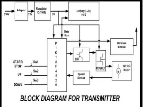
Fig 1. Block Diagram of Transmitter
The block diagram of transmitter and the receiver set of DC motors are shown above. The entire arrangement consists of a single transmitter circuit and two receiver circuits.
The block diagram of the receiver side which is exactly same as the transmitter block diagram the only difference is that the arrangement of switches is not present in the receiver side because the slave motors will going to operate at the speed which is set by the master motor and is done by the switches as we have discussed above. Thus, the switches are replaced by wireless module.
[image:2.595.310.556.98.262.2]These block diagram consists of main parts such as power supply, PIC18F4520, LCD, DC motor, wireless module, driver circuit.
Fig 2. Block Diagram of Receiver
1.2 Wireless Module (Wir-1186)
Wireless communication, or sometimes simply wireless, is the transfer of information or power between two or more points that are not connected by an electrical conductor. The most common wireless technologies use radio waves. An RF module (radio frequency module) is a (usually) small electronic device used to transmit and/or receive radio signals between two devices. This wireless communication may be accomplished through radio frequency (RF) communication. The WIR-1186 module is a low-power wireless communication solution that is ideal for Smart Grid, home automation, smart lighting, industrial sensor data acquisition and remote control applications. This module supports simple point-to-multipoint serial communication over-the-air. It has a small 24mm x 36mm form-factor for easy integration. OTA Range is 1km to 2km.This module has total 6 pins (GND VCC, TX, RX, PROG, CTS).
Pin no. 1 - GND
Pin no. 2 - VCC (supply voltage- 3.2V – 3.6V supply voltage)
Pin no. 3 -PROG Enter configure mode (active-low) Pin no. 4 -UART-TX Module Serial Data input Pin no. 5 -UART-RX Module Serial Data output Pin no. 6 - CTS Clear to send output to device
1.3. Driver Circuit
[image:2.595.37.291.228.416.2]© 2017, IRJET | Impact Factor value: 5.181 | ISO 9001:2008 Certified Journal | Page 180 be used to control the movement of DC motors
directly by using pulse-width modulation (PWM) type controllers. As a DC motor offers high starting torque and which is also proportional to the armature current, MOSFET switches along with a PWM can be used as a very good speed controller that would provide smooth and quiet motor operation. NPN type BJT is used here which is made from silicon semiconductor material. If the transistor’s base emitter is open (Ib=0) the device is in off state.
1.4. Pluse Width Modulator (Pwm)
Pulse-width modulation (PWM) or duty-cycle variation methods are commonly used in speed control of DC motors. The duty cycle is defined as the percentage of digital ‘high’ to digital ‘low’ plus digital ‘high’ pulse-width during a PWM period. The average DC voltage value for 0% duty cycle is zero; with 25% duty cycle the average value is 1.25V (25% of 5V). With 50% duty cycle the average value is 2.5V, and if the duty cycle is 75%, the average voltage is 3.75V and so on. The maximum duty cycle can be 100%, which is equivalent to a DC waveform. Thus by varying the pulse-width, we can vary the average voltage across a DC motor and hence its speed.
1.5 Universal Asynchronus Receiver/ Transmitter (Uart)
[image:3.595.310.533.138.483.2]The Universal Synchronous Asynchronous Receiver Transmitter (UART) module is one of the two serial I/O modules (Generically, the UART is also known as a Serial Communications Interface or SCI). The pins of the Enhanced USART are multiplexed with PORTC. The speed of communication (measured in bauds) is predetermined on both ends. Baud Rate: No. of bits transmitted/received per second bits/sec. A general rule of thumb is to use 9600 bauds for wired communication. Parity bit is HIGH when number of 1’s in the Data is odd. Respectively, it is LOW when number of 1’s in the Data is even.
Fig 3. Block Diagram of Transmitter
2. Working Principle
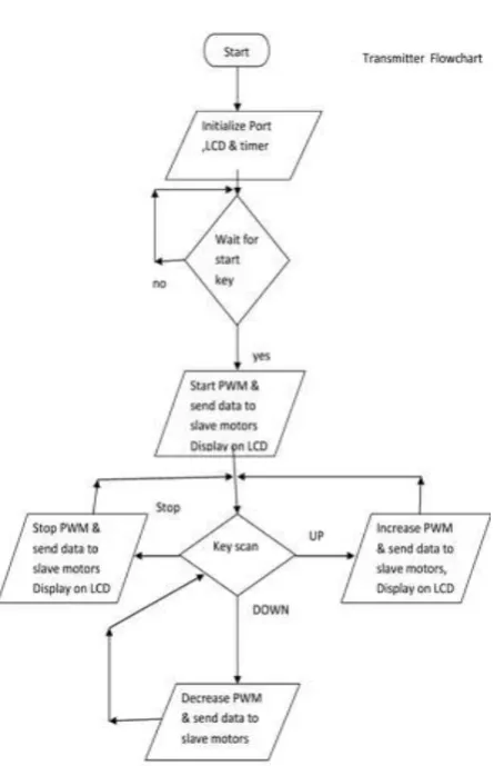
[image:3.595.48.280.655.747.2]2.1 Transmitter Flowchart
Fig 5. Flow Chart of Transmitter
Step-1: Switch on the supply to start the DC motor.
• There are two conditions: No or Yes.
• If the command given is No, then the program will standstill at step 2.
• If the command given is Yes, then controller will start the PWM and will send data to slave motors and display on LCD.
Step-2: This will initialize the port, LCD and timer. Step-3: Now the controller will wait for the command on the start key.
Step-4: At this step, there are three input options namely, UP (Increase speed), DOWN (Decrease speed) and STOP. Then the controller will scan the input key pressed.
© 2017, IRJET | Impact Factor value: 5.181 | ISO 9001:2008 Certified Journal | Page 181 • If the input is DOWN, the controller will decrease
PWM, send data to slave motors and display on LCD. • If the input is STOP, the controller will stop PWM, send data to slave motors and display on LCD.
[image:4.595.37.290.189.372.2]Step-5: According to the input given, the master motor will operate.
Fig 6. Hardware model of Transmitter
2.2 Receiver Flowchart
.
Step-1: Switch on the supply to start the DC motor. Step-2: This will initialize the port, LCD and timer. Step-3: Now the controller will wait for the command on the start key.
• There are two conditions: No or Yes.
• If the command given is No, then the program will standstill at step 2.
• If the command given is Yes, then controller will start the PWM and will send data to slave motors and display on LCD.
• Again at this step, there are three input options namely, UP(Increase speed), DOWN(Decrease speed) and STOP. Then the controller will scan the input key pressed.
Step-4: The wireless module of the receiver will read the wireless data.
• If the input is UP, the controller will increase PWM, send data to slave motors and display on LCD.
• If the input is DOWN, the controller will decrease PWM, send data to slave motors and display on LCD.
[image:4.595.309.563.437.589.2]Step-5: According to the input received by wireless module, the slave motors will operate.
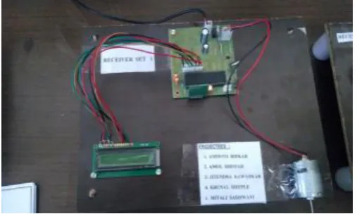
Fig 8. Hardware Model of Receiver
3. Results
The following hardware and software are required for implement the design and to control the speed and synchronize dc motor using wireless module. • • Proteus 8 Professional
• • Mikro C Pro for PIC
© 2017, IRJET | Impact Factor value: 5.181 | ISO 9001:2008 Certified Journal | Page 182
3.1 Proteus 8 Professional Software
Proteus software provides an interactive platform to simulate devices ranging from small transistor to microcontrollers and even serial port communication. Basically PROTEUS is also a simulating software but it helps you attach many components with the PIC. Like resistors, capacitors, LEDs, LCDs, keypads, ICs etc. It has a complete library and you will find everything that you will ever need. You can design your complete circuit and then simulate it to view the final output.
This means that after perfecting your project on the programming side in MICRO C FOR PIC, you'll need to simulate it on PROTEUS to determine the output of the hardware components and change it if need be. This will completely ensure your project's success. Here are the basic steps:
• Place your components from the library • Connect them accordingly
• Load HEX file (if PIC is involved
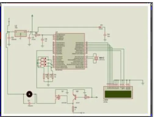
Fig 9. Circuit Diagram of Transmitter Set
The Mikro C PRO for PIC is a powerful, feature-rich development tool for PIC microcontrollers. Mikro C is the easier programming software that I ever learn compared to other programming software. It very suitable for students to learn and create embedded system. Mikro C support some PIC microcontroller that created by Microchip company. Once you have created the project and written the source code, it's time to compile it. Chose one of the build options from the Project menu:
To create a HEX file select Build from the Project menu or click the Build Icon from the Project Toolbar. The Build ALL option builds all files from
the project, library(if there is a source code) and def files for chip in use.
The Build + Program option is very useful. After the code is compiled Mikro C will load .hex file in the PIC Flash programmer used to program your microcontroller. If there are errors, you will be notified in the Message Window. If no errors are encountered, the MikroC for PIC will generate output files.
In Proteus, you can load an "assembly code" to micro-controller and compile it and then can run the simulation. Go and do it
• The speed control and synchronization of DC motors using wireless module have been successfully done. The amount of speed which is set in the transmitter set of main (master) motor, the same speed rang is obtained in the receiver set of the slave motor using wireless module.
Below table shows the speed range of DC motor between transmitter and receiver sets. The desired result has been obtain from PWM and UART techniques
Table 6.1: Observation Obtain from Speed synchronization of DC motors.
Master Motor Slave
Motor-1 Slave Motor-2
Speed %
Time
delay Speed % delay Time Speed % delay Time
15% 200ms 15% 200ms 15% 200ms
45% 200ms 45% 200ms 45% 200ms
75% 200ms 75% 200ms 75% 200ms
The DC motor’s speed is operated in the range between 10% to 100%. If we take duty cycle 50%, then the LCD speed of the motor in terms of % i.e. 50%.
[image:5.595.38.291.380.572.2]© 2017, IRJET | Impact Factor value: 5.181 | ISO 9001:2008 Certified Journal | Page 183 From the above shows the speed synchronization
of DC motor, the speed is same for transmitter and receiver section. Desired result is obtained Also, Interfacing of LCD, wireless module, DC
motor have been successfully done.
The programming of transmitter and receiver side section also done successfully
4. CONCLUSIONS
The designing of a sustainable system to control the speed and the synchronization of DC Motor using wireless module have been successfully implemented in this paper. DC motors have speed control capabilities which means that speed, torque and even direction of rotation can be changed at anytime to meet new condition. The speed control have successfully done using PWM techniques. The synchronization of three sets of DC motor have been easily done using UART device. This project provides a platform for further advancement in the field of industrial use of motors. DC motors of all range can be controlled, which are used for the production of materials Electric locomotives DC motor using precise job preparations
REFERENCES
[1] Gopal K. Dubey, “Fundamentals of Electric Drives” Narosa Publishing House New Delhi,1989 [2] Dr. Steve C. Hsiung. “The Use of PIC Microcontrollers in Multiple DC Motors Control Applications “
[3] Pratiksha Shingade, Arati Dalavi, Priyanka Shipate, Megha Barge “Wireless Digital Control and Synchronization of Master-Slave Multiple Motors Using Microcontroller”
[4] Ganiyu, R. A., Shoewu, Olatinwo, S. O., Omitola, O. O. “Development of a Micro controller Based Motor Speed Control System Using Intel 8051”. [5] J.M. Bourgeois SGS-THOMSON “A New Isolated
Gate and Base Drive for Power MOSFETs and IGBTs, Microelectronics application note AN461”. [6] Aminurrashid Noordin, Moohd Hanif Che Hasan, Sulaiman Sabikan, Mohd Razali Muhamad Sapiee “Proteus professional design”
[7] Mangesh J Nemade, Akhileshkumar K Singh, Payal Satao "Closed Loop Speed Control of Dc Motor Using Pwm", Electrical, PLITMS, India [8] Muhammad H. Rashid, “Power Electronics”,
Prentice Hall International Inc., New Jersey, 1996.
[9] UART pdf by RUDRA PRATAP SUMAN, http://www.tetraedre.com/ advanced / serial / index.html.
Mrs.Asifa Parvaiz
Asst.Professor. Department of Electrical Engineering
S.B. Jain Institute of Technology Management and Research, Nagpur
Ku. ASHWINI V. BIDKAR
B.E. Final Year Electrical Engineer. Student, Studied at S.B. Jain Institute of Technology Management and Research, Nagpur
Ku. MITALI SADHWANI
B.E. Final Year Electrical Engineer. Student, Studied at S.B. Jain Institute of Technology Management and Research, Nagpur
JITENDRA KAWADKAR
B.E. Final Year Electrical Engineer. Student, Studied at S.B. Jain Institute of Technology Management and Research, Nagpur
KUNAL DHEPLE
B.E. Final Year Electrical Engineer. Student, Studied at S.B. Jain Institute of Technology Management and Research, Nagpur
AMOL BHOYAR