Modified Model Reference Adaptive Control for the Stabilization of Cart
Inverted Pendulum System
Arya V A
1, Aswin R B
2, Ashni Elisa George
31Mtech Scholar, Dept. of EEE, Mar Baselios College of Engineering and Technology, Nalanchira, Kerala, India 2,3 Assistant Professor, Dept. of EEE, Mar Baselios College of Engineering and Technology, Nalanchira, Kerala, India
---***---Abstract -
Control of Inverted Pendulum (IP) is a classicalexperiment done in laboratories. It is found in various control system applications like robotic arm, satellite launching system etc. A Pendulum is a weight suspended from a pivot with its Centre of gravity acting below the pivot. It will come back to equilibrium position if it is displaced sideways. On the other hand, an IP has Centre of gravity acting above its axis of rotation. Hence it is an unstable system. Cart Inverted Pendulum (CIP) system is considered here. The basic control objective is to maintain the unstable equilibrium position, by controlling the force applied in the horizontal direction to the mobile cart. The control is challenging as CIP is highly unstable, non-linear and under actuated system. The cart and pendulum is controlled separately. The pendulum is controlled by a Proportional–Integral–Derivative (PID) controller and the cart is controlled using Model Reference Adaptive Control (MRAC) using Lyapunov’s Stability Theory. There is only one control action allowed for CIP so the control actions of pendulum and cart are to be combined into one control force. The stabilization of CIP has been done using MRAC by tracking the cart position. The results are obtained in
MATLAB/Simulink environment.
Key Words: Inverted Pendulum, Cart, Pendulum, PID
controller, MRAC, Lyapunov’s Stability theory
1. INTRODUCTION
By the time of launching a rocket or space craft, the main difficulty is to maintain the rocket in the upright position against gravity and keep it on a pre-specified trajectory by overcoming all external disturbances and internal non-linearity present with the system. The risk behind these balancing problems can be studied with the help of CIP models. The CIP system consists of an inverted pendulum mounted on the top of a mobile cart [1]. The pendulum is unstable without control and will simply fall off if the cart is not moved.
The pendulum can be balanced by applying a force to the cart, to which the pendulum is attached. The cart is constrained to move only in the horizontal x direction, while the pendulum can only rotate in the x-y plane. The objective is to balance the pendulum in upright position by controlling the force applied to the cart. Two controllers are used each for cart and pendulum subsystems [2].
MRAC is a tracking control so it is implemented in cart
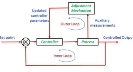
control technique. It consists of a referece model . It has two loops. The inner loop is the regular feedback loop consisting of the controller and the process and the outer loop is composed of a adaptation mechanism that changes the controller parameters. The process and model outputs are compared and the error function is minimized [3].
The PID controller is used to control the pendulum subsystem. This controller algorithm involves three separate parameters [4]. The proportional, integral and derivative values, denoted P, I and D. PID controllers will yield better transient and steady state responses, if the system parameters remain unchanged. PID controller is used for controlling the pendulum subsystem.
The control action for the pendulum subsystem and cart subsystem are to be combined into one control action. This control action is provided to stabilize the CIP system. Various other controllers can be studied and tested using this system like Sliding Mode Control [5], Adaptive Fuzzy control [6], Linear Quadratic Control [7] etc. Hence it has got much importance in control system field.
2. MODELLING OF CIP
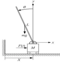
The Inverted pendulum mounted on top of a motor driven cart is shown in figure 1. The aim is to keep the pendulum at its vertical position. The pendulum at inverted position is unstable and it may fall off due to gravity so a control force must be applied to the cart.
[image:1.595.385.491.651.762.2]Where
Ѳ– Angle of Pendulum F – Force applied to the Cart m - Mass of the Pendulum M – Mass of the Cart
L – Length of the pendulum rod
l – Length between the pivot and centre of gravity I – Inertia of Pendulum
x – Cart position
g – Acceleration due to gravity
The nonlinear equations of motion are
(1)
(2)
Let (3)
(4)
(5)
Equations (1) & (2) change to (6)
(7)
After linearization by small angle approximation Sin = ; cos = 1 ; = 0 (8)
sub in (6) & (7) ; we get (9)
(10)
Taking Laplace Transform of (9) & (10) (11)
(12)
From the above equation (13)
sub (13) in (11) (14)
[image:2.595.286.559.260.393.2](15)
Table -1: Modeling Parameters Mass of cart, M 2 Kg Mass of Pendulum, m 0.2 Kg Length of pendulum from pivot to the Centre of mass 0.5 m Acceleration due to gravity 9.81 m/ A gain of 15 units is provided to the plant for the conversion of control signal to control force instead of the DC motor. (16)
(17)
The equations (16) and (17) represent the Cart and Pendulum Transfer functions. Two separate controllers are designed for each and then combined to get a total control force and is provided to the CIP system.
3. CONTROL FRAMEWORK
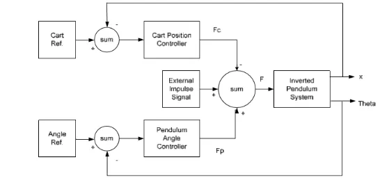
Controllers stabilize the unstable system and make it robust to disturbances. Here conventional PID controller and MRAC has been implemented for CIP system. The framework of CIP controller system is presented in figure 2.
Fig - 2: Block diagram of CIP controller system
The CIP has two separate controllers, pendulum angle controller and cart position controller. However, there is only one control action allowed for the CIP system. Therefore, the control action, Fp for the pendulum subsystem and Fc for the cart subsystem need to be combined into one control action F. When a control action is provided to push the cart to left side will cause the pendulum to move to the right side. This knowledge indicates that the control actions to move the pendulum and cart to the same direction should have opposite sign. The cart position is controlled by MRAC using Lyapunov’s theory and the pendulum angle is controlled by PID controller.
3.1Model Reference Adaptive Control
Fig - 3: Block diagram of MRAC
The controller parameters in MRAC are adjusted by Lyapunov’s stability theory. Consider a linear system which is asymptotically stable
(18)
Then for each symmetric positive definite matrix Q, there exists a unique symmetric positive definite matrix P such that
(19)
If there exist a function
(20)
Then V(x) is a Lyapunov’s function
The general strategy while designing MRAC for linear system using state space include the selection of the control law then an error equation is derived. A proper Lyapunov’s function is chosen to determine the adaptive laws hence the error can be minimised.
The reference model output is , is the plant output, e is the error output, u is the control input, r is the reference input, is the adaptive gain, is the damping ratio, is the natural frequency.
The state space equation for reference model of the Cart is
(21)
where ; ;
The state space equation for Cart can be represented as
(22)
The control law is chosen as
(23) sub (23) in (22)
(24) where,
; ;
The differential equation for error is
(25) where,
A positive definite function is formed from above eqns as
(26) The derivative of V
(27)
is negative definite, hence V is Lyapunov’s function. The adaptive laws are chosen to be:
(28)
(29) Then by Lyapunov’s theory
(30)
Solving (30) by substituting
We get matrix P
(31)
By solving the Adaptation laws. The controller parameters are obtained as
(33)
(34)
(35)
where, & are elements of matrix P, , , are the adaptive gains and , , are the controller parameters.
MRAC for cart is designed by selecting a second order differential equation as the reference model.
(36)
where, is the reference model transfer function. To obtain a critically damped response with and .
3.2PID Control
process control applications. The different characteristic features: it provides feedback; it has the ability to eliminate steady-state offsets through integral action; and it can anticipate the future through derivative action.
Fig - 4: PID Block diagram
PID controller has the optimum control dynamics such as zero steady state error, short rise time, no oscillations and higher stability. The derivative gain component is added to the PI controller to eliminate the overshoot and the oscillations occurring in the output response of the system. One of the main advantages is that it can be used with higher order processes with more than single energy storage.
As the plant model is open loop unstable Ziegler Nichols tuning method cannot be used. Therefore, PID controller for pendulum is designed by selecting a desired pole by choosing desired specifications for damping ratio ( ), natural frequency ( ) and steady state error (ess).
(37)
(38)
(39) where, and
and
, and are the proportional, integral and derivative gain. is velocity error constant
4. SIMULATION RESULTS
The MRAC for Cart subsystem is designed by considering the reference model to be
(40)
[image:4.595.34.289.145.247.2]The Adaptive gains are chosen to be -1 and +1. The PID gains for the pendulum subsystem are designed as , , . The MRAC designed for Cart and PID control designed for the Pendulum subsystems are combined and provided to the CIP system for stabilisation. The Simulink block diagram is shown in Fig - 5.
Fig - 5: Simulink Block diagram for the control of CIP
[image:4.595.324.568.332.469.2]The reference position for Cart is chosen to be 1m. The figure 6 shows the MRAC outputs for Cart. The first graph show the variation of reference position and reference model output with time. The second graph shows the variation of reference model output and Cart output with time.
Fig - 6: MRAC outputs for the Cart system
[image:4.595.323.567.566.701.2]The variation of the Cart position with time is shown in Fig - 7.The designed MRAC gains are provided to the Cart subsystem. The Cart output tracks the reference model output with in 15s.
Fig - 7: Simulation result for the Cart position Control
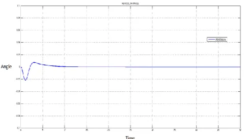
The figure 8 shows the variation of pendulum angle with time. The pendulum settles at the reference angle with in 10s.
Fig - 8: Simulation result for the Cart position Control
3. CONCLUSIONS
A good tracking is obtained for Cart position with MRAC using Lyapunov’s theoy. PID control and MRAC are designed and simulated in MATLAB/Simulink environment. Stabilisation of the Pendulum at its upright position is obtained with the combined control. The simulation results suggest that better response is obtained with the combination of MRAC and PID control for Cart position tracking and Pendulum angle respectively. In future MRAC using Stability Augmentation can be implemented for Cart position tracking.
REFERENCES
[1] C. W. Tao, Jinshiuh S. Thaur, Tzuen Wuu Hsieh, “Design of a Fuzzy Controller with Fuzzy Swing-up and Parallel Distributed Pole Assignment Schemes for an Inverted Pendulum and Cart System”, IEEE Transactions on Control Systems Technology, vol. 16, no. 6, Nov. 2008.
[2] A. Ghosh, T. R. Krishnan, B. Subudhi “Robust Proportional-IntegraDerivative compensation of an Inverted-Cart Pendulum System” IET Transactions on Control Theory and Applications, vol. 6, no. 8, pp. 1145-1152, Sept. 2012.
[3] Daniel E. Miller, Naghmeh Mansouri, “Model Reference Adaptive Control Using Simultaneous Probing, Estimation, and Control” , IEEE Transactions On Automatic Control, Vol. 55, no. 9, Sept 2010.
[4] Sandeep D. Hanveeth, Yogesh V. Hote, “Design of PID controller for Inverted Pendulum using Stability Boundary Locus”, IEEE Conference on Control theory, pp. 380–387, 2014.
[5] Mun-Soo Park, Dongkyoung Chwa, "Orbital Stabilization of Inverted-Pendulum Systems via Coupled Sliding-Mode Control," IEEE Transactions on
Industrial Electronics , vo1.56, no.9, pp.3541-3555, Sept. 2009.
[6] Mohamed I. El-Hawwary, A. L. Elshafei, H. M. Emara and H. A. Abdel Fattah, “ Adaptive Fuzzy Control of the Inverted Pendulum Problem” IEEE Transactions on Control System Technology., vol. no. 6’pp.1135-1144, Nov. 2012.
[7] Nenad Muskinja , Boris Tovornik , “Swinging Up and Stabilization of a Real Inverted Pendulum”, IEEE Transactions on Industrial Electronics, vol. 53, no. 2, April 2006.
[8] Kuo-Kai Shyu, Ming-Ji Yang, Yen-Mo Chen, and Yi-Fei Lin on IEEE transaction titled “Model Reference Adaptive Control Design for a Shunt ActivePower-Filter System” , IEEE Transactions on Industrial Electronics , vo1.55, no.1, pp. 97 - 105 , Jan. 2008.
[9] Marido di Bernardo, Umberto Montanaro, Stephania Santini, “Hybrid Model Reference Adaptive Control System of Piecewise affine system, IEEE transactions on automatic control Vol.58, No.2 Feb 2013.

![Bromido[(1,2,5,6 η) cycloocta 1,5 diene]methylplatinum(II)](data:image/gif;base64,R0lGODlhAQABAIAAAP///wAAACH5BAEAAAAALAAAAAABAAEAAAICRAEAOw==)