© 2018, IRJET | Impact Factor value: 6.171 | ISO 9001:2008 Certified Journal | Page 320
DOOR ACCESS SECURITY SYSTEM USING NFC TECHNOLOGY
Idrish Shaik
1, Sesh Karthik Chilukuri
2, Bobburi Tejaswi
31
Assistant Professor, Dept. of ECE, Bapatla Engineering College, Bapatla, Andhra Pradesh, INDIA
2, 3Student, Dept. of ECE, Bapatla Engineering College, Bapatla, Andhra Pradesh, INDIA
---***---Abstract -
This project focuses on developing a Near FieldCommunication (NFC) Smart Lock System that utilizes a smart phone’s on-board NFC chip as a method to unlock a door. Access is regulated using a NFC Smart Card which runs a simple user interface that allows an Administrator to grant or deny entry to any particular user. The goal for this project was to give access to particular user. Access will be given to the user by using NFC Smart Card. Every NFC Smart Card contain Unique Identification (UID) Number, by using UID we grant or deny entry to user. It is working on NFC door lock that will be available to the general public at an affordable price. The goal of this project is to create a more convenient way to unlock your door than the traditional key. In the key’s place is an NFC tag that will unlock the door by proximity. However, the improvements of this NFC door lock must outweigh the complications of implementation. The list of customer needs (in the Requirements and Specifications section) was constructed with that fundamental goal in mind. The design consists of two components. The first component is the actual door lock that must be installed in the door frame. This will be controlled by a magnetic lock and will need to be powered. The second component is a relatively small module that you can install anywhere near the door. This module is responsible for the NFC sensing.
Key Words: Unique Identification (UID), Near Field Communication (NFC) Technology, Smart card or NFC TAG, Arduino UNO, Smart lock or Solenoid Electric Door Lock.
1. INTRODUCTION
Near Field Communication (NFC) is a technology for contactless short-range communication. Based on the Radio Frequency Identification (NFC), it uses magnetic field induction to enable communication between electronic devices. The number of short-range applications for NFC technology is growing continuously, appearing in all areas of life. Especially the use in conjunction with mobile phones offers great opportunities.
One of the main goals of NFC technology has been to make the benefits of short-range contactless communications available to consumers globally. The existing radio frequency (RF) technology base has so far been driven by various business needs, such as logistics and item tracking. While the technology behind NFC is found in existing applications, there has been a shift in focus most notably, in how the technology is used and what it offers to consumers.
With just a point or a touch, NFC enables effortless use of the devices and gadgets we use daily. Here are some examples of what a user can do with an NFC mobile phone in an NFC-enabled environment:
Download music or video from a smart poster. Exchange business cards with another phone. Pay bus or train fare.
Print an image on a printer. Pair two Bluetooth devices.
Use a point-of-sale terminal to pay for a purchase, the same way as with a standard contactless credit card.
An NFC-enabled phone functions much like standard contactless smart cards that are used worldwide in credit cards and in tickets for public transit systems. Once an application, such as a credit card application, has been securely provisioned to the NFC-enabled phone, the customer can pay by simply waving the phone at a Point-of-sale reader. The NFC phone also offers enhanced security, enabling the user to protect the secure applications through the phone's user interface features. NFC operates in the standard, globally available 13.56MHz frequency band. Possible supported data transfer rates are 106, 212 and 424 kbps and there is potential for higher data rates. The technology has been designed for communications up to a distance of 20 cm, but typically it is used within less than 10 cm. This short range is not a disadvantage, since it aggravates eavesdropping.
1.1 DEVELOPMENT OF NFC TECHNOLOGY
© 2018, IRJET | Impact Factor value: 6.171 | ISO 9001:2008 Certified Journal | Page 321 In an NFC communication, two devices are needed.
[image:2.595.66.270.186.288.2]First device is called the initiator which is an active device and is responsible for starting the communication, whereas second device is called the target and responds to the initiator’s requests. The target device may be active or passive. The communication starts when the active device gets close to the target and generates a 13.56 MHz magnetic field and powers the target device (See Figure 1.1).
Fig -1.1: NFC Enabled Phone
1.1.1 TAG
[image:2.595.330.537.225.327.2]The tag is a thin simple device containing antenna and small amount of memory. It is a passive device, powered by magnetic field. Depending on the tag type the memory can be read only, re-writable, and writable once (See Figure 1.2).
Fig -1.2: NFC TAG
1.1.2 READER
The reader is an active device, which generates radio signals to communicate with the tags. The reader powers the passive device in case of passive mode of communication (See Figure 1.3).
Fig -1.3: NFC enabled phone
1.2 NFC MODULE (PN532)
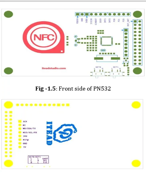
TEAD PN532 NFC module (See Figure 1.4), as its name implies, is based on PN532 chip and used for 13.56MHz near field communication. The module is equipped with onboard antenna, thus no external antenna coil is needed. It is compatible with SPI, IIC and UART interface for communication. With NFC library support for Arduino and Raspberry Pi offered by us, it is quite convenient for development of products with NFC functions.
Fig -1.4: NFC Module
Features
Longest effective communication distance of 3 cm.
Supports switching of SPI, IIC and UART interface.
Can be used for 13.56M non-contactcommunication.
Compatible with ISO14443 Type A and Type Bstandards.
Table -1: Specifications
IC NXP PN532
Operating Voltage 3.3V
Power Supply Voltage 3.3~5.5V
Max Supply Current 150mA
Working Current(Standby
Mode) 100mA
Working Current(Write
Mode) 120mA
Working Current(Read
Mode) 120mA
Indicator PWR
Interface SPI Interface, Std.
[image:2.595.48.255.409.521.2]© 2018, IRJET | Impact Factor value: 6.171 | ISO 9001:2008 Certified Journal | Page 322 Fig -1.5: Front side of PN532
[image:3.595.83.226.415.480.2]Fig -1.6: Back side of PN532
Table -2: There are two slide switches on the board for selection of interface mode
UART
:
Pronounced u-art, and short for universal asynchronous receiver-transmitter, the UART is a computer
component that handles asynchronous serial
communication. Every computer contains a UART to manage the serial ports, and some internal modems have their own UART.
A UART usually contains the following components:
A clock generator, usually a multiple of the bit rateto allow sampling in the middle of a bit period.
Input and output shift registers.
Transmit/receive control.
Read/Write control logic.
Transmit/Receive buffers (optional).
System data bus buffer (optional).
First-in, first-out (FIFO) buffer memory (optional).
Signals needed by a third party DMA controller(optional).
Integrated bus mastering DMA controller (optional).I2C Bus (Inter-IC Bus):
The I2C (Inter-IC) bus is a bi-directional two-wire serial bus that provides a communication link between integrated circuits (ICs). Phillips introduced the I2C bus 20 years ago for mass-produced items such as televisions, VCRs, and audio equipment. Today, I2C is the de-facto solution for embedded applications. There are three data transfer speeds for the I2C bus: standard, fast-mode, and high-speed mode. Standard is 100 Kbps. Fast-mode is 400 Kbps, and high-speed mode supports high-speeds up to 3.4 Mbps. All are backward compatible. The I2C bus supports 7-bit and 10-bit address space devices and devices that operate under different voltages.
SPI (Serial Peripheral Interface):
In a computer, a serial peripheral interface (SPI) is an interface that enables the serial (one bit at a time) exchange of data between two devices, one called a master and the other called a slave. An SPI operates in full duplex mode.
Fig -1.7: Serial Peripheral Interface
1.3 SOLENOID ELECTRIC DOOR LOCK
Fig -1.8: SOLENOID ELECTRIC DOOR LOCK
Solenoids are basically electromagnets: they are made of a big coil of copper wire with an armature (a slug of metal) in the middle. When the coil is energized, the slug is pulled into the center of the coil. This makes the solenoid able to pull from one end.
SET0 SET1
UART L L
SPI L H
© 2018, IRJET | Impact Factor value: 6.171 | ISO 9001:2008 Certified Journal | Page 323 This solenoid in particular is nice and strong, and
has a slug with a slanted cut and a good mounting bracket. It's basically an electronic lock, designed for a basic cabinet or safe or door. Normally the lock is active so you can't open the door because the solenoid slug is in the way. It does not use any power in this state. When 9-12VDC is applied, the slug pulls in so it doesn't stick out anymore and the door can be opened.
The solenoids come with the slanted slug as shown above, but you can open it with the two Phillips-head screws and turn it around so its rotated 90, 180 or 270 degrees so that it matches the door you want to use it with.
To drive a solenoid you will a power transistor and a diode, check this diagram for how to wire it to an Arduino or other microcontroller. You will need a fairly good power supply to drive a solenoid, as a lot of current will rush into the solenoid to charge up the electro-magnet, about 500mA, so don't try to power it
with a 9V battery.
2. WORKING
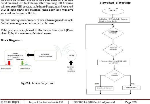
Arduino EEPROM contain a program to read UID from NFC tag by using NFC Module. And program contain a UID to compare with received UID, it is used to give an access to required user.
NFC Module receive UID from NFC Tag. Then NFC Module Send received UID to Arduino, after receiving UID Arduino will compare UID present in Arduino Program and received UID. If both UID’s are matched, then door lock will give access if not buzzer will ON.
By this technique we can secure more than regular door lock. So that we can give access to particular user.
Total process is explained in the below flow chart (Flow chart 1) by this we can understand more.
[image:4.595.308.557.85.187.2]Block Diagram:
[image:4.595.33.554.436.797.2]Fig -2.1: Access Deny User
Fig -2.2: Access Granted User
Arduino EEPROM contain a program to read UID from NFC tag by using NFC Module. And program contain a UID to compare with received UID, it is used to give an access to required user.
NFC Module receive UID from NFC Tag. Then NFC Module Send received UID to Arduino, after receiving UID Arduino will compare UID present in Arduino Program and received UID. If both UID’s are matched, then door lock will give access if not buzzer will ON.
By this technique we can secure more than regular door lock. So that we can give access to particular user.
Total process is explained in the below flow chart (Flow chart 1) by this we can understand more.
© 2018, IRJET | Impact Factor value: 6.171 | ISO 9001:2008 Certified Journal | Page 324 Advantage
NFC door lock is does not require to carry a key with you.
You can provide entry for others with your discretion.
Easy to use.
Tag does not require power supply. Highly secured.
3. CONCLUSIONS
This project concludes, allow only access granted user and stop the access deny user. It works based on Door Security using NFC Technology. By using NFC tags, we control the access to user.
NFC based security and access control system is more secure and fast responded as compared to the other system like biometric. The advantage of the NFC system is contact-less and works without-line-of-sight. By using Arduino it is easy to access and works very quickly while burning the code it is like plug and play device. Users can change the function accordingly by using Arduino.
4. FUTURE SCOPE
This project is practical for future uses such as Smart cart can be interfaced with wireless technologies to make it completely portable in the near future. Payment of bills using mobile can be implemented. A low cost NFC scanner can be manufactured and used which can scan multiple tags (products) simultaneously for faster processing and lesser resources. Automatic scanning & availability of products can be introduced. Pay preparation feature will be the latest trend in upcoming years due to the boost in the ecommerce industry.
REFERENCES
[1] Clark, Sarah. "Seibersdorf adds NFC to textiles. Near
Field Communications World. N.p., 22 Apr.2011. Web.
25 May 2011.
[2] Foresman, C. (2011, February). Near Field
Communications: a technology primer. In Ars Technica.
Retrieved May 26, 2011, from Near Field Communications: a technology primer.
[3] Geiger, Harley. NFC Phones Raise Opportunities, Privacy
and Security Issues | Center for Democracy & Technology. Center for Democracy & Technology | Keeping the Internet Open, Innovative and Free. Center for Democracy & Technology, 11 Apr. 2011. Web. 24 May 2011.
[4] Joan, B. (n.d.). Difference between RFID and NFC. In
Difference Between. Retrieved May 26, 2011.
[5] Madlmayr, G.; Langer, J.; Kantner, C.; Scharinger, J.; NFC
Devices: Security and Privacy, Availability, Reliability and Security, 2008. ARES 08. Third International Conference on, vol., no., pp.642-647, 4-7 March 2008 doi: 10.1109/ARES.2008.105.
[6] Near Field Communications World. "List of NFC trials,
pilots, tests and commercial deployments." Near Field Communications World. N.P., 25 May 2011. Web. 25 May 2011.
[7] Ray, T. (2011, May 17). Apple, Google: Fraud Worries
Obstacle To NFC, Says Morgan Keegan. In Barron's. Retrieved May 26, 2011.
[8] Square, Inc. (n.d.). Square - Accept credit card payments
with your mobile phone. Retrieved May 26, 2011.
[9] Van Buskirk, E. (2009, December 1). Twitter Creator
Launches ‘Square’ — Like Smartphone PayPal for Credit Cards. In Wired. Retrieved May 26, 2011.
[10] Hammad Kazmi, “Security and Privacy Issues in Near Field Communication (NFC) Systems: Contactless Communication in Digital World”, Publisher LAP Lambert Academic Publishing, 2012.
[11] C. Ma and J. Weng, “Radio Frequency Identification System Security”, Netherland, 2013.
[12] Vedat Coskun, Kerem Ok and Busra Ozdenizci, “Professional NFC Application Development for Android”, Turquia, 2013.
[13] Bill Ballad, Tricia Balland and Erin K. Banks, “Access Control, Authentication, and Public Key Infrastructure”, USA, 2011.
[14] Messaud Benantar, “Access Control Systems: Security, Identity Management and Trust Models”, USA, 2006.
BIOGRAPHIES
Idrish Shaik (Assistant Professor), Dept. of ECE, Bapatla Engineering College, Bapatla, Andhra Pradesh, INDIA
Sesh Karthik Chilukuri
(Student), Dept. of ECE, Bapatla Engineering College, Bapatla, Andhra Pradesh, INDIA