© 2017, IRJET | Impact Factor value: 5.181 | ISO 9001:2008 Certified Journal
| Page 151
Design optimization & Manufacturing Planter Container
AbdulAjij M.Kazi
1, Akshay R.Khirid
2, Tushar S.Kadu
3, Kumar S.Mali
4, Prof. S.M. Alage
51,2,3,4 UG students, Department of Mechanical Engineering, UCOER Pune. Maharashtra, India.
5Assistant Professors, Department of Mechanical Engineering, UCOER Pune. Maharashtra, India.
this product, Injection molding is a manufacturing process for producing parts by injecting material into a mould. Injection
molding can be performed with a host of materials, including metals, glasses, most
commonly thermoplastic and thermosetting polymers. Material for the part is fed into a heated barrel, mixed, and forced into a mould cavity, where it cools and hardens to the configuration of the cavity. After a product is designed, usually by an industrial designer or an engineer moulds are made by a mould maker (or toolmaker) from metal usually either steel or aluminum and precision-machined to form the features of the desired part. Injection molding is widely used for manufacturing a variety of parts, from the smallest components to entire body panels of cars. Advances in 3D printing technology, using photopolymers which do not melt during the injection molding of some lower temperature thermoplastics, can be used for some simple injection moulds.
Index terms: Molding, Container.
1. INTRODUCTION
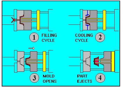
[image:1.612.201.414.536.687.2]The injection moulding has seen steady growth since its beginnings in the late 1800's. The technique has evolved from the production of the simple things like combs and buttons to major consumer, industrial, medical, and aerospace products. The main concept of plastic moulding is placing a polymer in a molten state into the mould cavity so that the polymer can take the required shape with the help of varying temperature and pressure. There are different ways of moulding a plastic some of them are blow moulding, Injection moulding, rotational moulding and compression moulding. Each technique has their own advantages in the manufacturing of specific item. Injection moulding is perhaps the most common and important of all plastic processing processes. The process is extremely versatile, and can produce very complex shaped parts, with the use of multi-sided moulds. While injection moulding dies are expensive to produce, each die can be used to make tens of thousands of components at very rapid rate, so that per-part cost is very low. The cycle of operations during production of a moulded part is as shown in fig 1.1. The moving platen puts the mould together; the mould halves are held with large force, and the molten charge is forced into the cavity; the plastic solidifies, and finally, the moving platen is retracted, and ejector pins in the mould push the part out.
Fig 1.1: Cycle of Operation For Injection Moulding
````
© 2017, IRJET | Impact Factor value: 5.181 | ISO 9001:2008 Certified Journal
| Page 152
1.1. PROBLEM
STATEMENTThe sponsoring company being an ESP (Engineering Service Provider) support assignments in the domain of Design & Development. Further with the competency in Die / Mould Design .It is now working on „Domestic‟ projects for design of Plastic injection mould. One such assignment offered by the client specters the use of thermoplastic as the raw material that would need at least two cavity moulds for meeting the demand. The component design received from the previous stage need to be studied further for evolving the „mould‟ design .The potential problem areas in the form of defects in the moulded component should be minimized through on the part of the mould Design Engineer.
1.2 Objectives
To design the plastic container.
To manufacture plastic container.
To test the plastic container for quality check.
To select the particular material for the application for container.
To design all dimensions of plastic container.
To select the manufacturing process for plastic container.
To test / examine the container or to do check the quality container.
2.1. THE INJECTION MOULDING
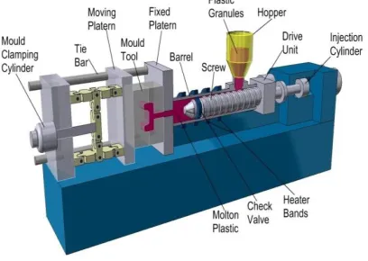
[image:2.612.206.410.397.542.2]Injection moulding is a method of forming a plastic product from powdered thermoplastics by feeding the material through the machine component called the hopper to a heated chamber in order to make it soft and force the material into the mould by the use of the screw. In this whole process pressure should be constant till the material is hardened and is ready to be removed from the mould. This is the most common and preferable way of producing a plastic products with any complexity and size. Injection moulding permits mass production net-shape manufacturing of high precision, three dimensional of plastic parts.
Figure 2.1.1: Injection Moulding Machine
2.1.1. THE INJECTION MOULDING PROCESS
© 2017, IRJET | Impact Factor value: 5.181 | ISO 9001:2008 Certified Journal
| Page 153
The moulding cycle starts with the retraction of the ejector plate, followed by closing of the mould. The injection unit melts the polymer resin and injects the polymer melt into the mould.The ram fed injection moulding machine uses a hydraulically
operated plunger to push the plastic through a heated region. The melt converges at a nozzle and is injected into the mould.
The melt is forced into the mould in two or three stages:
Stage 1: Fill stage
During this stage, the mould cavities are filled with molten resin. As the material is forced forward, it passes over a spreader, or torpedo, within the barrel, which causes mixing. This stage is determined by an injection velocity (rate), a pressure, and a time. Injection velocity is the rate at which the plunger moves forward.
Stage 2: Pack stage
As the melt enters the mould, it cools and introduces shrinkage. The pack stage is necessary to force more melt into the mould to compensate for shrinkage.
Stage 3: Hold stage
When no more material can be forced into the mould, melt can still leak back through the gate. The hold stage applies forces against the material in the cavity until the gate freezes to prevent leaking of the melt. In some machines, pack and hold are combined into a single second or holding stage. Each stage is governed by a particular pressure and time duration, Once the mould is filled and packed and the gate has cooled, the injection moulding machine switches to the cooling stage. The amount of cooling is determined by the cooling time. After the cycle is complete and before the next cycle can be run, the machine must be purged per directions in the manual.
2.2. INJECTION MOULDING MACHINE COMPONENTS
The injection moulding machine consists of the hopper, screw, the barrel and the injection nozzle.
2.2.1. Hopper
In the moulding process the plastic materials are supplied in the form of small pellets. The hopper functions as the holder of these pellets. The pellets are then gravity fed from the hopper to the barrel.
2.2.2. The barrel
The main use of the barrel is to give support for the screw. The Barrel consists of heater bands which function as a temperature recorder for each section of the barrel.
2.2.3. The Screw
[image:3.612.200.406.543.649.2]Also known as the reciprocating screw is used in compressing, melting and conveying the plastic material. The Screw consists of three zones – The feeding zone, the Transition zone and the metering zone. In the feeding zone there will be no change to the plastic materials and they will remain pellets and will be transferred to the next zone which is the transition zone, In this zone melting of the pellets will occur and the molten plastics will be transferred to the next zone which is the metering zone, In this zone the molten material will be ready for injection.
Figure 2.2.1: Different Zones of the Screw
2.2.4. The Nozzle
© 2017, IRJET | Impact Factor value: 5.181 | ISO 9001:2008 Certified Journal
| Page 154
2.3. MATERIAL ANALYSIS2.3.1. Definition and Characteristics of Formation of Plastics
At the very beginning, plastics are assumed to be evolved around 1860, on the trial for material substitution of natural ivory. On literally understanding them, the word plastics come from the Greek word Plasticos, which means to be able to be shaped or moulded by heat. When looking deeper and understand them in a professional and technical way, plastics are generally defined as any material consisting of very large molecules that are characterized by light weight, high corrosion resistance, high strength to weight ratios and low melting point.
Plastics are made from different organic materials such as fossil fuels, petroleum, natural gas, coal and some plant materials, depending on the purpose they are designed in different compositions and mainly categorized as thermoplastics and thermosetting plastics. Plastics are characterized by their ability as a material that can be reshaped and changed in to a desired product using different industrial plastic production methods, such as they can be remoulded, extruded, piped and drawn to extrusion by applying heat and pressure. These plastics are formed by polymerization process through industrial production process and consist of mainly synthetic resins, which is the polymer that constitute in their structure as chained monomers.
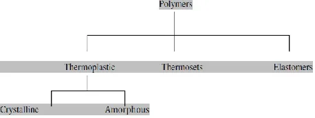
[image:4.612.193.422.321.407.2]Polymers play huge role in the injection moulding process; most polymers are classified into three groups - thermoplastics, thermosets, and elastomers. The thermoplastics can be divided into two types - those that are crystalline and those that are amorphous.
Figure 2.3.1: Classification of polymers
2.4. SOME PROBLEMS ASSOCIATED WITH INJECTION MOULDING
It‟s a common coincidence that defects in injection moulding arise from the mould design imperfection and inappropriate material compounding. Mould seal clearance, inappropriate clamping force and melting temperature along with non-uniform setting times play the major role in lowering the product quality. Besides, the usage of low grade polymer with inappropriate mass–mass ratio would also be a non-conformance in the production of a quality product.
The following below are some of the problems that might arise in the production line. These researches are done by ExxonMobil Chemical Company for the material Polypropylene (PP).This list will highlight problem areas of Injection Moulding and a typical cause and method of resolving that problem.
2.5. PLASTIC INJECTION MOULDS
© 2017, IRJET | Impact Factor value: 5.181 | ISO 9001:2008 Certified Journal
| Page 155
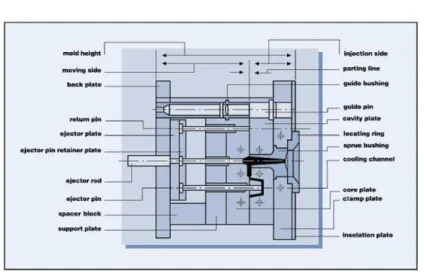
Figure 2.5.1: Impression of a standard injection mould3.1 MATERIAL SELECTION
3.1.1 General Properties of Material
Organic properties of the polymer generally define the properties of the plastic, since the polymer is the basic constituent ingredient in the plastic. Most plastic material show unique properties when compared to other materials due to this chemical structure of the polymer resulting from the bonded monomers. On understanding and further elaboration of the polymer structures, it is a composition of two different base structures as physical or chemical mixtures that are polymeric blends and block copolymers. This can be amorphous or semi crystalline as a result of the molecular structure given by the thermoplastic component.
So, these structures that are given as elaboration and illustration of the plastic structural bonding underneath principle all together the additional substances bonded to the carbon atom of the monomer accounts for the general principles of the resulting plastic properties. As a result of the discussed factors, plastic in general exhibits different physical and chemical properties.
Material Properties
Clear to opaque
Glassy surface
Rigid or foamed
Hard Brittle
High clarity
© 2017, IRJET | Impact Factor value: 5.181 | ISO 9001:2008 Certified Journal
| Page 156
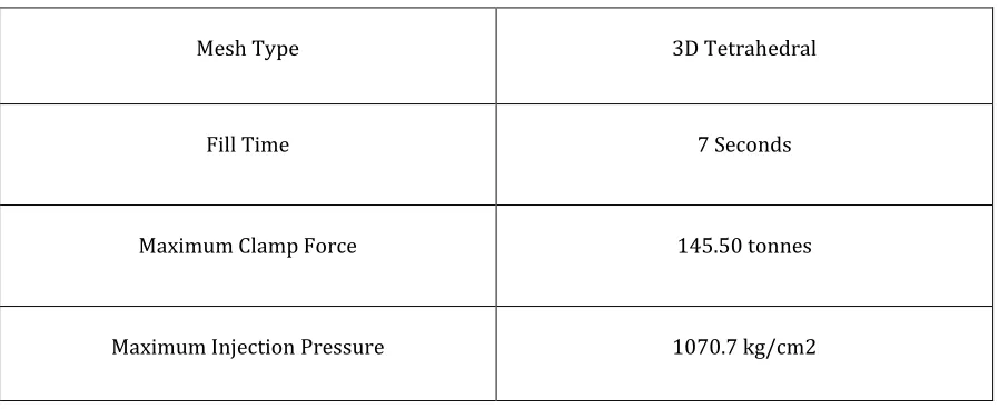
Material Used The power required for this process of injection molding depends on many things and varies between materials used. Manufacturing Processes Reference Guide states that the power requirements depend on "a material's specific gravity, melting point, thermal conductivity, part size, and molding rate." Below is a table from page 243 of the same reference as previously mentioned that best illustrates the characteristics relevant to the power required for the most commonly used materials.
Mesh Type 3D Tetrahedral
Fill Time 7 Seconds
Maximum Clamp Force 145.50 tonnes
Maximum Injection Pressure 1070.7 kg/cm2
4. Methods and Result
In this Part the main details that are discussed are the appropriate designing methods to accomplish the mold design for the required product.
The appropriate steps in designing a mold are 1) Product design
2) Mold design
4.1 Software assistance
Many software can be used in designing the required product with accurate calculations and minimized time spam. - 2D and 3D modeling.
4.2 Product Design
The mold that is designed in this this project is for travelling stool component that can be used for travelling stool as well as normal stool. In today‟s industry we mostly see products as similar as this but almost all of them are made independently ( as a travelling stool component or travelling stool) , But this contains both in one place which is more convenient and solves the common problem of losing once own travelling stool component.
The 2D drawing figure shows the product design for which a mold is designed. The product is made for High Density Polyethylene. The dimensions of this component is 40 mm × 40 mm and thickness of this component is 2 mm. This component is used to plantation.
[image:6.612.83.532.464.648.2]4.4 Parameters Results Table 4.4.1: Parameters Result
4.5 Mould Design
When making a mold design, the following parts should be included Back plate for cavity and core side, Ejector plate, retaining plate, guiding pillars, spacer blocks, cavity plate and core plate.
© 2017, IRJET | Impact Factor value: 5.181 | ISO 9001:2008 Certified Journal
| Page 157
130oC ≤ Tme ≤ 210oC 60oC ≤ Tmo ≤ 80oC 65 MPa ≤ Ppr ≤ 105 MPa
Using the surrogate model and optimisation methodology, the sink depth was minimised. A set of optimised process settings were arrived and it is given under;
Tme = 180 oC ; Tmo = 63oC and Ppr = 105 MPa
When designing a mold, the designer needs to take many factors into account in addition to the actual shape of the mold. Warpage, shrinking, venting, residual stress and runner size are just a few of the factors that must be weighed while in the design stage.
The Full mold in the figure below has a property of steel and includes a back plate that holds the movable side of the mold like spacer block, support plate, cavity plate and ejector mechanism to the movable platen of the injection machine. The design of the back plate for the mold has a dimension of (150mm x 150mm) and a depth of 17.4 mm. Then it‟s the ejector plate often referred to as the ejector covet plate which provides backup for pins set into the ejector-retaining plate.
The retaining comes on top of the ejector plate and functions in holding ejector pins. The travel space for the ejector plates and ejector pins is provided by the spacer block.
To give the plates strength and rigidity it‟s smart to add a support plate. The support plate is followed by the core plate which holds the core element which is the mating half of the cavity.
The core plate is inserted to the cavity which is where the plastic material is formed. To secure the stationary side of the mold to the machine it‟s necessary to have the clamping plate or also known as back plate for the core.
5. EXPERIMENTAL VALIDATION 5.1 INTRODUCTION
A simple and efficient surrogate modelling methodology was developed to predict the sink depth and for minimisation of the same. Developed models were tested statistically as well as through test cases. The main objective of this study was to equip the designer with an efficient yet virtual method to solve issues like sink, which very much require a holistic and integrated approach by combining design variables with processing variables. In order to find out its suitability at the shop floor, an existing part was taken for investigation. The evolved methodology was adopted for minimising the sink depths and it is presented in the following sections.
5.2 VALIDATION OF THE METHODOLOGY
To validate the methodology, a travelling stool component was considered for minimization of sink depth. This component was designed based on the standard design guidelines. Over all size of the component are 87.2 mm × 87.2 mm and 26 mm in height. The plastics material used for the said part was HDPE.
The product before optimizing the process variable is shown in Figure 8.2. This product had been moulded in the traditional way by consulting the guidelines and through experience of the moulder. In this product, the sink marks are clearly visible all along the surface because of the higher thermal mass. The sink marks are marked with arrows for clarity and understanding. The sink depths at the at the surface were measured before the application of the proposed methodology and recorded as 0.038 ± 0.006 mm.
The component was modelled in CAD, as discussed earlier, for constructing the surrogate model. Three processing variables melt temperature (Tme), mould temperature (Tmo) and pack pressure (Ppr) were considered for constructing the final surrogate model. The design variables were not considered due to the requirement of design change approval from the end customer.
© 2017, IRJET | Impact Factor value: 5.181 | ISO 9001:2008 Certified Journal
| Page 158
Figure 6.2.3 (a) Punch of the mouldThe Figure 8.4 (b) shows the punch / fixed half / injection half of the mould. The cavity inserts were also made with the H13 tool steel. The picture in the Figure 8.4 (b) was taken while the mould temperature was measured. The punch half of the mould consists of punch inserts, bolster assembly and the feed system. Both halves were provided with cooling channels for effective maintenance of the mould temperature.
Figure 6.2.4 (b) Cavity half of the mould
While moulding with the optimised settings, flashes appeared at the parting surfaces. Hence, a decision was taken to reduce the mould temperature and it was set at 57oC to arrest the flashes.
[image:8.612.192.421.424.626.2]© 2017, IRJET | Impact Factor value: 5.181 | ISO 9001:2008 Certified Journal
| Page 159
Figure 6.2.5 Improved sample of the componentFigure 8.5 shows the improvement on the product with respect the sink mark after the application of the proposed methodology by fixing the process variables, as deliberated earlier. The sink marks along the ribs were measured. The observed sink depths at surface were found to be 0.026 ± 0.003mm. Figure 8.6 shows the comparative results at a glance. It was observed that the predicted sink depth deviated from the observed value by 0.002 mm. It is noted that
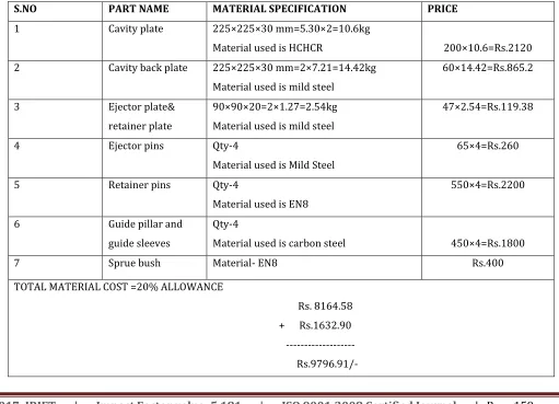
Table 6.1.1: Total Material Cost
S.NO PART NAME MATERIAL SPECIFICATION PRICE
1 Cavity plate 225×225×30 mm=5.30×2=10.6kg
Material used is HCHCR 200×10.6=Rs.2120
2 Cavity back plate 225×225×30 mm=2×7.21=14.42kg
Material used is mild steel
60×14.42=Rs.865.2
3 Ejector plate&
retainer plate
90×90×20=2×1.27=2.54kg Material used is mild steel
47×2.54=Rs.119.38
4 Ejector pins Qty-4
Material used is Mild Steel
65×4=Rs.260
5 Retainer pins Qty-4
Material used is EN8
550×4=Rs.2200
6 Guide pillar and
guide sleeves
Qty-4
Material used is carbon steel 450×4=Rs.1800
7 Sprue bush Material- EN8 Rs.400
TOTAL MATERIAL COST =20% ALLOWANCE
Rs. 8164.58 + Rs.1632.90
[image:9.612.56.567.366.735.2]© 2017, IRJET | Impact Factor value: 5.181 | ISO 9001:2008 Certified Journal
| Page 160
Total Die Cost: Material cost = Rs. 9796.91
Machining cost = Rs. 25060
Transportation = Rs. 1000
Total cost = Rs.35856.91 /-
Total component cost:
Raw material cost = Rs. 1.15/-
Moulding cost = 1.30 Rs/piece
Rejection = (7% on material cost and moulding cost)
Rs.1.45
Profit (12% on cost) = Rs.1.1
[image:10.612.53.513.74.497.2] Total cost = Rs.5/-
Table 6.1.2 Final Product Cost
Price of single component Rs.5/-
No. of components 200000
Cost of components Rs 7,80,000/-
Total cost Rs 10,00,000/-
Net Profit Rs 2,20,000/-
Conclusion By this project we optimize the cost of container by using plastic material & the container is used for various applications like household containers, plant tissue culture.
The Design of the Mold and the processing parameters has an influence over the quality of the component produced.
Hence while designing a mould, the needs to take many factors into account such as material, type of gate selection and position of gate, feed system details like gate size, sprue dimension & runner dimension and various defect such as warpage, sink mark, air traps and weld line, etc.
As per every comparison and market survey we conclude that plastic is suitable material for manufacturing a container.
As per processes comparison and selection manufacturing of plastic container is economical and easy by using plastic injection molding machine.
© 2017, IRJET | Impact Factor value: 5.181 | ISO 9001:2008 Certified Journal
| Page 161
REFERENCES
• All about plastic moulding. 2009. The History of Plastic Moulding. [ONLINE] Available at: http://www.plasticmoulding.ca/history.htm# Plastic. [Accessed 10 October 11]
• Pmold industrial limited. 2010. The injection molding process. [ONLINE] Available at:
http://www.pmolds.com/news/4/15/The-injection-molding-process/ . [ Accessed 18 August 2011 ]
• Machine components. 2009. Injection Systems. [ONLINE] Available at:
http://www.dc.engr.scu.edu/cmdoc/dg_doc/develop/process/control/b1000002.htm. [Accessed24October 11].
• Injection mold making and molding. 2009. Injection mold sprue and runner. [ONLINE] Available at:
http://imoldmaking.com/mold-making-2/mold-design/runner-andgate/injection-mold-sprue-and-runner/. [Accessed 21October 11].
• DSM engineering plastics. 2005. Design guide. [ONLINE] Available at:
http://www.dsm.com/en_US/downloads/dep/designbroch05USweb.pdf [Accessed 31 August 11].
• Plastic Injection Molding Process - A Literature Review Rashi A.Yadav Reserach Scholar, Principal S.V.Joshi, Asst. Prof. N.K.Kamble
• Plastic Manufacturers Survey 2012 West Pier Business Campus, Dún Laoghaire, Co. Dublin.
• International Journal of Modern Engineering Research Prof. S. B. Khedkar1, Prof. R. D. Thakre2, Prof. Y. V. Mahantare3 Vol.2, Issue.5, Sep.-Oct. 2012