© 2017, IRJET | Impact Factor value: 5.181 | ISO 9001:2008 Certified Journal | Page 461
FUZZY BASED BOOST CONVERTER CONTROL FOR WIND ENERGY
CONVERSION SYSTEM
D.Deva Blessy
1, J.Elsi Jasmine
21. P.G.Student, Department of Electrical and Electronics Engineering.
Bethlehem Institute of Engineering, Karungal-629157.
2.
.Assistant professor, Department of Electrical and Electronics Engineering.
Bethlehem Institute of Engineering, Karungal-629157.
---***---Abstract- In this paper the operation of wind turbine system with fuzzy based boost converter control is proposed. Generally
this system consists of wind turbine, variable-speed permanent-magnet synchronous generator (PMSG), AC-DC converter (bridge rectifier+boost converter), battery, and a single phase inverter. Fuzzy logic controller is introduced in the boost converter to maintain constant output voltage. Energy storage devices are required for power balance and power quality in stand-alone wind energy systems. The power can be effectively delivered and supplied to the loads, subject to an appropriate control method. The whole proposed system is developed using MATLAB simulink software.Key Words: Energy storage, real-time control, variable-speed permanent-magnet generators (PMSG), fuzzy logic
controller (FLC), power quality, power balance.1. INTRODUCTION
© 2017, IRJET | Impact Factor value: 5.181 | ISO 9001:2008 Certified Journal | Page 462
II. SYSTEM CONFIGURATION
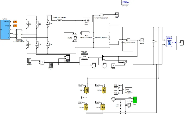
[image:2.595.63.530.346.584.2]The proposed stand-alone wind power system supplies single-phase consumers at 230 V/50 Hz. It is designed for a residential location, and it is based on a 2-kW wind turbine equipped with the following: 1) a direct-driven PMSG; 2) an ac/dc converter (diode rectifier bridge +boost converter with fuzzy control); 3) a LAB storage device; 4) an inverter; 5) a transformer; and 6) resistive loads. The wind power is converted into the mechanical rotational energy of the wind turbine rotor. A wind turbine cannot “completely” extract the power from the wind. Theoretically, only 59% of the wind power could be utilized by a wind turbine but for the 2-kW wind turbine system analyzed in this paper, the real power coefficient is 39%. The wind turbine rotor is connected to the wind generator, thus converting the mechanical energy into electrical energy. The generator’s ac voltage is converted into dc voltage through an ac/dc converter. The rectifier is matching the generator’s ac voltage to the dc voltage, while the boost converter provides the required level of constant dc voltage. As fuzzy based boost converter control is used the stability will be increased. The dc output voltage is fed to the battery bank and through an inverter further to the load. The voltage should stay constant for various wind speeds. When the wind speed is too high, the power excess supplied by the wind turbine is stored in the battery. When the wind speed is low, the generator, together with the battery bank, can provide sufficient energy to the loads. The dc loads are supplied directly from the dc circuit. At high speeds, the turbine control system stops the energy production. The same protection is activated also in the case when the battery is fully charged and energy production exceeds consumption. At low wind speeds, load shedding is used to keep the frequency at the rated value. The storage system is composed of a LAB and a full-bridge single-phase inverter that converts the dc voltage of the battery to ac voltage. Furthermore, this voltage is applied to a single-phase transformer, which boosts up the voltage to 230 V. The inverter controls the power transfer.
Fig. 1. Proposed Fuzzy based WECS
III. WIND TURBINE MODEL
© 2017, IRJET | Impact Factor value: 5.181 | ISO 9001:2008 Certified Journal | Page 463
A generic equation is used to model cp ( , β) is,
IV.PMSG MODEL
The dynamic model of PMSG is derived from the two-phase synchronous reference frame in which the q-axis is 90◦ ahead of the d-axis, with respect to the direction of rotation. The electrical model of PMSG in the synchronous reference frame. where subscripts d and q refer to the physical quantities that have been transformed into the d–q synchronous rotating reference frame; Ra is the armature resistance; ωe is the electrical rotating speed which is related to the mechanical rotating speed of the generator as ωe = np · ωg, where np is the number of pole pairs; and ψPM is the magnetic flux of the permanent magnets. The electromagnetic torque can be derived, as shown below
Te = 1.5np [(Ld − Lq)idiq + ψPMiq] and the electromagnetic torque can be regulated by iq as Te = 1.5npψPMiq.
V.FUZZY BASED BOOST CONVERTER MODEL
The unidirectional boost converter achieves an interface between the battery and the rectifier capacitor and ensures the rapid transfer of power. When Vdc ≥ Vb, the boost converter is not working, and the current provided by the generator is channeled through the bypass Schottky diode Ds.It is assumed that there is no power loss in the converter. The input and output signals of the boost converter are modeled by two controlled current sources The reference current (I Lconv) is supplied by the maximum power point tracking (MPPT). The error between the reference current and the measured current (ILconv) is applied to a proportional integrator (PI) regulator. The output of the regulator is summed with the positive voltage reaction, which realizes Vdc/Vb. The modulation factor D is obtained, which is used as a reference for the PWM generator, The modulation factor provides the control signal for the converter’s switching device ST . In order to control the generator current and to provide over speed limitation, our research team proposed in a control method which is applicable to the dc boost converter block diagram analyzed . Also, the operation of the PMSG rectifier is characterized by variable frequency and variable voltage, as the wind turbine rotor speed varies.
For building a fuzzy block, four main components are needed:
1. Fuzzification: It can convert the input into information that which the inference mechanism use to activate and apply the rules.
2. Rule Base: It contains the description that how to get the good control.
3. Inference Mechanism: It evaluates that which rules of control are relevant to use in this scenario, and
[image:3.595.250.352.617.730.2]4. De-Fuzzification: It can interface that converts the inference mechanism’s conclusion into the control input to the system.
© 2017, IRJET | Impact Factor value: 5.181 | ISO 9001:2008 Certified Journal | Page 464
Fig. 3. Block diagram for fuzzy based boost converter.
The Two inputs should be given to the fuzzy controller of the boost converter. First input is the error in output voltage e[i]= Ref-ADC[i], where ADC[i] is the converted digital value of the 𝑖𝑡ℎ sample of output voltage and „Ref‟ is the digital value corresponding to the desired output voltage. The second input ce[i] = e[i] - e[i-1], is the difference in the error of the 𝑖𝑡ℎ sample and the error of (𝑖−1)𝑡ℎ sample.
[image:4.595.83.513.378.599.2]© 2017, IRJET | Impact Factor value: 5.181 | ISO 9001:2008 Certified Journal | Page 465
Fig 5.plot of membership function for error
[image:5.595.67.530.464.728.2]© 2017, IRJET | Impact Factor value: 5.181 | ISO 9001:2008 Certified Journal | Page 466
PB PS NB ZE NS
NB PB PS NS ZE
NS NB PB PS ZE
ZE NS NB PB PS
[image:6.595.180.408.121.363.2]PS ZE NS NB PB
Table 1.fuzzy rules for boost converter
VI. PERFORMANCE ANALYSIS
The output voltage, simulation, fuzzy rules are discussed in this section. Simulation results shows boost converter operation with fuzzy based control. MATLAB simulation was utilized to perform the simulation for the analysis.
[image:6.595.82.467.476.719.2]© 2017, IRJET | Impact Factor value: 5.181 | ISO 9001:2008 Certified Journal | Page 467
Fig. 7. Output of fuzzy based boost converter
The input which is given to boost converter is 12v and the output which we are getting is 38V. here the input voltage is boosted. This is the output for boost converter.
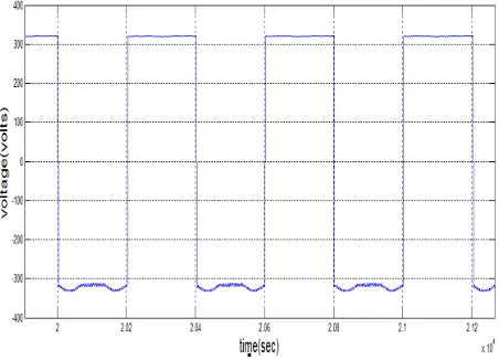
[image:7.595.67.519.401.727.2]© 2017, IRJET | Impact Factor value: 5.181 | ISO 9001:2008 Certified Journal | Page 468
Thus the output voltage with fuzzy based boost converter wind energy conversion system is 230-300V which is suitable for single phase systems.
VII. CONCLUSION
Design of a fuzzy logic controller on boost dc-dc converter by using MATLAB has been successfully achieved. Here the 12 V input for the boost converter is increased into 38.5V. The fuzzy logic controller shows the better performance compared to without using fuzzy logic controller. Using a closed loop circuit with fuzzy logic controller, it is confirmed that the boost dc-dc converter gives a value of output voltage exactly as circuit requirement
ACKNOWLEDGEMENT
The authors would like to express a gratitude especially to Ms.K.Christal saji. ,Associate professor and Head of the Department ,and Mr. Navin sam ,Assistant Professor for the invaluable advice and support that they has given to the authors.
REFERENCES
[1] S. S. Murthy, B. Singh, P. K. Goel and S. K. Tiwari, “A Comparative Study of Fixed Speed and Variable Speed Wind Energy Conversion Systems Feeding the Grid”, in Proc. IEEE 7th Inter. Conf. Power Elect. & Drive Systems, 2007 PEDS '07, 27-30 Nov. 2007, pp. 736-743.
[2]R. A. Mastromauro, M. Liserre, and A. Dell’Aquila, “Control issues in single-stage photovoltaic systems: MPPT, current and voltage control,” IEEE Trans. Ind. Informat., vol. 8, no. 2, pp. 241–254, May 2012.
[3]C. Liu, K. T. Chau, and X. Zhang, “An efficient wind–photovoltaic hybrid generation system using doubly excited permanent-magnet brushless machine,” IEEE Trans. Ind. Electron., vol. 57, no. 3, pp. 831–839,- Mar. 2010.
. [4] M. P. Kazmierkowski, M. Jasinski, and G. Wrona, “DSP-based control of grid-connected power converters operating under grid distortions,” IEEE Trans. Ind. Informat., vol. 7, no. 2, pp. 204–211, May 2011.
[5] P. Palensky and D. Dietrich, “Demand side management: Demand response, intelligent energy systems, and smart loads,” IEEE Trans. Ind. Informat., vol. 7, no. 3, pp. 381–388, Aug. 2011.
[6] V. C. Gungor, D. Sahin, T. Kocak, S. Ergut, C. Buccella, C. Cecati, and G. P. Hancke, “Smart grid technologies: Communication technologies and standards,” IEEE Trans. Ind. Informat., vol. 7, no. 4, pp. 529–539, Nov. 2011. [7]S. Wencong, H. Eichi, Z. Wente, and M.-Y. Chow, “A survey on the electrification of transportation in a smart
grid environment,” IEEE Trans. Ind. Informat., vol. 8, no. 1, pp. 1–10, Feb. 2012.
[8.] R. Teodorescu, M. Lissere, and P. Rodriguez, Grid Converter for Photovoltaic and Wind Power Systems. New York: Wiley, 2011.
[9]E. Monmasson, L. Idkhajine, M. N. Cirstea, I. Bahri, A. Tisan, and M. W. Naouar, “FPGAs in industrial control applications,” IEEE Trans. Ind. Informat., vol. 7, no. 2, pp. 224–243, May 2011.
[10]. L. S Yang and T. J. Liang, “Analysis and implementation of a novel bidirectional DC–DC converter,” IEEE Trans. Ind. Electron., vol. 59, no. 1, pp. 422–434, Jan. 2012.
[11].M. H. Nehrir, C. Wang, K. Strunz, H. Aki, R. Ramakumar, J. Bing, Z. Miao, and Z. Salameh, “A review of hybrid renewable/alternative energy systems for electric power generation: Configurations, control, and applications,” IEEE Trans. Sustain. Energy, vol. 2, no. 4, pp. 392–402, Oct. 2011.
[12.] B. Singh, S. Singh, A. Chandra, and K. Al-Haddad, “Comprehensive study of single-phase AC–DC power factor corrected converters with high-frequency isolation,” IEEE Trans. Ind. Informat., vol. 7, no. 4, pp. 540–556, Nov. 2011.
[13.]L. Barote and C. Marinescu, “Storage analysis for stand-alone wind energy applications,” in Proc. IEEE OPTIM, 2010, pp. 1180–1185.
[14.]L. Barote, R. Weissbach, R. Teodorescu, C. Marinescu, and M. Cirstea,
“Stand-alone wind system with vanadium redox battery energy storage,”- in Proc. IEEE OPTIM, 2008, pp. 407– 412.
[15.] B. Fleck andM. Huot, “Comparative life-cycle assessment of a small wind turbine for residential off-grid use,” J. Renewable Energy, vol. 34, no. 12, pp. 2688–2696, Dec. 2009.
[16.] M. J. Vasallo, J.M. Andújar, C. Garcia, and J. J. Brey, “A methodology for sizing backup fuel-cell/battery hybrid power systems,” IEEE Trans. Ind.Electron., vol. 57, no. 6, pp. 1964–1975, Jun. 2010.
[17.]M. Swierczynski, R. Teodorescu, C. N. Rasmussen, P. Rodriguez, and
© 2017, IRJET | Impact Factor value: 5.181 | ISO 9001:2008 Certified Journal | Page 469
[18]C. Abbey, L. Wei, and G. Joós, “An online control algorithm for application of a hybrid ESS to a wind–diesel system,” IEEE Trans. Ind. Electron.,vol. 57, no. 12, pp. 3896–3904, Dec. 2010.
[19]R. C. Harwood, V. S. Manoranjan, and D. B. Edwards, “Lead–acid battery model under discharge with a fast splitting method,” IEEE Trans. Energy Convers., vol. 26, no. 4, pp. 1109–1117, Dec. 2011.
[20].T. Ackermann, Wind Power in Power Systems. Chichester, U.K.: Wiley,2005.
D.Deva Blessy received her B.E degree in Electrical and Electronics Engineering in 2015 and now studying M.E , Power Electronics and Drives in Bethlahem institute of engineering. Her area of interest includes power electronic devices, power system, electric devices.