http://dx.doi.org/10.4236/jpee.2014.212004
Studies on the Effects of Crystallite Sizes and
Scattering Layers on the Conversion
Efficiency of Dye-Sensitized Solar Cell
Meng-Suan Liang, Yoke-Khey Fong, Chwin-Chieh Khaw, Chin-Chin Liu, Sheue-Pin Chin
Universiti Tunku Abdul Rahman, Kuala Lumpur, Malaysia Email: [email protected]
Received November 2014
Abstract
We have carried out the characterization of dye-sensitized solar cell (DSSC) using various tech-niques including current-voltage characteristic measurements, scanning electron microscopy (SEM), atomic force microscopy (AFM), UV-visible spectrophotometry, energy dispersive X-ray (EDX) spectroscopy and X-ray Diffraction (XRD), etc. The result we obtained from our work has clearly shown that dye adsorption capability of the DSSC is affected by the film thickness. The EDX spec-troscopy verified that our samples are generally of good quality without significant inclusion of foreign elements. The XRD pattern demonstrated that all the TiO2 active layers are consisting of
anatase phase. Our results also showed that smaller crystallite sizes of the TiO2 and inclusion of a
scattering layer produce better efficiency for the DSSC.
Keywords
TiO2, Conversion Efficiency, Crystallite, Scattering
1. Introduction
Renewable power generation covers a wide range of technologies including wind, solar (photovoltaic and ther-mal), biofuels, hydropower, tidal wave, geothermal, and biomass-derived electricity generation. Dye-sensitized solar cell (DSSC) represents a promising technology that has attracted significant attention since it was reported in 1991 [1]-[3]. Dye-sensitized solar cells are the most intensely researched form of renewable energy due to the ease and low cost of fabrication [4]. A dye-sensitized solar cell (DSSC) is a relatively new class of low-cost so-lar cell that belong to the group of thin-film soso-lar cells. It is based on a semiconductor formed between a photo- sensitized anode and an electrolyte, a photo electro chemical system.
In this study, we fabricated DSSCs with different crystallite sizes using various characterization techniques to study the effects of crystallite sizes with scattering layers on the conversion efficiency of the DSSCs.
2. Experimental
2.1. Materials and Fabrication
M.-S. Liang et al.
counter electrode preparation, and cell assembly.
The three dyes, N719, N749 and N3, are purchased from Dyesol. The dyes are in powder form, and are diluted with ethanol or acetonitrile/tert-butanol (1:1 vol:vol).
The conductive side of the FTO glass can be identified with a multi-meter. Marking was made on the non- conductive side using an engraving pen. The FTO glasses are then cut into 2 cm × 2 cm size by using diamond cutter. The glass pieces were washed by using detergent, rinsed with distilled water, de-ionized water, acetone, and ethanol and deionised water again in order to remove all contaminants.
TiO2 nanoparticles are synthesized using the acid-digestion vessels. TiO2 paste was applied on the FTO con-ductive surface by doctor blade techniques. Scotch tape is used to define a one centimetre square area on a cleaned microscope slide. A thin film of TiO2 paste is applied onto the glass plate with a glass rod. The TiO2 thin film left in the ambient for relaxation to reduce surface irregularity. The electrode is then sintered on a hot plate at 125˚C for 6 minutes. The steps above are repeated until the desired thickness is achieved. Normally one or two layers of TiO2 paste A and paste B is enough to get the optimum thickness for high efficiency DSSC. This is followed by another layer of light-scattering TiO2 films containing 400 nm sized anatase particles of 2 - 5 µm. The electrodes coated with the TiO2 pastes were gradually heated under an air flow at 325˚C for 5 minutes, sub-sequently at 375˚C for 5 minutes, followed by 450˚C for 15 minutes and finally at 500˚C for 15 minutes [5]. The electrode is then slow cooled at ambient to around 80˚C. The paste is then shaped into 0.5 cm × 0.5 cm by using a blade and the side is cleaned with ethanol solution to remove the residues. The photo-electrode is then soaked into dye solution for the next 24 hours.
Platinum counter electrode is prepared by drilling a small hole onto a piece of FTO glass. Platinum paste is then applied onto the FTO glass by doctor blade method. The paste is heated at 400˚C for 15 minutes on a hot-plate.
Thermosetting sealant is cut into the size required to seal the electrolyte onto the cell assembly. Attentions have to be taken so that the sealant is not too large which could not seal the glasses properly; or too small that will cover up the drilled hole on the Pt counter electrode. The photo-electrode and Pt counter electrode are as-sembled by melting the sealant at a temperature around 125˚C to 145˚C.
[image:2.595.99.498.647.719.2]Finally, the electrolyte is added through the hole in the back of the counter electrode. A small piece of sealant is used to cover the drilled hole so that the electrolyte is not evaporated from the cell.
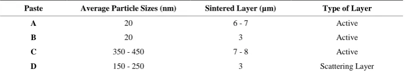
Table 1 shows four different configurations of paste with different article sizes and layer thickness.
2.2. Measurements
The characteristics of the TiO2 film may affect the dye adsorption and consequently influence the performance of the solar cell. Scanning electron microscopy (SEM) and electron diffraction X-ray (EDX) analysis were used to investigate the morphologies, particle and pore sizes and weight ratios of elements for the TiO2 films. X-ray diffraction (XRD) techniques were employed to investigate the influence of thickness on the crystallinity of the TiO2 film. UV-visible spectrometry was utilised to investigate dye loading. An I-V test was used to determine the cell parameters, such as: short circuit current density, Jsc, open circuit voltage, Voc, maximum power, Pmax
and conversion efficiency, η of the DSSCs.
3. Results and Discussion
3.1. XRD
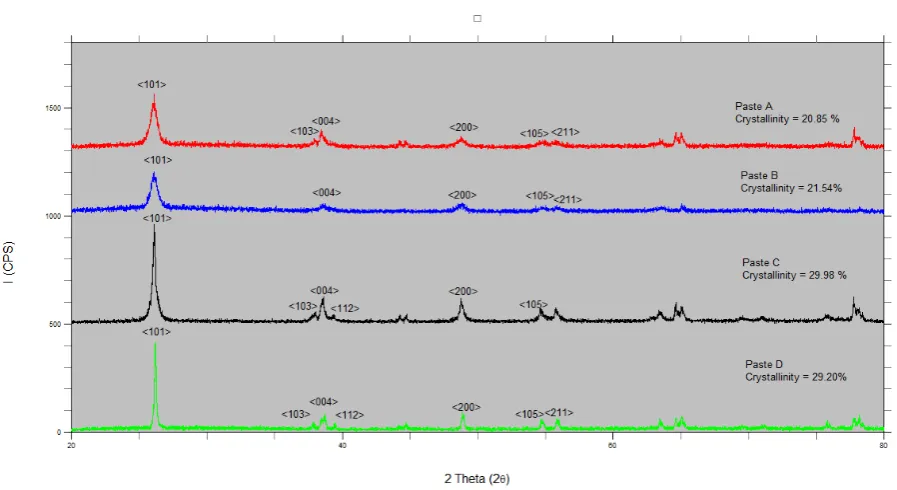
Figure 1 shows the XRD patterns for Paste A, B, C and D respectively. All the results show a unique pattern, however they have similarities in the peak at around 26˚, 38˚, 48˚, 54˚ and 55˚. Paste A has the crystallinity of
Table 1. Particle sizes of the various samples.
Paste Average Particle Sizes (nm) Sintered Layer (µm) Type of Layer
A 20 6 - 7 Active
B 20 3 Active
C 350 - 450 7 - 8 Active
Figure 1. XRD Analysis of TiO2 pastes.
20.85%, paste B has the crystallinity of 21.54%, paste C has 29.98% and paste D has the crystallinity of 29.20%. In general, the better the overall crystallinity of the particle, the better the dye-TiO2 interaction, and the faster the electron injection from the dye to TiO2 [6].
The general trend of the XRD analysis showed that all the TiO2 pastes are in compliance with the JCPDS TiO2 Anatase Phase Standard. Anatase phase has high surface area due to pyramid like crystals therefore opti-mize dye adsorption.
3.2. UV-Visible Spectroscopy
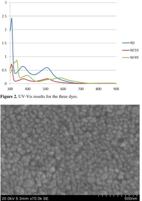
Figure 2 shows the comparison of the wavelength absorption of all dyes. The peak at N3 and N719 is identical to each other. The spectrum of N749 seems to have shifted to the right as compared t the N3 and N719 dye.
Although UV-visible spectra do not enable absolute identification of an unknown, they are frequently used to confirm the identity of a substance through comparison of measured spectrum with a reference spectrum.
As the maximum adsorption wavelength of N3 and N719 dye is 309 nm; and the maximum absorption wave-length of N749 is 338 nm, it correspond to the Anthracene un-substituted ring system existed in the dye.
3.3. SEM and EDX
Figure 3 shows the active layer of TiO2 paste A. The average particle size of paste A is about 20 nm in diame-ter.
In comparison to the Paste D as shown in Figure 4, which has the average particle size of 250 nm particle size, Paste A has much smaller particle diameter. The smaller crystallite sizes have higher surface area for dye particle to adhere thus help improving dye sensitised solar cell performance.
Figure 5 shows the SEM image of cracked surface observed, found on the surface of combination of Paste A + Paste D. The reduction of crack is critical for TiO2 film manufacturing. The existence of the cracks led to lower conductivity and poor light response. Paste D which tends to develop a non-uniform and thicker layer es-pecially at the edge, was found to have cracks on its surface after sintering [7]. This has made the efficiency of combination of Paste A + D lower than Double Layer Paste A and Paste A + C. The same trend is found in the combination of Paste B + D which is lower than double layer Paste B and Paste B + C.
3.4. I-V Characteristics
M.-S. Liang et al.
[image:4.595.152.447.520.706.2]Figure 2. UV-Vis results for the three dyes.
Figure 3. SEM image for the 20 nm paste A.
Figure 5. SEM image of cracked surface found on A + D paste.
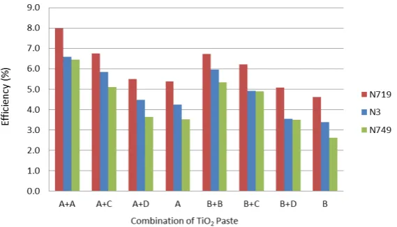
Figure 6. Efficiency of the various TiO2 samples.
layer paste A in N719 recorded the highest efficiency in this study, which is 7.981%. The combination of paste A + paste D gives higher efficiency than the single layer paste A owing to the effect of scattering from paste D. The combination of paste B + paste D gives higher efficiency than the single layer paste B with the same reason. On the other hand, efficiency for combination of paste A + D is lower than the paste A + C because Paste D which tends to develop a non-uniform and thicker layer especially at the edge, was found to have cracks on its surface after sintering. The same trend occurred when comparing the efficiency of paste B + D and paste B + C.
Figure 7 shows that all combination with scattering layer (the right column) has higher efficiency compared to the combination without the scattering layer (the left column). The improvement is due to increase in optical path length resulting in higher amount of light interacting with the sensitizing dye.
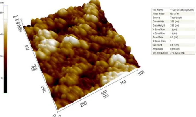
3.5. AFM
The surface morphology taken from AFM probes (Figure 8) shows that the TiO2 films fabricated with doctor blade technique have heterogeneous surface. It clearly demonstrated that nanoparticle TiO2 with a well ordered structure with high surface area.
4. Conclusions
[image:5.595.158.443.306.469.2]M.-S. Liang et al.
Figure 7. Efficiency of various samples incorporated with scattering layers.
Figure 8. AFM image of TiO2 sample.
peak is located at value of around 25.4˚, identified as anatase phase (101). Anatase phase has high surface area due to pyramid like crystals which optimize dye adsorption.
As the maximum wavelength of N3 and N719 dye obtained from UV-vis spectrometry is 309 nm; and the maximum wavelength of N749 is 338 nm, it correspond to the Anthracene un-substituted ring system existed in the dye. Anthracene is commonly used to fabricate dyes, thus the testing result was logic and acceptable.
Titanium oxide film thickness affects dye-sensitized solar cell performance significantly. As the film thick-ness increase, dye adsorption capability increased. The drawback of thicker film is that they are prone to crack-ing.
Scattering layer which has larger particle size is added as a second layer to improve dye-sensitized solar cell performance significantly. Larger particles have more gaps in between particle, which allow more electrolytes to diffuse and adhere to the TiO2 paste. This condition promotes redox couple transport hence increases the light conversion efficiency of dye-sensitized solar cell. However, the distribution TiO2 paste tends to develop a non-uniform and thicker layer especially at the edge, resulting in cracks on its surface after sintering.
[image:6.595.130.470.314.517.2]most abundant element in the sample is Ti and O which are the two major components in titanium oxide. Atomic force microscopy images of the films shows a heterogeneous surface with identical particle sizes. Thus, it can be concluded that our nanoparticle TiO2 layer was successfully fabricated using doctor blade tech-nique and the images showed a well-ordered structure with high surface area.
There are four types of TiO2 paste being utilized in this investigation. Different combination has been tested and among them, the double layer 20 nm particle TiO2 paste gives the highest efficiency of 7.981%. The smaller crystallite sizes have higher surface area for dye particle to adhere to which results in higher efficiency for DSSCs. The use of scattering layers in the solar device is also found to increase performance for the DSSC.
Acknowledgements
We thank the Ministry of Higher Education (MOHE) Malaysia for financial support via the Exploratory Re-search Grant Scheme (ERGS).
References
[1] Sokolsky, M. and Cirak, J. (2010) Dye-Sensitized Solar Cells: Materials and Processes. Acta Electrotechnica et Infor-matica, 10, 78-81.
[2] Wang, Z., Tang, Q., He, B., Chen, X., Chen, H. and Yu, L. (2014) Titanium Dioxide/Calcium Fluoride Nanocrystallite for Efficient Dye-Sensitized Solar Cell. A Strategy of Enhancing Light Harvest. Journal of Power Sources, in Press. [3] Grätzel, M. (2001) Photoelectrochemical Cells. Nature, 414, 338-344. http://dx.doi.org/10.1038/35104607
[4] Hagfeldt, A. and Gratzel, M. (2000) Molecular Photovoltaics. Accounts of Chemical Research, 33, 269-277.
http://dx.doi.org/10.1021/ar980112j
[5] Wang, Q., et al. (2006) Characteristics of High Efficiency Dye-Sensitized Solar Cells. Journal of Physical Chemistry B,
110, 25210-25221. http://dx.doi.org/10.1021/jp064256o
[6] Benko, G., Skarman, B., Wallenberg, R., Hagfeldt, A., Sundstrom V. and Yartsev, A.P. Particle Size and Crystallinity Dependent Electron Injection in Fluorescein 27-Sensitized TiO2 Films. Journal of Physical Chemistry B, 1370-1375. [7] Ito, S., Kitamura, T., Wada, Y. and Yanagida, S. (2003) Facile Fabrication of Mesoporous TiO2 Electrodes for Dye
Solar Cells: Chemical Modification and Repetitive Coating. Solar Energy Materials and Solar Cells, 76, 3-13.