© 2018, IRJET | Impact Factor value: 6.171 | ISO 9001:2008 Certified Journal | Page 2500
MISALIGNED IMAGE INTEGRATION BASED ON CONVEX OPTIMIZATION
Sreelekshmi .B
1, Vidya .N
21
M.Tech, Computer Science & Engineering, Sree Buddha College of Engineering,
Elavumthitta, Kerala, India, 689625
2
Assistant Professor of Computer Science & Engineering, Sree Buddha College of Engineering,
Elavumthitta, Kerala, India, 689625
---***---Abstract -
Images captured by the camera in poor lightingconditions are not suitable for obtaining a clear picture. It will cause blurred or noisy elements in the captured image. It is a serious problem. A new method for obtaining a natural color image under reduced illumination has been proposed here. It is a new method of image integration used to combine two images in order to obtain a natural image under reduced lighting conditions. The long-exposure and the flash images are used as two images for integration. Combining the color details of the long-exposure image with features of the flash image. Most of the existing systems required perfect alignment between pairs of images for integration. However proposed method does not require perfect alignment between flash and long-exposure images. Here express the integration of images as a convex optimization algorithm with primal dual splitting algorithm and produce output image in natural color from high contrast and blurry images.
Key Words: Long-exposure image, Illumination, Image
integration, Correspondence search, Convex optimization.
1. INTRODUCTION
Images obtained from any device such as camera should be clear and it should has natural color for performing various processing and also peoples need clear images with natural color. Users get almost clear image under lighting atmosphere. But it is very difficult to achieve clear image with natural color under poor lighting condition. Clarity of images are very important factor especially under poor lighting condition. However don’t get a clear image with natural color in low illumination. Either get an image with noise or an image with unnatural color. There are numerous methods are used for increasing image quality. However it is a critical task to obtain a clear image from noisy artifacts. An efficient method is using multiple images. They use flash image in addition to long-exposure image. Many methods are used for obtaining a clear image by integrating the image pairs. However these methods have some disadvantages. Some of them needs perfect alignment between image pairs [2], [3]. Some methods are difficult to avoid noisy elements. And some methods are work with misaligned image pair however they are failed if the image pairs have large color differences [4], [5]. Methods used for transferring only color information and produces the resultant image with fake or unnatural color mainly when large illumination variation [6], [7].
A new method can be introduced to solve this problem. The proposed system combining two images and produce an image with clear and natural color. The two images are flash image and long-exposure image [1]. The long-exposure image can be obtained by shaking the camera or through object motion. And the flash image means an image with high contrast. The proposed system is an integration method that combines the color details of the long-exposure image with features of the flash image. In this method use long-exposure image as input. Based on the long-exposure image corresponding flash image can be retrieved from the set. Alignment of both images are also very important. Images having different alignment does not used for integration. The proposed method can also avoid this problem. This system internally process to align one image based other image. If the input image that means long-exposure image is not aligned with flash image in the set then use SIFT (Scale Invariant Feature Transform) operator [11] to align the long-exposure image. If the long-long-exposure image is aligned with flash image then perform further process such as selection of relevant pixels. Here the input image long-exposure image is selected for alignment process based on flash image. Because the long-exposure image contains lots of unwanted pixels. There is no need for processing these unwanted pixels. Only consider reliable pixels from the long-exposure image. After performing SIFT operator, the long-exposure image will be aligned and select only relevant pixels from this aligned exposure image. Then construct a model of long-exposure image, flash image and reliable pixels. Then formulate it as convex optimization and solve convex optimization using Primal Dual Splitting (PDS) algorithm [13] and obtaining the resultant image. The key point of the proposed system is that it does not need perfect alignment between images and also produce resultant image with natural color. The color of the resultant image is same as the color of the long-exposure image. The long-exposure image is an image containing noisy artifacts or blurred image but it contains natural color. So the output image also has natural image like long-exposure image. The output image containing other features which are same as the flash image except the color information. That means the resultant image takes features from both long-exposure and flash image.
2. RELATED WORKS
© 2018, IRJET | Impact Factor value: 6.171 | ISO 9001:2008 Certified Journal | Page 2501 2.1 Image Integration for Dark Scene Restoration
G. Petschnigg, R. Szeliski, M. Agrawala, M. Cohen, H. Hoppe and K. Toyama [2] introduced a method for improving image quality. This method integrates the color image without flash and vivid image contrast flash using a joint bilateral filter. Here, restore an image using a pair of flash / long-exposure images to reset a dark scene. A significant disadvantage of this is that they require a couple of perfectly aligned images, and even some misalignment causes severe degradation in the result.
S. Zhuo, D. Guo and T. Sim [9] introduced a new method to restore a sharp image from a blurry moving image, and flash image consecutively taken by a handheld camera. Using a flash image, this method has some limitations encountered, that is, it is more appropriate for internal static scenes. In addition, the spatially invariant motion blur model cannot grasp times in practice.
2.2 Color Transferring and Colorization Methods
E. Reinhard, M. Adhikhmin, B. Gooch and P. Shirley [6] presented a method of color correction (also called color classification) which transfers the characteristics of the corresponding color statistical characteristics between two images. In this method, which imposes the data points of the mean and standard deviation is a simple operation, which produces credible salient images, the corresponding input images.
F. Pitié, A. C. Kokaram and R. Dahyot [7] suggested color transfer using color histogram analysis. These approaches are based on the approximation of the histogram. However, they do not take careful consideration in the spatial domain, and then the output images tend to have unusual or fake colors, especially when the color of illumination changes spatially.
Y. HaCohen, E. Shechtman, D. B. Goldman and D. Lischinski [4] a new efficient method (known as NRDC) was introduced for color classification. This method recovers reliable local groups of matches between two images with some shared content. One limitation is that difficult to find reliable correspondences in a very large, like the clear sky soft regions. Due to the use of fixed size patches if an object appears on a different background in the two input images, the algorithm cannot extend the regions corresponding to the bounds of the object. A third limitation is that only a global color model cannot handle cases where there are actually two or more different color models finding matches for only one.
Y. Hwang, J. -Y. Lee, I. S. Kweon and S. J. Kim [5] introduced a method to find operator mapping for each color and to achieve precise color transfer by applying the mapping operator. Both methods work well for misaligned images. However, both can fail for images with wide local color or lighting changes.
2.3 Correspondence Algorithms
Correspondence algorithms are a key method in the integration of a misaligned image pair [10]. The classical approaches such as the SIFT operator [11] represents local features in the images by using feature vectors. The SIFT descriptor is invariant to various transformation such as scaling, rotation and robustly works for various lighting conditions.
S. Gould and Y. Zhang [12] introduced a method that address the problem of semantic segmentation, or multi class pixel labeling, by creating a graph of dense overlapping patch correspondences across large image sets. Then based on this patch correspondences, transfer annotations from labeled images to unlabeled images. This method introduce the notion of a PatchMatchGraph which encodes dense patch-based k-nearest-neighbour matches over entire image sets. However, scene level information is currently missing in this method.
3. OVERVIEW
Image quality is a feature of an image that measures the degradation of the perceived image. Resolution is the quality of the image. As the resolution increases, the image becomes clearer. It becomes sharper, more defined and more detailed as well. Images obtained from any device such as camera under a poor lighting environment is not suitable to obtain the image with a clear and natural color. In poor lighting conditions, the resulting image has high contrast or has noisy particles.
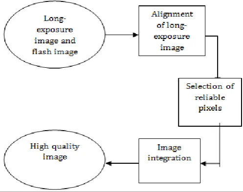
[image:2.595.309.558.543.740.2]To overcome these problems a new image integration approach is proposed for a pair of misaligned images. In this method, the long-exposure image is used as an input to the system. The long-exposure image is obtained from a camera at slow shutter speed [1]. This image is a blurred image due to bad lighting condition. Another image which is a flash
© 2018, IRJET | Impact Factor value: 6.171 | ISO 9001:2008 Certified Journal | Page 2502 image required to perform the process. The flash image is an
image with high contrast due to the presence of flash light. This image can be obtained from the dataset. Selecting the flash image corresponding to the long-exposure image from the data set. This method aims to combine the preferred features in both images to acquire a clear image in a low illumination environment. This approach does not require perfect alignment between images and can produce an image with natural colors and strong contrast even when the illumination of the images largely differ. Fig. 1 shows the block diagram of the proposed system framework. The new framework contains mainly three steps.
1. Correspondence/ similarity search
2. Selection of reliable pixels
3. Image integration using convex optimization
Correspondence search is to find the similarities between long-exposure image and flash image. If two images are not aligned then need to align long-exposure image based on flash image. The best method for the correspondence search is SIFT operator [11]. SIFT can be used to obtain matching pixels between long-exposure image and flash image. Then warping is used to align the long-exposure image based on flash image.
For the selection of reliable pixels, select only the relevant pixels of the long-exposure image which is aligned. A threshold value τ can be used for pixel selection. Then build a model with long-exposure image aligned, flash image and some parameters. This model is a local linear model. And this model can be formulated as a convex optimization problem. Because image processing problems are expressed as convex optimization for an efficient result. PDS can be used as a solution for convex optimization. After performing PDS to the convex optimization function result will be an image with natural color and similar structure of the flash image.
4. CORRESPONDENCE / SIMILARITY SEARCH
The first step of the proposed framework is searching of correspondence or similarity. Sometimes long-exposure and flash images are not perfectly aligned. There are some variations in the images. Both images should contain some common content. But it may not have the same structure. So must have to align the images for integration. If both images are perfectly aligned, then do not have to deal with that. Many algorithms are used for the correspondence search. There are some algorithms which are mainly based on features and patches [8] for this purpose. Feature-based methods often perform better than patch-based methods, so here adopt the SIFT (Scale Invariant Feature Transform) method for robustly detect an initial set of correspondences between the images.
SIFT flow is a method to align an image to its neighbor in a large collection of images consisting of a variety of scenes [11]. The SIFT flow algorithm then consists of combining the densely sampled SIFT characteristics between the two images. SIFT generates 128 feature vectors. SIFT results
matching features between images. Then perform the warping to align the long-exposure image based on the flash image. The image warp is a transformation that applied to the domain of an image, which modifies the geometric characteristicsof the image itself. Warping is done by load the input images. Then find the correspondence and construct a transformation matrix. The input determines the size of the output image. Perform the backward transformation of the matrix again and re-sample pixel values with interpolation. Interpolation is the process of using known data to estimate values at an unknown location. The main application of interpolation is resizing or resampling the image. After performing the interpolation, copy the original image into the deformed image and obtain the result. Then get aligned long-exposure image as the result [1].
5. SELECTION OF RELIABLE PIXELS
The aligned long-exposure image contains unwanted regions. For better integration it is necessary to remove these unwanted regions or pixels from the aligned image. The selection of reliable pixels can be obtained by calculating the difference in the local variance between the aligned long-exposure image Q' and the flash image P. For calculating the difference in covariance for that a square-shaped window (i) centred at the pixel i is constructed. Then the difference in local covariance[1]is calculated by
− │ (5.1)
: = / │ | (5.2)
: = / │ | (5.3)
(5.2) is the local variance [1], and (5.3) is the mean of the pixels in the local window centred at i [1]. ith pixels of
aligned long-exposure image and flash image can be denoted as and respectively. The superscript y indicates the gray-scale image. The number of pixels in the window is constant for all i, which is denoted by | |. If pixels have large difference in aligned long-exposure image then they can be eliminated. Remaining reliable pixels are in subset of S’ [1]defined as
S: =
(5.4)
where S is the set of reliable pixels [1].
6.
IMAGE
INTEGRATION
USING
CONVEX
OPTIMIZATION
6.1 Local Linear Model
© 2018, IRJET | Impact Factor value: 6.171 | ISO 9001:2008 Certified Journal | Page 2503 flash image and the colors of the long-exposure image. This
model processes each color channel independently. Let x, p, and q' (∈ ) represent the vectorized version for each of the three color channels of the processed image X, flash P, and aligned long-exposure image Q', respectively, and N indicates the amount of pixels in a channel. In this system problem is defined as [1]
.
(6.1)
where the function is depend on the LLM. In (6.1),
s S is the pixel index in the correspondence set given in (5.4), and is the mean of x in (i). The LLM used to linearly transform the flash image P with some parameters (shifting and scaling) such as and . The two parameters locally varies, which recognizes the local transfer. The constraint in (6.1) guarantees that the pixels of the resultant image X in the region S have the colors of the long-exposure image. In the end, model (6.1) locally applies the linear transform so that the blurred version of the resultant image matches Q' in the region S [1].
6.2 Convex Optimization
Reformulate this model (6.1) into an unconstrained problem as [1]
(6.2)
where the indicator function is given by
: = (6.3)
When the matrix M∈ {0, 1} is a diagonal matrix for the extraction of pixels, whose diagonal elements are 1 if the pixels are contained in set S. G∈ R is a smoothing filter matrix to calculate the mean value in (i). The functions in (6.2) are convex and their solution can be obtained by using convex optimization algorithms.
The convex optimization problem can be solved by using a first-order division algorithm, called primal-dual partitioning method (PDS) [13]. The main advantage of PDS is that it requires matrix inversion and its computational complexity is relatively short. In this case, the PDS method consists only of multiplications of the matrix and of the simple projection in a convex set. This method based on dividing the original problem into a sequence of iterative sub problems much simpler, involving the functions individually.
A smoothness (or differentiable) function is processed by evaluating its gradient operator, whereas no smooth function is processed by its proximity operator. So such methods are called proximal. The PDS is an optimization algorithm that solves the convex optimization problem of the form [1]
(6.4)
In this case, by setting F: =f (x, a, b), G: = 0, H: =ιCη (x), and L: =MG, the PDS consists of the following steps [1]:
( ,
(6.5)
where “prox” is a proximity operator, and “ ”
can be computed using the following equation [1]
(6.6)
Finally, update x, a, b, z using the procedure in (6.5), and then, the solution x obtained from all the color channels becomes the integration result [1].
7. RESULTS AND ANALYSIS
The experimental results of the proposed method misaligned image integration based on convex optimization are discussed in this section. An application is created using the MATLAB application to implement this technique.
7.1 Results
The algorithm described above is implemented using MATLAB R2013a. In the proposed method implemented using many steps. Input image is a long-exposure image. Based on this input image it is possible to have a flash image. These two images are applied to the first step and then align the long-exposure image. Then the second step selects pixels from the aligned long-exposure image. Final step is to construct a model of flash and aligned long-exposure image and integrate this model and selected pixels to obtain a high quality image as output. Fig. 2 shows the result of various steps discussed above and shows results of high quality image.
7.2 Discussion
© 2018, IRJET | Impact Factor value: 6.171 | ISO 9001:2008 Certified Journal | Page 2504 taken with some device. Also size of the images depends on
output image. Because same image pair size will produce best output than image pair having different sizes. In this method some parameters are used. In reliable pixel selection square shaped window is constructed. After some trial and error radius of the window R=10 and | |=21 X 21. For finding the difference in pixels between aligned long-exposure image and flash image use a threshold vale τ=500. For local linear model construct a window of radius r=8 and ɛ=0.022. And is rearranging each column and row value of
identity matrix then perform sum function on each pixels. Andparameter a is the covariance which is the division of flash and alignedlong-exposure image by adding variance of flash image and ɛ. The variable b is product of difference between the mean value of aligned long-exposure image and a and mean value of flash image. Parameters used in PDS are η=5*10-2, =1 and =1/ (12*, ). For proximity operator
the parameter used for iteration is z=0.1.
7.3 Analysis
In this section analyses the quality of the output image. The quality of the output image depends on mainly three factors. For analysis system uses six images. The main three factors are:
1. Peak Signal to Noise Ratio (PSNR) 2. Relative Mean Brightness Error (RMBE) 3. Relative Structural Similarity (RSS)
1. Peak Signal to Noise Ratio
The PSNR blocks calculates the peak signal-to-noise ratio, in decibels, between two images. This ratio is often used as a quality measurement between the original and a compressed image. The Mean Square Error (MSE) and the Peak Signal to Noise Ratio (PSNR) are the two error metrics used to compare image compression quality. The MSE represents the cumulative squared error between the compressed and the original image, whereas PSNR represents a measure of the peak error. The lower value of MSE, the error will be less. To compute the PSNR, the block first calculates the mean-squared error. MSE is calculated by
(7.1)
Long-exposure image Flash image
Aligned long-exposure image Reliable pixel selection
Image integration
Fig. 2
Results of the proposed method
where M and N are the number of rows and columns in the input images respectively. Then the block computes the PSNR using the following equation:
(7.2)
where R is the maximum fluctuation in the input image data type. Fig. 3 shows the PSNR of six images.
2. Relative Mean Brightness Error
This factor can be used to check the brightness of the output image. For that calculate the mean of long-exposure image and output image. Then calculate the difference between the mean of long-exposure and output image. Reduce result from one. Fig. 4 shows the RMBE of six images.
3. Relative Structural Similarity
© 2018, IRJET | Impact Factor value: 6.171 | ISO 9001:2008 Certified Journal | Page 2505 Fig. 3 PSNR of images
Fig. 4 RMBE of images
Fig. 5 RSS of images
8.
CONCLUSION
The new method is an image integration method for obtaining clear image with natural color. Combination of long-exposureimage and flash image produce a high quality image. The resultant image contains the structure of the flash image and color details of the lone-exposure image. Integration is based on local linear model. LLM used to transfer the color of long- exposure image and combine it in to flash mage. Formulate model as convex optimization problem and it can be solved by using primal dual splitting algorithm. This method restores image with natural color without having any harmful effects to its contrast. The
proposed system consumes more time for producing output. In future design an efficient algorithm for correspondence search and reduce time complexity. Although not always possible for a better output of the proposed system. Because here combine flash and aligned long-exposure image. This long-exposure image having some noisy artifacts. So output may contain little effect on this long-exposure image. In future produce output without having any artifacts.
REFERENCES
[1] Tatsuya Baba, Ryo Matsuoka, Keiichiro Shirai and Masahiro Okuda, “Misaligned Image Integration With Local Linear Model,” IEEE Transactions on Image Processing, vol. 25, NO. 5, May 2016.
[2] G. Petschnigg, R. Szeliski, M. Agrawala, M. Cohen, H. Hoppe and K. Toyama, “Digital photography with flash and no-flash image pairs,” ACM Trans. Graph., vol. 23, no. 3, pp. 664–672, Aug. 2004.
[3] H.-J. Seo and P. Milanfar, “Robust flash
denoising/deblurring by iterative guided filtering,” EURASIP J. Adv. Sig. Process., vol. 2012(1), no. 3, pp.1–19, 2012.
[4] Y. HaCohen, E. Shechtman, D. B. Goldman and D. Lischinski, “Nonrigid dense correspondence with applications for image enhancement,” ACM Trans. Graph., vol. 30, no. 4, pp. 70:1–70:10, 2011.
[5] Y. Hwang, J. -Y. Lee, I. S. Kweon and S. J. Kim, “Color transfer using probabilistic moving least squares,” in Proc. IEEE Conf. CVPR, Jun. 2014, pp. 3342–3349.
[6] E. Reinhard, M. Adhikhmin, B. Gooch and P. Shirley, “Color transfer between images,” IEEE Comput. Graph. Appl., vol. 21, no. 5, pp. 34–41, Sep. /Oct. 2001.
[7] F. Pitié, A. C. Kokaram and R. Dahyot, “N-dimensional probability density function transfer and its application to color transfer,” in Proc. IEEE ICCV, Oct. 2005, pp. 1434–1439.
[8] C. Barnes, E. Shechtman, D. B. Goldman and A.
Finkelstein, “The generalized PatchMatch
correspondence algorithm,” in Proc. ECCV, 2010, pp. 29–43.
[9] S. Zhuo, D. Guo and T. Sim, “Robust flash deblurring,” in Proc. IEEE Conf. CVPR, Jun. 2010, pp. 2440–2447.
[10] C. Liu, J. Yuen, A. Torralba, J. Sivic and W. T. Freeman, “SIFT flow: Dense correspondence across different scenes,” in Proc. ECCV, 2008, pp. 28–42.
© 2018, IRJET | Impact Factor value: 6.171 | ISO 9001:2008 Certified Journal | Page 2506 [12] S. Gould and Y. Zhang, “PatchMatchGraph: Building
a graph of dense patch correspondences for label transfer,” in Proc. ECCV, 2012, pp. 439–452.
[13] L. Condat, “A primal–dual splitting method for convex optimization involving Lipschitzian, proximable and linear composite terms,” J. Optim. Theory Appl., vol. 158, no. 2, pp. 460–479, Aug. 2013.
[14] A. Levin, D. Lischinski and Y. Weiss, “A closed-form solution to natural image matting,” IEEE Trans. Pattern Anal. Mach. Intell., vol. 30, no. 2, pp. 228– 242, Feb. 2008.
BIOGRAPHIES
Sreelekshmi B received Diploma in Computer Engineering from NSS Polytechnic College, Pandalam, in 2013. She has received B. Tech from Sree Buddha College of Engineering, Ayathil, in 2016. She is studying M.Tech in Sree Buddha College of Engineering, Ayathil.