4441
EVOLUTION OF STRUCTURE, MORPHOLOGY
AND GROWTH OF CNS’S AS A FUNCTION OF
PRE-ETCHING TIME DEPOSITD BY RF-PECVD
B. Purna Chandra Rao, G. Ramesh Babu, V. Himamaheswara Rao,d D. John Thiruvadigal
Abstract- This paper reports the growth of different types of carbon nanostructures on Si (100) substrates including spherical carbon nanosheets, carbon nanorods and nano-shell like novel morphological carbon nanostructures by Radio Frequency Plasma Enhanced Chemical Vapor Deposition. Methane, Argon and Iron were used as the source of carbon, plasma and catalyst respectively. We studied the growth, structural, morphological and chemical composition of the carbon nanostructures as function of time of pre-etching. While AFM characterized the morphology of the deposited catalyst films after the free etching reaction, FE-SEM helped to examine the morphology, size and density of as grown carbon nanostructures after the synthesis. Chemical composition of the sample was studied by EDS. The presence of defects and structural analysis were examined by Raman Spectroscopy .Energy Dispersive Spectroscopy shows the presence of more atomic and weight percentage of carbon in the sample grown after 60 minutes pre-etching process compared to the samples grown after 30 and 120 minutes pre –etching process. Raman Spectroscopy indicates the decrease of I (D)/I (G) value after 60 minutes pre –etching process where as increase of I(D)/(G) value after 30 and 120 minutes pre etching process.
Index Terms- RF-PECVD, AFM, FE-SEM, Carbon nanosheets, Carbon nanorods, Carbon nanoshells and Raman Spectroscopy
————————————————————
1.INTRODUCTION
After the discovery of fullerenes by Kroto and Smalley in the year 1985 [1], research on allotropies of carbon has become a wider area to understand the formation of many carbon nanostructure configurations and their potential applications. Among these allotropies of carbon, fullerenes and nanotubes have closed surfaces due to the participation of pentagon rings [2]. On the other hand, nanogrphites are characterized by the stacking of finite flat graphene sheets having open edges. It has been pointed out that the electronic properties of nanographites are greatly influenced by their edge shapes apart from quantum size effects and surface effects [3],[4].These graphite sheets and carbon nanostructures may have potential applications, such as serving as catalyst support [5], [6] electrode materials for lithium ion batteries [7] and electronic conducting fillers for conducting polymer composites[8], [9], [10] because of their remarkable surface area as well as special characteristics of flexibility and electricity, high thermal resistance and high chemical stability and light weight [11]. In addition, this quasi-two-dimensional nanostructured materials may serve as the building blacks for other promising carbon nanomaterials. For instance, nano tube–like carbonscrolls have been formed from exfoliated graphite nanosheets via a scrolling mechanism [12]. Most nanostructures derive their configurations from topological defects in grapheme sheets, and the energetically need to eliminate the dangling bonds by folding in on themselves [13], carbon nanohorns are a new type of horn-shaped aggregate of single graphene sheets[14].
_____________________
B. Purna Chandra rao, Professor of physics PACE Institute of Technology and Sciences ongole, AP-523272, India.
G. Ramesh Babu, Assistant professor of physics PACE Institute of Technology and Sciences ongole ,AP, India.
V. Himamaheswara Rao, Assistant professor of physics PACE Institute of Technology and Sciences ongole , AP ,India.
D. John Thiruvadigal,Dean Research, SRM University,
Kattankulathur -603203, India. Email
correspondence:[email protected]
In some early studies [15], [16], [17], carbon nanosheets and carbon nanorods were produced with low yields accompanying other carbon allotropy such as carbon nanotube. Recently, petal-like carbon nanosheets in a macroscopic quantity by an arc – discharge reaction [18], and expanded graphite (EG) nanosheets were produced from various graphite interaction compounds submitted to the a brutal thermal shock[19],[20],[21],[22].However, there is a lack of well-separated, positional grown carbon nanostructures particularly in the case of micro electronic device fabrication. There are certain methods like micro wave plasma enhanced chemical vapor deposition and hot filament chemical vapor deposition methods [23],[24],[25],[26] were reported for the growth of individual carbon nanostructures, but these methods, however, required high temperatures.RF-Plasma Enhanced Chemical Vapor deposition is probably the most suitable carbon nanostructure growth method because of it is relatively simple and has a high reliability than other methods. RF-PECVD used here, offers the variation of growth parameters like gas composition, substrate temperature, RF-power and the pressure of the reactions respectively. This paper reports the growth of different types of individual carbon nanostructures under the same reaction conditions like spherical carbon nanosheets, carbon nanorod like structures and the growth of novel morphological individual nanoshell like structures, growthmode of these nanoshell like structures is still under investigation. We try to evaluate the growth, structural, morphological and elemental composition of the grown carbon nanostructures as function of time of pre-etching.
2 EXPERIMENTAL
deposition technique equipped with well digital thickness monitor for the deposition of iron thin film on Si substrates. The three Si (100) substrates were transformed to e-beam physical vapor deposition chamber to coat 10 nm thick iron film. We fixed the evaporation rate of the Iron at 0.1A0 /sec, Chamber Pressure at 10-6 mbar in the room temperature.
Fig.1 shows the black diagram of the Radio Frequency Plasma Enhanced Chemical vapor deposition.
The samples were then kept in evacuated vessel under primary vacuum. Then we transformed each sample in to the RF-PECD chamber for heating process to activate the catalyst thin film. We conducted three –pre etching reactions, in sequence, in which one experiment for 30 minutes, one for 60 minutes and the other for 120 minutes pre-etching reactions . In addition, in each experiment of pre-etching reaction substrate temperature, RF-power and Argon flow rate were maintained at 7000 C, 500 W and 60 sccm respectively. To investigate the morphology, size and density of the activated catalyst samples we used Agilent’s technologies Atomic Force Microscopy fixed in taping mode.For growth of carbon nanostructures, we conducted three sequential experiments again, in which one experiment for 30 minutes, one for 60 minutes and the other for 120 minutes pre-etching reactions respectively. While synthesizing , in all the three experiments, the substrate temperature, RF- power and time deposition were kept at 7000C, 500 W and 20 minutes respectively. The flow rates of Argon and methane were fixed at 20 sccm and 80 sccm respectively. Flow rates of Ar and Methane were maintained by Mass flow controllers equipped with the Chamber of RF-PECVD. FEI Quanta- 200 field emission scanning electron microscopy equipped with Energy Dispersive Spectroscopy investigated morphology, size and elemental analysis of carbon nanostructure samples. We used Raman spectroscopy (HORIBA HR 800 UV; Helium Laser 632 nm) for the structural analysis and identification of defects in the samples.
3. RESULTS AND DISCUSSIONS
From figure 2a, it is observed that less density of the nucleation is seen in the 30 minutes pre-etching sample after PE-CVD process. It also observed that most of the grown carbon nanostructures are spherical in shape covered with maximum amount of amorphous carbon. The measured size of the carbon nano structures is roughly around 300 to 350 nm. Whereas comparatively high growth of carbon nanostructures have seen in the sample after 60 minutes pre-etching, figure 2b. Here, maximum area of the sample occupies near two -dimensional rod shaped carbon nano structures with high lengths and low diameter compared to the 30 minutes pre-etching sample.
Fig. 2 FE-SEM images of carbon nano structures grown on Si (100) substrates coated with 10 nm Fe-thin film (a) after 30 minutes pre-etching, (b) after 60 minutes pre-etching and (c) after 120 minutes respectively.
The measured length of the grown carbon nanostructures is around 200 nm and the diameter of the grown carbon nanostructures is around 100 nm respectively. It is also identified that the density, growth and orientation of the grown carbon nanostructures increases from 30 minutes to 60 minutes pre etching. Nevertheless, agglomerated growth of the carbon nanostructures is observed after 120 pre-etching as shown from figure 2c. The growth almost appear as foam covered with carbon that is more amorphous. To examine the role of pre-treatment and its correlation with carbon nano structures growth, changes of morphologies on the substrates after the pre-treatments were observed by AFM.
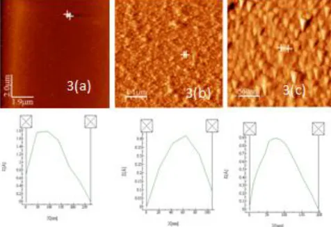
Fig.3.AFM images with corresponding line profiles of Fe-deposited Si (100) substrates with a thickness of 10nm (a) after 30 minutes etching, (b) after 60 minutes pre-treatment and (c) after 120 minutes respectively. The other parameters like substrate temperature, RF-power and Argon flow rate maintained at 7000 C, 500 W and 60 sccm respectively.
4443 seen from the 120 pre-etching sample, as shown by figure 3c,
it is identified that there is an increment in the size of the granules compared to the 60 minutes pre-etching sample, measured size of the granules is roughly about 200 nm. It is explained that, the time of reaction is double than the previous reaction and hence, the above-mentioned two processes of the reaction will occurs even more time. Therefore, longer pre-treatment time brought about coalescence of the particles due to Ostwald ripening that resulted in the formations of the heavier granules. Perhaps, in this case, Even though the pre etching time is 120 minutes but the size of the granule is less compared to the 30 minutes that represents that the granules not exactly agglomerated and acquires the continuous layer like morphology.
In this work, we are trying to bring out the interrogation of the change in morphology, size, density, growth and crystalline nature of the grown carbon nano structures as a function of pre etching time. As the progression of this work to realize the above-mentioned changes, we have performed the high magnification scanning of the samples using Field Emission Scanning Electron Microscopy. Fig.4. shows the high magnification FE-SEM images of the all the three samples.
Figure 4.High magnification FE-SEM images of the carbon nanostructures grown on Si (100) substrates coated with Fe- with a thickness of 10 nm (a) 30 minutes pre-etching,(b)after 60 minutes pre-etching and (c) after 120 minutes prep-etching respectively. The other parameters like substrate temperature, RF-power and Argon flow rate maintained at 7000 C, 500 W and 60 sccm respectively.
It is believed that nanostructures grow by the decomposition of the carbonaceous gas on the surface of a catalyst granule. The carbon dissolves in the catalyst, diffuses through it, and exit to form of the carbon nano structure. In the case of the 30 minutes pre-etching sample the catalyst granules breaks in to in to three-dimensional spherical shaped structures as shown in figure 1a.The carbon nucleation takes place across the hole surface of the catalyst granule and hence resemblances the shape, one can clearly seen from high magnification FE-SEM shown in figure 4a. The presence of less denser island like structures other than the spherical structures is due to the uneven breaking of catalyst film during 30 minutes pre-etching. Whereas two –dimensional rod shaped structures were clearly observed from figure 4b taken by high magnification mode of FE-SEM. The shape proportionate the shape of the catalyst granule shown in figure 1b.Nerverrthless, carbon foam like growth is observed from figure 4c taken for 120 minutes pre-etching reveals the corrugation behavior of the catalyst granules observed from figure 1c.However, the change in the shape is most probably related to the dissolution, precipitation, and the saturation of the carbon in to Fe. The less diameter growth of the two-dimensional rod shaped carbon structures caused by the nucleation of the carbon nanostructures from sharp edged
less diameter catalyst granules as shown in figure 2a.Need of more number of carbon radical to attain the saturation state and to extrude from surface of the catalyst granule. Whereas the carbon nanostructure nucleates from the sharp edged granules precipitates and extrudes easily from the surface of the catalyst. Which intern supports to improvement in the length of the carbon nanostructures. Formation of large sized carbon nanostructures with poor growth behavior is -observed from 30 minutes and 120 minutes pre etching sample. This is probably because the large catalyst granules serves like continuous catalyst thin film during the carbon nanostructure growth and as a result, gives a growth of large sized structures like that of the continuous film. This supports the non-linear growth behavior of the carbon nanostructures with catalyst granule size. Generally, the formation of more dense carbon nanostructures in higher pre -etching samples is the presence of dense catalyst granules.
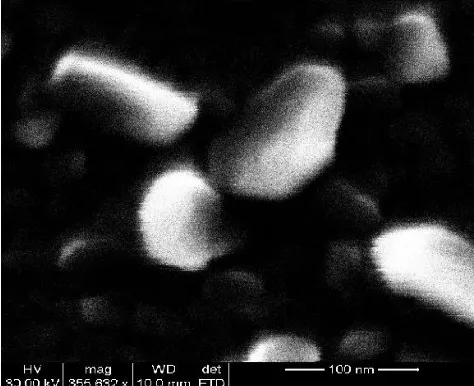
Fig.5 Ultrra high magnification FE-SEM image of the novel shaped carbon nanostructures imaged from particular area of the 60 minutes pre -etching sample after PE-CVD process.
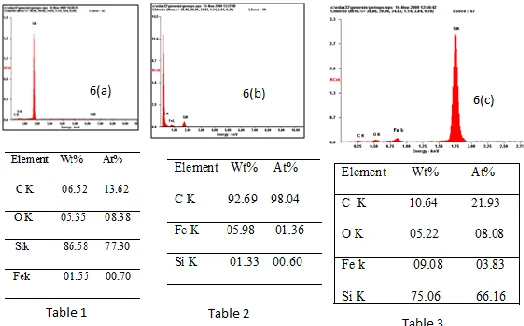
Fig .6 a, b and c Energy Dispersive Spectroscopy graphs of Fe-catalyzed carbon nanostructures grown on Si(100)with catalyst thickness of 10 nm, pre-etching times of 30 ,60 and 120 minutes respectively. Tables 1,2 & 3 Chemical composition of the samples in three different pre-etching reactions respectively.
One can clearly seen the presence of high atomic and weight percentages of carbon is observed from 60 minutes pre-etching sample compared to the remaining two cases. It is known that carbon nanostructures growth strongly depends on the formation of catalyst granule and enough granulation of catalyst film results in enhancement of carbon nano structures growth (27).This is because carbon diffusion across metal particles is a rate-limiting step (28).Carbon atoms formed by decomposition of hydro carbon gases such has methane used in the study dissolves in to the metal particle. When super saturation of carbon in the metal occurs, the carbon atoms extruded from the particles and growth of the structures occurs. In the case of fine sized catalyst granules after 60 minutes pre-etching, saturation process occurs very quickly than the other two cases. Insufficient or wider size formation of catalyst granule causes instauration and slow precipitation of the carbon radical on the catalyst surface. This intern causes the presence of amorphous carbon, excess of oxygen and iron content in the grown carbon nano structures. Results shown in the three tables, from figure 6, one can clearly seen the presence of more oxygen content after low and high Pre-etching samples. Whereas, zero oxygen content is observed from 60 minutes pre-etching sample. This shows us the formation of oxide layer in the samples grown after less and more time pre –etching process. Even though we studied the crystalline nature and morphology of the grown carbon nano structures with Energy Dispersive Spectroscopy since carbon is a Raman active element, Raman Spectroscopy is the useful nondestructive method for the structural analysis of different carbon materials (29). Raman spectra taken on carbon nano structures as shown in Fig.7 are similar to those observed for carbon nanotubes. Fig.7 shows Raman spectra of carbon nano structures grown after different pre- etching reactions (same samples as inFig.1). All the samples shows a peak at 1321cm-1 in the D-band (Defects) which is associated with vibrations of carbon atoms with dangling bonds in plane terminations of the disordered graphite.
Fig.7. a, b and c Raman Spectroscopy graphs of Fe-catalyzed carbon nanostructures grown on Si(100)with catalyst thickness of 10 nm, pre-etching times of (a) 60 minutes,(b) 30 minutes and (c) 120 minutes respectively. The peak at 2639 cm-1 is an over tone of the disordered graphite [2xD]. The peak at 1576 cm-1 (g-band) is attributed to the vibration of sp2 – bonded carbon atoms in a two dimensional hexagonal lattice [30, 31]. From figure 7 It is observed that the ratio of I(D)/I(G) value is less after 60 minutes pre-etching reaction compared to 30 minutes and 120 minutes pre –etching reactions. This represents the presence of well-crystallized graphitic carbon in the carbon nanostructures grown after 60 minutes pre-etching. It is referred that the alignment of the carbon nanostructures in RF-PECVD results from the influence of the electric field created by plasma also known as sheath(32). It is also known that the electric field in the sheath is always preferred to direct towards sharp edged or fine sized surface catalyst particles, this helps the carbon radical to settle in alignment fashion during the growth of carbon nanostructures. It leads to the carbon species dissolves, saturates and then precipitates as graphite, as much as faster in the case of fine catalyzed particles after 60 minutes pre-etching than the other two cases.
4. CONCLUSIONS:
4445 The change observed in the morphology of the carbon
nanostructures from spherical to rod and foam like shapes from 30 to 60 minutes and to 120 minutes reveals the fact of dissolution, precipitation and saturation of carbon on Iron catalyst. The good correspondence in structural and elemental analysis of the grown carbon nanostructures of both Energy Dispersive Spectroscopy and Raman spectroscopy 30 to 60 and to 120 minutes pre- etching is related to the fact that in the fine sized catalyst granules after 60 minutes pre-etching, saturation occurs very quickly than the other two cases. In sufficient or wider size formation of the catalyst granules causes in saturation and slow precipitation of the carbon radical on the catalyst surface, this intern causes the presence of amorphous carbon, excess of oxygen in the grown carbon nanostructures. More defective behavior of the grown carbon nanostructures after 30 minutes and 120 minutes pre-etching compared to the 60 minutes pre-etching which we correlated to the presence of more number of impurities from EDS analysis is also supports the influence of the electric field created by the plasma also known as the sheath in case of 60 minutes pre-etching. In addition, we also reported the growth of the nano shell like novel morphological carbon nanostructures the growth mode is yet to be analyzed.
5. ACKNOWLEDGEMENTS
The authors gratefully acknowledge the Nanotechnology Research Center; SRM University for their support to synthesize carbon nanostructures using radio frequency plasma enhanced chemical vapor deposition
6. REFERENCES:
[1] H.W. Kroto, J.R. Heath, S.C. O’Brien, R.F. curl, and R.E. Smaelly, Nature, vol. 318, pp. 162, 1985.
[2] M.S. Dresselhaus, G.Dresselhaus, and P.C. Eklund, Science of Fullerenes and Carbon nanotubes (Acadamic, San Diego, 1996).
[3] M. Fujita, K. Wakabayashi, K. Nakada, and K. Kusakabe, J. Chem. Phy., vol. 65, 1920, 1996. [4] K. Nakada, M. Fujita, G. Dresselhaus, and M.S.
Dresselhaus, Phys. Rev. B. vol. 54,17 954 (1996). [5] B.J. Yang, Y.H. Wu. B.Y. Zong, Z.X. Shen, Electro
chemical synthesis and characterization of magnetic nano particles on carbon nano wall templates, Nano Lett., vol. 2, pp. 751-754, 2002.
[6] N. Kariya, A. Fukuoka, T. Utagawa, M. Sakuramoto, Y. Goto, M. Ichikawa, Efficient hydrogen production using cyclo hexane and declaine by –spray mode reactor with pt catalysts, Appl. Catal. A-Gen., vol. 247, pp. 247-259, 2003.
[7] J. Stantos-Pena, T. Brousse, D.M. Schleich, Search for the suitable matrix for the use of ztin-based anodes in lithium ion batteries, Solid State Ionics, vol. 135, pp. 87-93, 2000.
[8] Y.X. Pan, Z.Z. Yu, Y.C. Ou, G.H. Hu, A new process of fabricating electrically conducting nylon 6/ graphite nanocomposites via intercalation polymerization, J Polym. Sci. Pol. Phys., vol. 38, pp. 1626-1633, 2000. [9] G.H. Chen, D.J. Wu, W.G. Weng, W.L. Yan,
Dispersion of graphite nanosheets in a polymer matrix and the conducting properties of nanocomposites, Poly. Eng. Sci., vol. 41, pp. 2148-2154, 2001.
[10] G.H. Chen, D.J. Wu, W.G. Weng, C.L. Wu, Exfoliation of graphite flakes and its nano composites, Carbon, vol. 41, pp. 619-621, 2003.
[11] T.J. Manning, M. Mitchell, J. Stach, T. Vicker, Synthesis of exfoliated graphite from fluorinated graphite using an atmospheric –pressure argon plasma. Carbon, vol. 37, pp. 1159-1164, 1999 [12] L.M. Viculis, J.J. Mack, R.B. Kaner, A chemical root to
carbon nano scrolls, Science, vol. 299, pp. 1361-1371, 2003.
[13] S Iijima, M Yudasaka, R Yamada, S Bandow , K Suenaga, F Kokai, et al., Nano aggregates of single – walled graphite carbon nano horns, Chemi. Phys. Lett., vol. 309, pp. 165-170, 1999.
[14] Y.H. Wu, P.W. Quiao, T.C. Chong, Z.X. Shen, Carbon nano walls grown by microwave plasma enhanced chemical vapor deposition, Adv. Mater., vol. 14, pp. 64-67, 2002.
[15] T.W. Ebbeson, P.M. Ajayan, Large scale synthesis of carbon nanotubes, Nature, vol. 358, pp. 220-222, 1992.
[16] Y. Ando, S Iijima, Preparation of carbon nanotubes by arc discharge Evaporation, J. Appl. Phys., vol. 32, pp. 107-109, 1993.
[17] S. Iijima, T. Wakabayasi, M. Tomita, T. Hayashi, Structures of carbon soot prepared laser ablation. J.
Phys. Chem., vol. 100, pp. 5839-43, 1996
[18] Y. Ando, X. Zhao, M. Ohkohchi, Production of peatel like graphite sheets by hydrogen arc discharge, Carbon, vol. 35, pp. 153-8, 1997.
[19] T. Nakajima, Y. Matsuo, Formation process and structure of graphite oxide, Carbon, vol. 32, pp. 469-75, 1994.
[20] A. HeRold, D. Pertitean, G. Furdin, M. Klatt, Exfoliatation of graphite intercalation compounds: classification and discussion of the process from new experimental data relative to graphite- acid compounds, Mater. Sci. Forum, 152-153, 1994. [21] A. Celzard, M . Krzesinska, D. Begin, J.F. Mareche,
S. Puricell, G. Furdin, Preparation, electrical and elastic properties of new anisotropic expanded graphite-based composites, Carbon, vol. 40, pp. 557-66, 2002.
[22] G.Q. Liu, M .Yan, The preparation of extended graphite using fine flake graphite, New Carbon Mater., vol. 2, pp. 355-9, 2002.
[23] Y.H. Wu, B.J. Yang, Effects of localized electric field on the growth of carbon nanowalls, Nano Lett.,vol. 2, pp. 355-59, 2002.
[24] R. Kurt, J.M. Bonard, A. Karimi, Morphology and field emission properties of nanostructured nitrogenated carbon films produced by plasma enhanced hot filament CVD, Carbon, vol. 39, pp. 1723-30, 2001. [25] Y.H. Wu, B.J. Yang, G.C. Han, B.Y. Zong, H.Q. Ni,
Luo P, et al. Fabrication of class of nanostructured materials using carbon nanowalls as the templates, Adv. Funct. Mater., vol. 12, pp. 489-94, 2002.
[27] M. Chhowalla, K.B.K. Teo, C. Ducati, Rupesinghe, G.A.J. Amaratunga, A.C. Ferrari, et al. J. Appl. Phys., vol. 90, pp. 5308, 2001.
[28] C. Ductai, I. Alenxandrou, M.Chhowalla, N.L. Robertson, G.A.J. Amaratunga, Appl. Phys., vol. 95, pp. 6387, 2004
[29] M. S. Dresselhaus and P. C. Eklund, Adv. Phys., vol. 49, pp. 705, 2000.
[30] J.W. Liu, M.W. Shao, X.Y. Chen, W.C. Yu, X.M. Liu, Y.T . Qian, Large synthesis of carbon nanotubes by an ethonal thermal reduction process, J. Am. Chem. Soc., vol. 125, pp. 8088-9, 2003.
[31] J. Liu, M.W. Shao, Q. Tang, S.Y. Zhang, Y.T. Qian, Synthesis of carbon nanotubes and carbon nanobelts through medical –reduction method, J. Phy. Chem. B., vol. 107, pp. 6329-32, 2003.