Stressed Rocks, Under Simulated Crystal Conditions
Studied by Pore Volumometry.
by
Peter Charles Aves.
A thesis submitted to the University of London
for the degree of Doctor of Philosophy.
Dept, of Geological Sciences, September 1995.
All rights reserved
INFORMATION TO ALL USERS
The quality of this reproduction is dependent upon the quality of the copy submitted.
In the unlikely event that the author did not send a complete manuscript and there are missing pages, these will be noted. Also, if material had to be removed,
a note will indicate the deletion.
uest.
ProQuest 10017156
Published by ProQuest LLC(2016). Copyright of the Dissertation is held by the Author.
All rights reserved.
This work is protected against unauthorized copying under Title 17, United States Code. Microform Edition © ProQuest LLC.
ProQuest LLC
789 East Eisenhower Parkway P.O. Box 1346
Abstract
Triaxial and hydrostatic deformation experiments have been conducted on Darley Dale sandstone, Penmaenmawr microgranodiorite and Gypsum, to investigate,
(i) compaction and dilatant mechanisms occurring during deformation under a variety of stress conditions, (triaxial and hydrostatic),
(ii) the effect of confined fluid flow conditions (undrained), on triaxial deformation characteristics of sandstone,
(iii) the effects of varying the Upstream Reservoir Volume - DRV, (necessary to measure pore fluid pressure), under undrained conditions on the deformation characteristics of sandstone. The different volumes are analogous to different permeabilities of surrounding (capping) rocks in the crust, since a degree of fluid flo w is permitted into the URV depending the DRV size.
(iv) the effects (mechanical and chemical) of fluid (water) on deformation by varying pore fluid pressure and temperature during suites of drained and undrained triaxial deformation experiments, and,
(v) the mechanisms occurring during drained dehydration of gypsum, and during the triaxial deformation of undrained dehydrating gypsum.
range is determined. Mean stress induced compaction is shown to be chiefly elastic below 500MPa confining pressure. Analysis of the data using established poro-elasticity theory shows th a t from experimental and published rock bulk moduli data, and corrected Skempton B co efficients (from undrained compaction data), drained pore fluid volume loss under a uniform mean stress can be predicted. Drained compaction results on Penmaenmawr microgranodiorite are also presented.
Drained pore volume compaction data is also used in conjunction w ith pore volume data from triaxial deformation experiments to examine the components of pore volume change attributable to compaction and to dilatancy. The results indicate th a t under cataclastic flo w the m ajority of compaction is deviatoric stress induced and is largely inelastic. The form of the dilatant pore volume increase curve during brittle faulting deformation at the onset of acoustic emission is found to be exponential, corroborating its connection w ith acoustic emissions w hich also initially increase exponentially.
Results on drained and undrained triaxial deformation experiments on Darley Dale sandstone indicate that a confined fluid mass environment (low permeability in surrounding/capping rock) causes a variation in effective confining pressure during deformation w hich can change the deformation mode from brittle faulting failure to cataclastic flo w . A large fluid system volume necessary to monitor fluid pressure (the Upstream Reservoir Volume -
URV) causes transitional deformation behaviour between that expected under
A suite of drained and undrained triaxial deformation results are analysed in 3-D space of pore fluid volume, deviatoric stress, and effective mean stress. The results show how the effect of the URV on effective and deviatoric stress causes the rock to behave w ith different apparent poro-elastic properties. The drained surface (plotted independently of undrained data), confirms th a t deviatoric stress causes compaction (under constant effective mean stress) during cataclastic flo w , and dilatancy during brittle faulting failure. Q uantification of the surface has implications for rock poro-elastic behaviour prediction under any stress field.
The effect of elevated temperature of the deformation on sandstone and microgranodiorite is presented, and a decrease in the brittle/cataclastic transition pressure w ith temperature of iM P a /ll“C is found. The effect is attributed to thermal cracking of the rock matrix.
Finally, results of a study on the factors affecting the dehydration of gypsum is presented. The results indicate a complicated interaction of chemical dehydration, compaction assisted fluid flo w , and pressure assisted permeability increase restricting fluid flo w , as found by other workers. Disentanglement of this interaction is not attempted since it requires further experimentation.
Contents.
Title. 1
Abstract. 2
Contents. 5
Lists of Figures. 13
List of Tables. 20
Glossary. 21
Acknowledgements. 23
CHAPTER 1 ■ INTRODUCTION. 24
1.1. Introduction and Objectives of Study. 24
1.2. Experimental Programme. 25
1.3. Equipment Development Component of Project. 26
1.4. Arrangement of Thesis. 27
CHAPTER 2. MICROSTRUCTURE OF ROCKS (CRACKS
AND PORES). MICRO-MECHANISMS OF
FAILURE. FLUID/ROCK INTERACTIONS.
AND DAMAGE MECHANICS - A REVIEW. 29
2.1. Introduction. 29
2.2 Micro-structure of Rocks. 29
2.3. Poro-Elasticity of Rock. 32
2.3.1. Effective Stress Law for undrained hydrostatic compression.33 2.3.2. Elastic Constants for Drained and Undrained Deformation. 35
2.4. Deformation Mechanisms and Brittle Behaviour. 37
2.4.1. Introduction 37
2.4.2. Deformation Mechanisms. 37
2.4.2.1. Brittle Mechanisms. 37
2.4.2.2. Ductile Mechanisms. 39
2.4.3. Brittle Behaviour under Compressive Triaxial Stress. 40
2.4.3.1. Overview of Deformation modes. 41
2.4.3.2. Effect of a Hydrostatic Stress Field. 42
2.4.3.4. Effect of Pressurised Pore Fluid. 43 2.4.3.5. Effect of Elevated Pressure on Deformation. 46
2.5. Brittle Crack Growth in Geological Materials. 47
2.5.1. Introduction. 47
2.5.2. Empirical Models. 48
2.5.3. Single Crack Analysis Approach. 50
2.5.4. Modifications to G riffith Criterion. 51
2.5.5. Linear Elastic Fracture Mechanics (LEFM). 53
2.5.6. Chemical Effect of Pore Fluids- Sub-critical
Crack Growth Mechanisms. 56
2.6 Damage Accumulation and Continuum Damage Models. 58
2.6.1. Introduction. 58
2.6.2. Continuum Damage Mechanics Models. 59
2.7. Holistic Studies of Interaction Between Rock Deformation
and Evolution of Crack and Pore Micro-structure. 65
2.7.1. Introduction. 65
2.7.2. Microstructural Monitoring Techniques. 66
2.7.2.1. Acoustic Emissions. 66
2.7.2.2. Elastic Wave Velocity Measurements. 71
2.7.2.3. Pore Fluid Volumometry. 73
2.7.2.4. Permeability. 77
2.7.3. Summary - Brittle Deformation Cycle and
Physical Property Changes. 79
CHAPTER 3. ROLE OF FLUID-FILLED CRACKS AND PORES
IN THE CRUST. 83
3.1. Role of Fluid-filled Cracks and Pores in the Crust. 83
3.1. Introduction. 83
3.2. Fluid Driving Forces. 84
3.3. Crustal Effects on Fluid and Fluid Movement. 86
3.3.1. Heat Sources and Fluids. 86
3.3.2. Earthquakes and Pore Fluids. 86
4.1. Introduction and General Description of Equipment. 87
4.2. Main Triaxial Testing System. 89
4.2 .1 . Lower Closure. 89
4.2 .2 . Upper Closure. 90
4 .2.3. Servo-Controller Actuator. 91
4 .2.4. Loading Piston. 92
4.2.5. Load and Stress Measurements, Correction and Calibration. 92 4.2 .6 . Strain Rate Correction and Machine Stiffness. 93
4.2.7. Three Stage Harwood Compressor. 95
4.3. High Temperature Furnace. 96
4 .3.1. Furnace Arrangement, Operation and Background. 96
4.3.2. Commissioning, and Logging Modifications. 98
► Conclusion 102
4.3.3. Rock and Furnace Temperature Calibration. 103
4.4. Pore Fluid Volumometer and Fluid Pressure Intensifier. 105
4.4.1. Purpose of Apparatus and General Arrangement. 105
4.4.2. Servo-Control and Pressure Calibration. 105
4 .4.3. Pressure Intensifier M odification. 106
4 .4 .3 .1 . Modification Objectives. 106
4 .4 .3 .2 . Fluid C o m p re s s ib ility and Hoop S tra in
Analysis. 107
► Water Compressibility. 108
► Hoop Strain Analysis. 109
4.4.5. Modified Fluid Pressure Intensifier Arrangement. 109
4 .4 .5 .1 . Fluid Intensifier M odification. 110
4 .4 .5 .2 . Redesign Pore Fluid Ram. 114
4 .4 .5 .3 . Pore Fluid Ram Testing Apparatus. 118
4.4.6. Results of Modification and Summary. 119
4.5 Acoustic Emission, AE Monitoring and Logging. 120
4 .5.1. Introduction and Acoustic Emissions Overview. 120
4 .5.2. Acoustic Emission M onitoring, Equipment,
and Data Processing. 122
4 .5 .2 .1 . Transducer. 122
4 .5 .2 .2 . Transducer Housing. 123
4 .5 .2 .4 . Logging Equipment. 124
4 .5 .2 .5 . Processing and Presentation of Data. 125
4.5 .3 . Optimising Signal and Data. 126
4 .5 .3 .1 . Noise sources and elimination. 126
4 .5 .3 .2 . Attenuation. 128
4 .5 .3 .3 . Transducer Coupling. 129
4.5.4. System Transfer Function. 130
4.6 Data Logging and Processing. 130
4.6.1. Logging System. 130
4 .6.2. Logging and Processing Software. 131
4.7. Equipment Development; New Component Designs. 132
4.7.1. Introduction and Background. 132
4 .7.2. Pore Fluid and P-wave/S-wave Upper Ram:
Design Objectives, Constraints, and Alternatives. 133 4.7.3. Double Sealing Ring Lower Ram: Design
Objectives and Constraints. 134
4.8. Safety Arrangements. 136
CHAPTER 5. ROCK SAMPLES TESTED. SAMPLE PREPARATION,
AND EXPERIMENTAL PROCEDURE. 138
5.1. Sample Preparation. 138
5.1.1. Coring and Milling. 138
5.1.2. Determination of Porosity. 138
5.2. Experimental Procedure. 139
5.2.1. Copper Jacket Manufacturing Development. 139
5.2.1 .1 . Introduction. 140
5 .2 .1 .2 . Identification of Annealing Problem. 141
5 .2 .1 .3 . Process Development and Equipment Commissioning. 141
5.2.2. Sample Loading into Jacket. 142
5.2.3. Loading the Vessel. 143
5.2.4. Establishing Crustal Conditions and Commencing
the Experiment. 144
5.2.4 .1 . Drained Triaxial Experiments. 145
5.2.4.4. hydrostatic Pore Volum ometry Experiments. 147
5.2.4.5. Dehydration Experiments on Gypsum. 148
5.3. Procedural Development - Sample Saturation Procedure. 148
5.3.1. Background and Objectives. 149
5.3.2. Saturation System Design Solution and Conclusion. 150
5.3.3. Full Specimen Saturation Technique Employed. 151
CHAPTER 6. EXPERIMENTAL PROGRAMME. BACKGROUND
AND RESULTS. 152
6.1 General Introduction. 152
6.1.1 Introduction and Summary of Experimental Programme. 152
6.1.2. Description of Rock Types Studied. 153
6.1.2.1. Darley Dale Sandstone. 154
6.1.2.2. Microgranodiorite. 154
6.1.2.3. Gypsum. 154
6.1.3. Behaviour of Rocks Simulated Crustal Conditions. 155
6.1.3.1. Darley Dale Sandstone. 155
6.1.3.2. Microgranodiorite 156
6.1.3.3. Gypsum. 157
6.2. Drained and Undrained Conditions, and Effect of Variations in Upstream Reservoir Volume on Deformation Characteristics
of Darley Dale Sandstone. 159
6.2.1. Introduction and Review. 159
6.2.2. New Equipment. 162
6.2.3. Programme of Experiments. 163
6.2.4. Results. 163
6.2.4.1. Drained and Undrained Triaxial Deformation
Experiments on Darley Dale Sandstone. 163
6.2.4.2. Results of Upstream Reservoir Variations under
Undrained Triaxial Conditions. 169
6.2.5. Discussion and Analysis: Pore Fluid Pressure Rise
and URV Compensation Factor. 175
6.2.6. Future Work. 180
6.3. Pore Volume and Pressure Change as a Function of Hydrostatic
6.3.1. Introduction and Review. 182
6.3.1.1. Drained Hydrostatic Loading on Sandstone. 182
6 .3.1.2. Undrained Hydrostatic Loading on Sandstone. 184
6 .3.1.3. Microgranodiorite. 186
6.3.2. Programme of Experiments. 186
6.3.3. Results and Discussion. 187
6 .3.3.1. Steel Specimens - Calibration Experiments. 187
6.3.3 .2 . Microgranodiorite - Drained Experiments. 189
6 .3.3.3. Darley Dale Sandstone - Drained Experiments. 191 6 .3.3.4. Darley Dale Sandstone - Undrained Experiments. 195
6.3.4. Darley Dale Sandstone - Analysis. 196
6.3.4.1. Consideration of Skempton's "B" co efficient
for Undrained Hydrostatic Deformation. 196
► Determination of Bulk Compressibilities of Darley Dale
sandstone, and of the Pore Fluid (water). 198
► Calculations of Skempton's "B" Co efficient. 204 6.3.4.2. Consideration of Variations in Fluid Mass as a
Function of Deformation under Drained Hydrostatic
Stress Conditions. 207
6.3.5. Future Work. 214
6.4. Pore Volume and Pressure Change under Triaxial Conditions
(Drained and Undrained). 217
6.4.1. Introduction. 217
6.4.2. Programme of Experiments. 218
6.4.3. Results and Discussion. 219
6 .4.3.1. Analysis of Triaxial Deformation under Increasing Pore Fluid Pressure and Constant
Effective Pressure. 219
6 .4.3.2. Analysis of Pore Fluid Pressure/Volume Changes and AE During Triaxial Deformation Experiments
at High Confining Pressures. 222
6 .4.3.3. Analysis of Elastic and Inelastic Contribution to
Deformation. 234
6 .4.4. Future Work. 241
6.5. Effect of High Temperature on Drained and Undrained
Triaxial Deformation. 244
6.5.1. Introduction and Review. 244
6 .5 .1 .1 . Darley Dale Sandstone. 247
6.6.1 .2 . Penmaenmawr Microgranodiorite. 247
6.5.2. Programme of Experiments. 249
6.5.3. Results and Discussion. 250
6 .5 .3 .1 . Darley Dale Sandstone. 250
► Dependence of the Mechanical Behaviour of the Pore Fluid on Deformation during Undrained
Triaxial Conditions. 250
► Effect of Temperature on Triaxial Deformation. 253
6.5.3 .2 . Penmaenmawr Microgranodiorite. 256
► Drained and Undrained Triaxial
Deformation of Microgranodiorite. 256
► Effect of Elevated Temperature on Drained Triaxial
Deformation of Penmaenmawr Microgranodiorite. 259
6.5.4. Future Work 261
6.5 .4 .1 . Darley Dale Sandstone Experiments. 261
6.5 .4 .2 . Microgranodiorite Experiments. 262
6.6. Studies of Pore Fluid Generation Due To Chemical Dehydration of Gypsum under Differing Confining
Pressure and Pore Fluid Pressure. 263
6.6.1. Introduction and Review of Previous Studies. 263
6.6.2. Experimental Programme. 267
6.6.3. Results and Discussion. 267
6 .6 .3 .1 . Dehydration Experimental Results. 267
► Effect of Confining Pressure. 268
► Effect of Effective Confining Pressure. 268
► Effect of Pore Fluid Pressure. 270
6.6.3 .2 . Triaxial Stress and Dehydration Experiment Results. 271
CHAPTER 7. GENERAL CONCLUSIONS AND FUTURE WORK. 275
7.1. General Conclusions. 275
7.2. Future Work. 279
APPENDICES.
Appendix A Appendix B.
Appendix C.
Calibration of Load Cell. Equipment Development:
Pore Fluid and P- & S- wave Upper Ram. Equipment Development:
Double Sealing Ring Lower End-cap.
281
282
286
List of Figures.
Figure
Eage
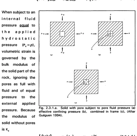
2.3.1 .a. Solid subjected to hydrostatic pressure
and internal pore fluid pressure. 34
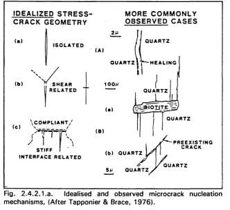
2 .4 .2 .1 .a. Geometries th a t cause cracking. 38
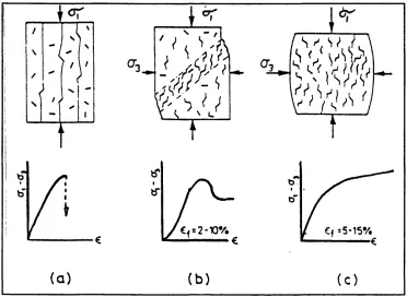
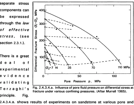
2 .4 .3 .1 .a. Sketch of Macroscopically brittle deformation. 41 2.4.3.4.a. Illustration of effective pressure law on sandstone. 44 2 .4 .3 .4.b. Illustration of concept of dilatancy hardening. 45 2 .4 .3 .5 .a. Illustration of brittle/Ductile transition (macroscopic). 46 2 .5 .2 .a. Coulomb Failure criterion illustrated by Mohr circle. 49
2.5.2.b. Coulomb criterion in principle stress space. 49
2.5.2.C. Mohr failure envelop. 49
2 .5 .3 .a. Tw o dimensional representations of G riffith criterion. 51
2 .5 .5 .a. Modes of fracture mechanics. 54
2.5.5.b. R-curve development of crack grow th. 55
2 .5 .6 .a. Schematic Diagram of sub-critical stress
corrosion cracking velocity/K curve. 57
2 .6 .2 .a. Illustrates crack grow th around a pre-existing flaw . 59 2.6.2.b. Photograph of wing crack interaction and bridge
form ation in PMMT plates. 61
2.6.2.C. Effect of interaction between collinear cracks
on the stress intensity factor, pseudo-traction solution. 62 2.6.2.d. A ffe ct of interaction between an array of collinear
cracks on the stress intensity factor of penny shaped
cracks in a local tensile stress. 62
2.6.2.e. Initial damage surface and failure surface fo r
W esterly Granite. 64
2 .7 .2 .1 .a. Acoustic emission event locations leading to faulting. 67 2.7.2.1 .b. Dependence of crack grow th rate & AE on humidity. 69
2.7.2.1 .c. Change in AE amplitude and frequency during
failure of sandstone. 70
2 .7 .2 .2 .b. Variations in crack density during triaxial deformation. 73 2 .7 .2 .3 .a. Opening of a throat, and increasing aspect ratio. 75 2 .7 .2 .3 .b. Changing aspect ratio for deformation at
different confining pressures. 76
2.7.2.4.a. Permeability reduction w ith increasing confining pressure. 77 2.7 .2 .4 .b . Permeability reduction w ith varying pore fluid pressure
and effective confining pressure. 78
2 .7 .3 .a. Schematic diagram representing the change in
physical properties during deformation. 80
3 .2 .a. Inflow and outflow of fluids about faulting. 85
4 .1 .a. Photograph of apparatus. 86
4.1 .b. Block diagram of the equipment. 87
4 .2 .2 .a. Diagram of balanced ram system. 90
4 .2 .5 .a. Strength of annealed copper jackets. 93
4 .2 .6 .a Specimen strain rate variation w ith deformation. 95 4 .3 .2 .a. Schematic diagram of original thermo-couple
wiring system, w ith o u t m onitoring or switching system. 98 4.3.2.b. Effect of temperature on limestone deformation as seen
by P-wave velocity measurements. 99
4.3.2.C. Example of smooth stress/strain curve at 300“C 100
4.3.2.d. Schematic diagram of new w iring/sw itching arrangement. 101 4.3.2.e. Frequency/amplitude graph.
showing the spikes due to furnace noise. 102
4 .3 .3 .a. Upper, lower and rock temperature for 0 to 400“C,
under zero confining pressure. 103
4 .3 .3 .b. Graph of Upper, lower and rock temperature
for 0 to 150“C, under lOOMPa confining pressure. 104
4 .4 .3 .2 .a. Specific volume of water under various pressures. 108 4 .4 .3 .2 .b. Calibration results. Water pressure against volume
for a variety of Upstream Reservoir Volumes. 108
4 .4 .5 .1 .a. Photograph of intensifier unit. 110
4.4.5.1 .b. Photograph of close coupled Pp tubing system. I l l 4.4.5.1 .c. Photograph of head block and 1/8^*’ tubing. 113
4 .4 .5 .2.C. Redesigned pore fluid upper ram. 116 4 .4 .5 .2.d. Diagram of redesigned ram/piston connector piece. 115 4 .4 .5 .3 .a. Photograph of pore fluid ram testing device. 118 4 .4 .6 .a. Effect of URV on pore fluid pressure change. 119 4.5.1 a. Mechanisms associated w ith acoustic emissions. 120
4.5.1 .b. Acoustic emission event. 121
4 .5.2.2.a. Cross-section of piston and ram ends. 123
4 .5 .2 .3 .a. Amplitude spectrum of P-wave form through aluminium. 124 4 .5 .2 .5 .a. 6-value calculated from different lower thresholds. 126 4 .5 .4 .a. Schematic diagram of acoustic emission
source characterisation. 130
5.2.1.1 .a. Photograph of the ram and copper jacketing system. 140 5 .3 .1 .a. Results from unsaturated sample under drained conditions. 149 5 .3 .3 .a. Results fully saturated sample under drained conditions. 151 6.1.3.1 .a. Typical drained stress/strain curve fo r Darley
Dale sandstone under different confining pressures. 155 6 .1 .3 .2 .a. Fracture stress and stress drop against confining
pressure for Penmaenmawr microgranodiorite. 156
6 .1 .3 .3 .a. Differential Thermal Analysis of Gypsum. 158
6.2.1 .a. Deformation behaviour of sandstone w ith different
added water volumes. 159
6.2.1 .b. Undrained deformation behaviour under different
confining pressure and fluid added. 160
6 .2 .1.e. Comparison of drained and undrained conditions on
deformation of sandstone. 161
6.2.1 .d. Drained and Undrained experiments on Darley Dale
sandstone monitoring pore fluid pressure/volume. 161 6 .2 .4 .1 .a. Drained & undrained results, Cp' = 20MPa on sandstone. 164 6.2.4.1 .b. Drained & undrained results, Cp' = 75MPa on sandstone 166
6 .2 .4 .1 .c. Drained & undrained results, Cp' = i25M P a on sandstone 168
6 .2 .4 .2 .a. Variations in URV on undrained deformation,
Cp'= 20MPa, sandstone. 169
6 .2 .4 .2 .b. Variations in URV on undrained deformation,
Cp' = 75MPa, sandstone. 171
Cp' = 125MPa, sandstone. 171 6 .2 .5 .a. Deviatoric stress/mean stress fo r four undrained results
a tC p ' = 20MPa. 175
6.2.5.b. Deviatoric stress/normalised mean, stress for four
undrained results at Cp' = 20MPa. 176
6.2.5.C. Pore fluid pressure rise under various URV's & Dev. stress. 177 6.2.5.d. Pore fluid pressure rise under various URV's & Mean stress.177 6.2.5.e. Two-D representation of pore fluid pressure surface
under increasing deviatoric and mean stress. 178
6 .2 .5 .f. Three-D surface of fig. 6.2.5.e. 179
6.2.5.g. Comparison of experimental and calculated pore fluid
pressure rise. 179
6.3.1.1 a. Four typical drained compaction hydrostats. 183
6.3.1.1 .b. Determination of critical crushing pressure in hydrostatic
compaction tests from Zhang et al. (1990). 183
6.3.3.1 a. Drained hydrostatic tests on steel samples (calibration). 188 6 .3 .3 .2 .a. Drained hydrostatic tests on microgranodiorite. 189 6 .3 .3 .3 .a. Tw o (of four) drained hydrostatic tests
on Darley Dale sandstone. 191
6.3.3.3.b. Tw o (of four) drained hydrostatic tests
on Darley Dale sandstone. 192
6.3.3.3.C. AE results form suite of drained hydrostatic tests
Darley Dale sandstone. 192
6 .3.3.3 d. Examination of gradient of Pvol/time curve for drained
hydrostatic tests on sandstone. 193
6.3.3.3.e. As 6.3.3.3.d., for tw o further drained hydrostatic results. 194 6 .3 .3 .4 .a. Undrained hydrostatic compaction results on
Darley Dale sandstone. 195
6.3.4.1 .a. Skempton's B co efficient from undrained
hydrostatic results. 197
6.3.4.1 .b. P- & S- wave velocity results from drained hydrostatic
tests on Darley Dale sandstone. 199
6.3.4.1 .e Extrapolation of drained hydrostatic com paction data
from Darley Dale sandstone. 201
6.3.4.1 .f. Smoothed B,obs.) and Bj^heorti) for undrained hydrostatic
compaction tests on Darley Dale sandstone. 204
6 .3 .4 .1 .g. As 6.3.4.l.g ., including B,çorr.,- 206
6 .3 .4 .2 .a. Effective confining pressure co efficient (alpha) for
Ks = 27GPa & 15GPa. 208
6 .3 .4 .2 .b. Total, permanent and elastic compaction of Darley Dale
sandstone, and calculated pore volume loss (6v) data. 209 6 .3 .4 .2 .c. Variation in ôv w ith B correction factor and K,. 210 6 .3 .4 .2 .d. Comparison of B co efficients for different K, values. 211 6 .4 .2 .a. Full suite of triaxial deformation experiments. 218 6.4.3.1 a. Effect of increasing fluid pressure on
triaxial deformation. 219
6.4.3.1 .b. Adjusted pore fluid volume curve for chemical activity of
high pore pressure fluid. 221
6 .4 .3 .2 .a. Drained triaxial deformation of sandstone,
Cp' = 22 & 50MPa. 2 2 3
6 .4 .3 .2 .b. Drained triaxial deformation of sandstone,
Cp' = 75 & lOOMPa. 2 2 3
6.4.3.2.C. Drained triaxial deformation of sandstone,
Cp' = 150 & 200MPa. 2 2 4
6 .4 .3 .2 .d. Drained triaxial deformation of sandstone,
Cp' = 255 & SOOMPa. 2 2 4
6 .4 .3 .2 .e. Triaxial result Cp' = 20MPa, Adjusted pore fluid volume
curves using "p c a" and "m r a" method. 226
6 .4 .3 .2 . f Triaxial result Cp' = 50MPa, w ith adjusted pore
fluid volume. 226
6 .4 .3 .2 .g Triaxial result Cp' = 76MPa, w ith adjusted pore
fluid volume. 227
6 .4 .3 .2 .h Triaxial result Cp' = lOOMPa, w ith adjusted pore
fluid volume. 227
6.4.3.2.1 Triaxial result Cp' = i50MPa, w ith adjusted pore
fluid volume. 228
fluid volume. 228
6 . 4 . 3 . 2 .k. Compilation of figures 6 .4 .3 .2 .e, f, & g., PCA method only. 2 2 9
6 .4 .3 .2 .1. Compilation of figures 6.4.3.2.h, i, & j., PCA method only. 230 6 .4 .3 .3 .a. Five triaxial deformation results showing cycling of
differential axial stress. 232
6 .4 .3 .3 .b. Last (e) curve of 6.4.3.3.a., expanded. 233 6 .4 .3 .4 .a. Drained and undrained triaxial deformation data in 3-D
space of effective mean stress, deviatoric stress, and
pore volume. 235
6 .4.3.4.b. View A of fig. 6.4.3.4.a., effect of effective mean
stress axis on pore volume, (drained and undrained). 236 6.4.3.4.C. 3-D plot of drained data only, effective mean stress,
deviatoric stress, and pore volume. 237
6.4.3.4.d. View B of fig. 6.4.3.4.C., effect of deviatoric stress only. 238 6.4.3.4.e. View D. of 6.4.3.4.C., shows increase in effective mean
stress and deviatoric stress w ith increase in differential
axial load. 238
6 .4 .3 .4 .f. View C of 6.4.3.4.C., showing effect of effective mean
stress on deformation. 239
6 .4.3.4.g. 3-D plot of undrained data, effective mean stress,
deviatoric stress and pore volume. 239
6.4.3.4.h. View B of fig. 6.4.3.4.g., showing effect of deviatoric
stress alone. 240
6.5.1 .a. Saturation vapour line for water. 245
6.5.1 b. Specific volume of water, T=0^250“C,
variety of pressures. 246
6 .5 .1.e. Specific volume of water, T=250-»450"C,
variety of pressures. 246
6 .5 .1 .2 .a. Effect of temperature on deformation of
Penmaenmawr microgranodiorite. 248
6.5.3.1 a. Effect of fluid under different pressures and temperatures (different mechanical properties) on undrained deformation
Darley Dale sandstone. 250
6.5.3.1 .c. Effect of temperature on drained triaxial deformation
of sandstone, T=20-»200“C, Cp'=45MPa. 255
6.5.4.1 .d. Suite of drained triaxial deformation results displaying
effect of temperature on strain hardening/softening. 255 6 .5 .4 .2 .a. Drained and undrained triaxial deformation of
microgranodiorite. 257
6 .5 .4 .2 .b . Effect of temperature on drained triaxial deformation of
microgranodiorite, T=20-*400°C. 259
6.6.1 a. Sigmoidal curve of drained dehydration of gypsum. 264 6.6.1 .b. Dependence of drained dehydration on pore fluid pressure
and confining pressure. 265
6 .6 .I.e . Sigmoidal curve of undrained dehydration of gypsum. 266
6.6.3.1 .a. Results of drained dehydration of gypsum. 267
6.6.3.1 b. Effect of effective confining pressure and pore fluid
pressure on reaction rate. 269
6 .6 .3 .2 .a. Undrained triaxial deformation of dehydrating gypsum. 271
A .I. Calibration of load cell. 281
B.a. Redesigned upper ram for P- & S- waves velocity and
pore fluid volumometry measurements. 285
Tables.
Tables. Page.
4 .4 .3 .2 .a. Increase in cross-sectional area for different hp
tubes under effect of pressure. 109
6 .3 .1 .2 .a. Results from previous w ork on Skempton's B co efficient. 184
Glossary
3o Initial crack radius.
a Effective stress coefficient.
a Ratio (c//?) - initial crack lenght/grain radius.
AE Acoustic emissions.
B Skempton's B co efficient,
c Microcrack length.
Cp Confining pressure, ( = Pc).
Cp' Effective confining pressure, ( = Pc'). C Bulk com pressibility of rock, ( = 1/K). C^ Bulk compressibility of water, ( = 1/Kf).
C, Bulk compressibility of solid part of rock, ( = 1/KJ. dj Initial spacing between interacting cracks.
D Damage parameter in cracked solid.
D Fractal dimension for crack size analysis.
€ Bulk strain.
6kk Volumetric strain in a given orientation (kk). 6kk Bulk strainin a given orientation (kk).
(Je^k Increment of bulk strain in a given orientation (kk).
€ Dimensionless crack density parameter.
E Young's modulus.
f Emprically derived scaling constant (eq. 2.6.2.b.).
F Proportionality factor between crack driving force from crack interaction and deviatoric stress.
G Shear modulus of porous rock determined in the absence of pore fluid.
GPa Giga Pascal.
hp High pressure.
K Bulk modulus of rock w ith unfilled pores - the rock "skeleton", ( = 1/C).
Kg Bulk modulus of solid part of rock, ( = 1/0,).
Ku Effective bulk modulus of rock under undrained regime. Kf Bulk modulus of fluid, ( = 1/CJ.
Crack tip stress intensity factor (m = l, II, or III)
Critical crack tip stress intensity factor for crack propagation.
K Rock permeability.
L Normalised crack extension for propagating cracks.
LVDT Linearly Variable Differential Transducer.
MPa Megapascals.
PC Personal Computer.
Pp Pore fluid pressure, (= p ).
p Pore fluid pressure, ( = Pp)
pu Change in pore fluid pressure under undrained conditions due to applied stress.
6p Pore fluid pressure change due to stress under undrained regime.
P^ Pore fluid volume.
Pc Confining pressure, ( = Cp).
Pc' Effective confining pressure, ( = Cp').
p " Pore collapse pressure.
0 Rock porosity.
Ô0 Change in rock porosity.
Q Seismic quality factor.
S Shear stress.
R Elastic strain constant - measure of change in w ater content for a change in pore fluid pressure.
R Grain radius.
SSJ Increment of volum etric strain.
ÔV Change in pore volume of rock under drained conditions under
stress.
Maximum principle stress. Intermediate principle stress.
O2 Intermediate principle stress.
Mean stress.
Effective mean stress.
(7kk Hydrostatic stress.
// Co efficient of friction.
URV Upstream Reservoir Volume.
V Poisson s ratio.
Vy Poisson s ratio for a porous rock in undrained regime.
Vp Pressure wave velocity.
Vs Shear wave velocity.
Acknowledgements
I w ould like to thank a number of people in connection w ith this thesis and w ith m y time spent at University College London.
Firstly I would like to thank Stan Murrell for his scientific advice and guidance, and unmatched enthusiasm for this w ork; Philip Meredith for his tim e and effort spent on the details of this thesis, w ith reviewing conference papers, and w ith securing overseas conference visits; and Peter Sammonds for assistance w ith equipment development in the early stages of this project.
Acknowledgem ent goes out to the crew o f Hut 18 who have kept me sane through some of the more frustrating moments of the last few years. This includes, Dave Raistrick, John Bowles, Neil Hughes, and Anita Odedra. Also w o rthy of the same thanks is the senate house luncheon group, Dave, Anita, Greg Fookes, and Gerald Roberts. Extra thanks to Gerald for tim e spent explaining the details of structural geology.
Thanks also for scientific advice freely forthcom ing from all those in the Rock and Ice Physics lab.; to Tobi for yet more photo's of the equipment; to John and Neil and Steve Boon for equipment modification, developments, machining and general tinkering; and to Henry Tillotson for his tim e creating the 3-D images used in this thesis.
Finally, a special thanks to Karen de Rochemont. Karen has been patient and supporting in every sense throughout the Ph.D., especially through the last hot summer of 1995. This thesis is dedicated to Karen.
CHAPTER 1.
INTRODUCTION.
1.1. Introduction and Objectives of the Study.
The behaviour of crustal rocks as cracked porous fluid filled media under the influence of imposed lithostatic and fluid stress conditions is of vital importance to industries and researchers concerned w ith understanding and controlling rock deformation in fields such as hydrocarbon extraction, mining, civil engineering, radioactive waste storage, and understanding earthquake nucléation & crustal evolution processes. Furthering the understanding of the mechanisms responsible for brittle deformation is a goal of researchers around the w orld, and this project makes a contribution to th a t goal through improved experimental capabilities and examination of dilatancy and compaction mechanisms during deformation under crustal stress and temperature conditions.
Polycrystalline rock is comprised of a matrix of mineral particles, spherical pores, and microcracks. It is the presence of voids in rocks, their effect on local stress concentration due to far field stresses, and the subsequent nucléation, grow th and eventual interaction of microcracks, which is responsible for brittle rock deformation. In the laboratory, specimens of rock can be subjected to conditions of confining pressure, pore fluid pressure, and temperature in an attem pt to reproduce crustal conditions and study these complex micro-mechanisms. Imposing full triaxial crustal conditions allows the material properties of the rock to be analysed in a natural sub-surface state. Scaling problems often encountered w ith rock strength analyses (laboratory specimen to crustal scale) are less significant w ith material property analysis, and so the results obtained are of direct relevance to the earth science industries mentioned above.
in rock under undrained conditions concerning the growth of microcracks (pore volume increase); crack growth reduces pore fluid pressure, increases effective stress and hence changes the stresses upon which the mechanisms of m icrocrack growth depend. Combined w ith other factors also influential in controlling the deformation process, (i.e. temperature, rock permeability, mineral fracture toughness, fluid flo w conditions - i.e. drained or undrained), the mechanisms of fluid/rock interactions are complex.
In order to conduct the experimental programme, the development of equipment capable of controlling and monitoring fluid pressure and volume changes in deforming rock specimens was necessary (section 1.3.). This has allowed a comprehensive experimental study to be conducted to elucidate aspects of fluid/rock interactions in the deformation process, and to examine changing pore and crack volume (due to axial deviatoric stress (<7i-a^, hereafter referred to simply as deviatoric stress), and effective mean stress), during deformation under a range of crustal stress and temperature conditions. The results are analysed and interpreted in terms of established poro-elasticity theory and the behaviour of a cracked porous solid in which cracks/pores may change both elastically and inelastically. Results are presented in detail in chapter 6 and general conclusions are contained in chapter 7.
1.2. Experimental Programme.
Throughout the study 199 separate experiments were conducted, logged and analysed. Of those, « 1 4 0 yielded sufficiently complete data sets to be of use.
The range of experiments conducted address a variety of fluid/rock deformation problems. These are described below.
► A comprehensive series of drained and undrained triaxial deformation experiments on Darley Dale sandstone up to confining pressures of
sandstone. Analysis of mean stress, deviatoric stress, and pore fluid volume for the suite of experiments has been undertaken to examine deviatoric and mean stress induced changes in pore volume through mechanics of dilatancy and compaction.
► Extension of the above programme to investigate the effect of temperatures of up to 400"c on the deformation of Darley Dale sandstone and Penmaenmawr microgranodiorite under both drained and undrained conditions.
► An analysis of drained and undrained hydrostatic compaction on both Darley Dale sandstone and Penmaenmawr microgranodiorite under a variety of stressing rates and cyclical peak stresses up to 450MPa. This isolates the mean stress induced compaction component of pore fluid volume loss for analysis independently and in comparison w ith triaxial deformation results.
► A suite of undrained triaxial deformation experiments varying the fluid system volume outside the vessel (necessary to m onitor changing fluid pressure, called the Upstream Reservoir Volume - DRV). The effect of a variety of URV's on pore fluid pressure change is observed, and results allow prediction of pore fluid pressure changes under zero URV to be attempted.
► A suite of dehydration experiments on gypsum monitoring the increase in fluid volume. Factors affecting dehydration rates and triaxial deformation of dehydrating gypsum are investigated.
1.3. Equipment Development.
The extreme crustal conditions possible using the high pressure gas medium rock deformation cell at the Rock and Ice Physics Laboratory are i400M P a
emissions and either, (i) P- and S wave velocity or, (ii) pore fluid volum om etry (pore fluid intensifier sited remotely from pressure vessel). For the proper investigation of dilatancy and compaction under undrained triaxial stress conditions the dose coupling of the pore fluid intensifier w ith the deformation cell was vital. The integration of previously independent logging systems, a redesigned pore fluid upper ram, a ram-leak testing device, and extensive m odifications to the pore fluid supply and pressure transducer arrangement was an integral part of this equipment development programme. The existing high temperature furnace was also recommissioned for the study. The overall equipment development work demanded extensive calibration testing programmes. Prior to the experimental programme, modifications were also carried out to the manufacturing technique of the so ft copper jackets (required to protect rock specimens from confining pressure gas), to computer logging software, and to the i400M P a confining pressure pump. The present study used the equipment to limits of 450MPa confining pressure, 400 “ c temperature,
and 350MPa pore fluid pressure. Details of the equipment development
programme are contained in chapter 4.
1.4. Arrangement of the Thesis.
The thesis is divided into six further chapters follow ing this introduction. They discuss in turn;
(i) the micro-mechanisms by w hich dry and fluid filled porous rocks deform and theories describing rock deformation,
(ii) the effect of fluids in the crust,
(iii) equipment used and m odifications undertaken during the study, (iv) techniques developed in the study,
(v) the experimental programme undertaken, results, discussion and conclusions, and finally,
(vi) conclusions and comments on the results of the study, and future w ork possibilities.
Chapter 2 form s the background to rock deformation studies. It begins by describing the microstructure of polycrystalline rocks. Rock, considered as a matrix of mineral grains, spherical pores, and microcracks, is then discussed in terms of poro-elasticity theory. Deformation mechanisms (for rocks w ith and w ith o u t fluids) based on empirical data is then considered, and the theories of brittle crack grow th in rock is reviewed. Recent continuum damage models are then reviewed, and the chapter concludes w ith holistic view of porous rock deformation and the evolution of crack damage as monitored by measurement of changing rock physical properties.
Chapter 3 briefly describes the role of fluids in the crust. Fluid sources are considered along w ith fluid driving forces. The effect of fluid both mechanically and chemically on the behaviour o f rocks under crustal pressure and temperature conditions is discussed. This chapter attempts to connect problems of fluid in the crust w ith the experimental rock physics research.
Chapter 4 describes the equipment used in the study. Calibration of equipment, and modifications to the pore fluid pressure intensifier, to the high temperature furnace, and to the logging system are described. Acoustic emissions technology and techniques are discussed, and new component design and commissioning is presented.
Chapter 5 describes specimen preparation techniques, experimental procedures, and research techniques developed throughout the study.
Chapter 6 describes, discusses and analyses the results. It is divided into 6 discrete sub-sections, each of which deals w ith a certain aspect of rock deformation as monitored by pore volumometry. Each sub-section is self contained w ith a relevant review section, discussion, analysis, and a note on pertinent future w ork possibilities. Section 6.1.1. describes these sub-sections in more detail.
CHAPTER 2.
MICROSTRUCTURE OF ROCKS (CRACKS AND
PORES). MICRO-MECHANiSMS OF FAILURE,
FLUID/ROCK INTERACTIONS. AND DAMAGE
MECHANICS - A REVIEW.
2.1.
Introduction.
The deformation and failure of rocks under stress is complex and depends on many environmental factors such as, confining pressure, pore fluid pressure, temperature, applied differential stress, and rate of stress change. Internally, the porosity and pore structure of the rock affects pore fluid pressure change during deformation and hence alters the deformation characteristics of the rock through the law of effective stress. W hilst much is understood about the response of porous materials to internal fluid pressure and external confining pressure, (presented here), much remains outstanding and the need for experimentation continues.
In order to assist the understanding of this complex interplay of mechanisms. Chapter 2 addresses the physical processes of deformation leading up to rock failure -rock compaction, microcrack nucléation, crack extension & linkage, and coalescence of microcracks. Theoretical models based on these concepts, from the earliest to the most recent, are reviewed, and the application of some of these processes w ith respect to earthquake faulting and fluid flo w in the crust are reported. Finally, experimental methods used in this study and elsewhere, to examine fully these processes during deformation are presented.
2.2. Micro-Structure of Rocks.
of a rock has a large effect on pore and crack micro-structures, and hence on
the gross behaviour of rock under stress.
Igneous rock crystallisation occurs either on the surface of the Earth (volcanic igneous) or beneath the surface (plutonic igneous). Different cooling temperatures and durations control crystal grain size - a smaller grain size resulting from rapid cooling. Because igneous rocks crystallise in-situ, a tight structure w ithout pores generally results (the exception is rock containing dissolved gases - e.g. basaltic magmas - w hich generate pores from enclosed bubbles). The tig h t matrix created causes porosity to be as low as 0.1% which is often comprised of fu lly or nearly closed /nfe/'granular cracks. Fractures in igneous rocks generally occur subsequent to rock form ation, and although they are often of low aspect ratio (minimum dimension < < maximum dimension), their interconnecting nature can allow a permeability th a t is surprisingly high for such a low porosity.
Sedimentary rocks are most commonly a collection of previously weathered, eroded and transported (rounded) particles, and the energy of the depositional
environment (water or wind blow) dictates the grading of the rock particles (grains). A high energy environment causes only one particle size to be
deposited at a given location, resulting in a w eii graded rock (high porosity -0.4-0.45), whilst a low energy environment allows many particle sizes to be
deposited at one location, resulting in a poorly graded rock (lower porosity). Initial porosity is controlled by three main factors, (i) grain size, through enhanced gravity assisted settlement of the larger grains - smaller grain sized
sediments do not compact until pressure assisted, (ii) grain shape, through frictional resistance to gravitational settlement from rough surfaced grains,
and, (iii) grading, poorly graded sediments allow smaller grains to fit between the larger grains, therefore reducing porosity without decreasing overall
packing of the large grains.
► Consolidation is the rotation and rearrangement of particles reducing the void ratio and expelling interstitial fluid. The amount of consolidation possible is limited by the grain size; larger grains consolidate more up to a minimum porosity of *0.4. For grains <iOO/fm, minimum porosity increases sharply, (Guéguen & Palciauskas 1994) consolidation is less im portant in sandstones than in other sediments such as shales, due to the high grain friction and large particle size of sandstone.
► Compaction is the principle porosity reduction mechanism, and involves the deformation of grains through physical damage and chemical alteration; a mixture of different particles under compressive stress and in a potentially foreign pore fluid creates an environment in disequilibrium which is then the subject of grain fracturing and mineral dissolution/precipitation. The latter process moves mass locally and/or great distances, and is the cause of siliceous and carbonaceous grain cements in sandstones.
► Diagenesis is a form of low-grade metamorphism involving the grow th of new minerals from fluids leading to the cementation of grains.
The most significant effect of tectonic stressing in the crust is the development of microcracks w ithin rock. Microcracks are openings w ith tw o dimensions much larger than the third. They are categorised in groups dependent upon their location and path.
Intra-granular Cracks occur w ithin grains. They are slot like cavities w ith blunted ends, often tortuous, w ith an aspect ratio of 10'^ to 10'^. Crack aperture is as low as i/m i. They are often known as cleavage cracks, w hich are cracks confined to a particular plane of the crystal lattice, extremely sharp, and parallel except where they merge w ith uncracked material.
Cracks can have a significant effect on rock mechanical and physical properties - e.g. elastic and inelastic strain under load, peak stress, permeability, elastic wave velocity. Crack population orientations are often anisotropic, in response to an anisotropic stress field, and when considering certain physical properties such as elasticity, permeability and electrical conductivity, values are often directional and scale dependent (within a certain range). For this reason, effective properties are often used to describe the mean macroscopic properties of rock fo r three directions, w h ilst mini- and microscopic variations are neglected, (Paterson 1978). The internal surfaces of cracks and pores also strongly affect physical behaviour, i.e. surface roughness is particularly important.
The importance of surface roughness concerns the ability of a crack to open and close elastically w ith having to crush mismatched asperities and debris; this affects porosity loss under hydrostatic load. Roughness can be characterised by the distribution of asperity maxima. This can be characterised by the use of fractals (Main et al, 1990).
The relationship between rock microstructure and rock physical properties is complex, and requires knowledge of the shape, structure and inter connectivity of the pores and cracks. This inform ation has to be inferred indirectly from measurements such as porosity, specific surface area, electrical conductivity, and permeability. These physical properties can be measured during deformation, (section 2 .7 .).
In describing the behaviour of porous media under the e ffect of stress, elasticity must be generalised to poro-elasticity, and when considering the effect of a fluid phase on porous media the question of drained or undrained
conditions must be considered; i.e. whether fluid pressure or fluid mass is the independent variable, (section 2.4.S.4.). Explanation of the effective stress law is necessary before further analysis.
2 .3 .1 .
Effective Stress Law for Undrained Hydrostatic
Compression.
Considering fluid in the pores and cracks of a rock w ith fluid mass (m), and fluid density (f), and fu lly saturated when fluid volume equals pore volume
(v = cp); compressibility of the fluid component of the tw o phase (fluid filled)
rock system will depend upon the bulk modulus of the fluid (Kf), and pore fluid pressure (p). The effective confining pressure (Pg') is defined as;
P / = Pc - a p (2 .3 .1 .a .)
Where p is the pore fluid pressure, and a is a constitutive relation of poro-elasticity - the effective stress co efficient. When a = 1, the effective pressure is equal to the difference between the confining pressure and the pore fluid pressure. Otherwise a is found by;
a = 1 - K/K, (2 .3 .1 .b.)
where K, is the bulk modulus of the solid part of the rock, and K is the bulk modulus of rock w ith pores - the rock "skeleton" or "fram e". This equation is derived from an analysis proposed by Nur & Byerlee (1971), presented below.
{<ÎV/V},p^pi = (6kk),pp.p, = - (Pp-p)/K (2 .3 .I.C .)
When subject to an i n t e r n a l f l u i d pressure equal to t h e a p p l i e d h y d r o s t a t i c pressure (Pc=p), volum etric strain is governed by the bulk modulus of the solid part of the rock, ignoring the pores as full w ith fluid and of equal pressure to the e xternal applied
Fig. 2 .3.1.a. Solid with pore subject to pore fluid pressure (a) pressure. Because effective confining pressure (b), combined in frame (c), (After
the modulus of Guéguen 1994).
solid without pores is K.
{ 6 V /V } (p g = p ) — (6kk)(pc=p) — “ p /K s (2.3.1.d.)
As linear theory is used, the tw o conditions can be superimposed when different external and internal pressures exist, such that;
{ 6 v / v } , - - (Pp - p)/K - p/K , (2.3.1.e.)
or;
fkk = - (Pp-Op)/K = - Pp'/K, (2 .3 .1 .f.)
For porous rocks when K,> >K, and a-K).9. However, fo r rocks of low porosity where K-»Kg, a can approach 0.6. For Darley Dale sandstone a =
0.75-*0.85 dependent on the effective confining pressure.
2 .3 .2 .
Poro-eiastic Constants for Drained and Undrained
Hydrostatic Deformation.
For drained conditions, the fluid mass in the rock remains constant w h ilst its volume varies w ith deformation. Stress/strain relations are the same as in ordinary elasticity and the law of effective stress applies. Under hydrostatic compression the strain e is proportional to the stress a by;
6= ( / / K (2.3.2.a.)
Where o ' is the effective hydrostatic stress.
Under undrained conditions the value of pore fluid pressure change is determined by the internal deformation of the medium. In this instant
effective constants (denoted by subscript u), are used to describe the behaviour of the rock/fiuid system under stress. Such th a t K is replaced by
K„ - the bulk modulus due to the combined fluid and solid phases, hence;
e = a/K„ (2.3.2.b.)
The concept of effective pressure is of little use because the pore fluid pressure is unknown and changes in response to volum etric strain of the rock. The change in pore fluid pressure (6p), is a function of the bulk modulus of the fluid/rock system K^, the bulk modulus of the solid rock m atrix K, and a,
by;
= -{ (K y - K ) / t / } . 6 (2.3.2.C .)
Combining 2 .3 .2 .a. and b., introducing an independent co efficient B called the
B = 1 /K „.{(K „ - K )/o } (2.3.2.d.)
I.e., the fluid pressure increase can be expressed in terms of an increase in hydrostatic confining pressure for undrained conditions, and the Skempton co efficient.
6p = -B.(o) (2.3.2.e.)
Linear poro-elasticity, therefore depends on the independent rock constants; K, K„, and a, (with p - the shear modulus - used in shear stress analysis, although p^=p).
K can be obtained through drained (or dry) hydrostatic experiment, and K„ obtained through hydrostatic r/ndrained experiments measuring the pore fluid pressure generated. is a function of K^, K, and 0. W ithout explicitly deriving K„, it can be related to K when under the special case of P,. = p . Under these conditions the rock is subject to a homogenous pressure, "appears” homogeneous and w ithout pores, and of bulk modulus K,. Based on equation 2.3.l.g ., after rearranging for K^;
K„ = K + o ^ /[(0 /K ,) + ((a - 0 )/K „)I (2.3.2.f.)
It should be noted that physically, is dependent on pore shape although a term accounting for this does not appear in the above relation.
In the drained case, the fluid mass w ill change during hydrostatic stressing as
or
a function^bulk strain of the rock and pore fluid pressure. From an internal energy analysis of the rock under infinitesimal strains, (Guéguen 1994), the change in fluid mass can be expressed as;
Sm = m - rrio = a .n .e 4- Ap (2.3.2.g.)
change is found by considering the change in density {6 n ) as a function of
p, where ô m = n . ô v + v.SD, {ôv is the change in fluid volume). When fluid volume (v) equals porosity {0), the equation for change in fluid volume w ith bulk moduli of rock is found;
6 y = a .fk k + [(û ^ /(K „ -K )) - { 0 / K f ) ] . p (2 .3 .2 .h .)
K„ can differ substantially dependent upon the relative values of K^. If K,-»0, then w hilst if K^-^infinity, then K4-((o^.Kg)/(a-0)). The practical analogy is when rock is saturated w ith a gas compared w ith a liquid. Theory predicts a lower for a gas, and this is im portant fo r oil and gas industries.
The variations of B between i and 0 concern these tw o cases; when B->1,
K-*0, i.e. for a porous, unconsolidated medium, and when B-K), K-^K^ under circumstances of a very compressible fluid.
2.4. Deformation Mechanisms and Brittle Behaviour.
2 .4 .1 .
Introduction
Rocks deform by a variety of different micro-mechanisms. Environmental conditions are prominent factors in dictating w hich mechanism is prevalent at any time. Deformation behaviour in rocks as a consequence of these mechanisms can be broadly divided into macroscopically brittle, (faulting failure), macroscopically ductile flo w (cataclastic flow ), and ductile deformation. The micro-mechanisms operating during these different modes of deformation are outlined below. This section reviews work which describes the brittle microscopic and macroscopic deformation of rock under crustal conditions.
2 .4 .2 .
Deformation Mechanisms.
Brittle crack initiation and grow th in poly-crystalline material results from local tensile stress exceeding local tensile strength. This can be mechanically or therm ally induced. The multiphase nature of rocks produces stress and strength heterogeneity even under a uniform macroscopic stress. Stress concentrations arise from crack tips and grain contacts geometries (which dictates the location, magnitude and orientation), w hich then leads to the initiation and propagation of cracks, (fig. 2.4.2.l.a.).
ID E A L IZ E D S T R E S S -CRA C K G EOM ETR Y
MORE C O M M O N L Y O B SER VED C A S E S
2H
Q U A R T Z I S O L A T E D
Q U A R T Z H E A L I N G
( b) S HE AR
R E L A T E D Q U A R T Z
Q U A R T Z \ C O M P L I A N T
P R E E X I S T I N G C R A C K S TI FF I
I NT E RF ACE R E L A T E D ( b) Q U A R T Z
Q U A R T Z Q U A R T Z
Fig. 2.4.2.1 .a. Idealised and observed microcrack nucléation mechanisms, (After Tapponier & Brace, 1976).
► Movement between tw in lamellae generates stress when in contact w ith grain boundaries and causes crack grow th at the tw inning site (Olsson & Peng 1976).
► Microcracks develop normal to kink band boundaries as a result of deformation accommodation problems either side of a kink band, (Carter & Kirby 1978).
► Point and line contacts at grain boundaries cause stress concentrations and usually initiate mode I extensional cracking.
► Stress concentrations around cavities, dependent on crack geometry and orientation, initiate cracking.
► Stiffness mismatch between adjacent minerals under a common stress field can initiate cracking due to differential strain and consequent stress concentration (Dey & Wang 1981). Calculations have shown tensile stresses of the order of lOOMPa are possible.
► Grain rotations and translations can occur under deviatoric stress causing intergranuiar cracks. The interface strength of quartz and feldspar bonds has been found to be under lOMPa, (Savanick & Johnson 1974). In crystalline rocks rotations and translations are found to be more d ifficu lt because of tighter interlocking, although they can occur during cataclastic flow .
► Wing crack nucléation and growth at the tips of favourably inclined pre
existing flaws, (see fig. 2.7.2.a.).
2 .4 .2 .2 .
Ductile Mechanisms.
Ductile deformation is prevalent at elevated temperatures and low strain rates
and a brief synopsis of those mechanisms is presented below ; for a comprehensive review see Barber (1990).
► Dislocation Gliding. Dislocation in material arises from the migration of a flaw by transfer of atomic bonds. By this method the dislocation travels and causes material strain. Dislocation migration inevitably interacts w ith obstacles (grain boundaries, precipitates), and it is the rate w ith w hich the dislocation can overcome these obstacles that governs overall material creep.
► Diffusion Creep. This mechanism is predominant at high temperatures and low stresses and can be found in conjunction w ith Grain Boundary Slippage (GBS). Deviatoric stress causes gradients in chemical potential giving rise to diffusive fluxes of vacancies and atoms. This allows grains to change shape and sliding to occur at grain boundaries. If creep occurs by this process w ith o u t opening intergranuiar cracks, material integrity is maintained.
► Grain Boundary Slippage. This often occurs in conjunction w ith diffusional creep, especially when the grain size is small. GBS is not self-sufficient because it produces excess material and voids which must be accommodated by other processes.
► Pressure Solution. This is the migration of solids by solution. Dissolution in regions of high pressure, followed by fluid migration and deposition in regions of lower pressure causing mass transfer and resulting in creep behaviour in the rock.
The combination of any or all of these processes causes fracture free strain in geological materials.
2 .4 .3 .1 .
Overview of Deformation Modes.
à r
(b)
Fig. 2.4.3.1 .a. Brittle failure modes under differential axial stress and increasing confining pressure, see text. (After Ashby and Hallam 1986).
The application of confining pressure on rock during deformation has the effect of increasing the ultimate strength o f the rock. A number of different deformation modes occur in the rock as the confining pressure is increases. These are briefly described below before a more detailed review in later sections. See fig 2.4.3.i.a .
► Under uniaxial compression (zero confining pressure) the rock fails by tensile crack grow th parallel to the axis of maximum principle stress, called slabbing or splitting.
fa u lt plane. Singular dilatant tensile crack grow th is inhibited by confining pressure.
► Higher confining pressure inhibits tensile crack grow th to the extent th a t the development of a shear band is inhibited This occurs when the shear strength becomes less than the frictional strength (Murrell 1965), and no stress drop occurs. Strain is accommodated throughout the specimen. This is cataclastic flo w - macroscopic ductility although internal mechanisms are brittle involving the nucléation but minimal extension of microcracks. Dilatancy and strain hardening is reported to occur throughout deformation, (Jones 1988).
► Finally, when confining pressure and temperature are sufficiently high dilatancy and its associated mechanisms are largely inhibited, and non- d ila ta n t m e c h a n is m s s u c h as c r y s ta l p la s t ic it y and dissolution/precipitation dominates, (Murrell 1990).
Peak strength is slightly strain rate dependent in the brittle
field; an increase in strain rate of tw o orders of magnitude causes a 10% increase in strength, although w ith the presence of fluid, dilatancy hardening
must be considered (section 2.4.3.4.). Elevated temperatures affect deformation through partial rock melting or high temperature em brittlem ent.
The latter is due to mineral phase changes releasing fluid and affecting the
effective confining pressure of the rock. A good overview of brittle deformation can be found in Paterson (1978).
2 .4 .3 .2 .
Effect of a Hydrostatic Stress.
and rearrangement. Kranz (1983) postulated th a t differential crystal compressibility should produce differential crystal strain, inducing cracking, and Todd (1973) found AE during hydrostatic loading of rock, although he
attributed it to grain crushing. In a hydrostatic loading study on sandstone, Zhang et al. (1990), found an inflection point on the stress/strain curve at a certain critical hydrostatic pressure signifying pore collapse (grain crushing). The mechanism suggested as responsible was Hertzian cracking at grain contacts. A fte r this point rock porosity fell rapidly under subsequent loading. This critical pressure was found to be inversely related to porosity and grain size, (see section 6.3.l.l.) .
2 .4 .3 .3 .
Effect of a Deviatoric Stress Field.
Under a macroscopic deviatoric stress field, a complex microscopic stress system occurs as a results of structural and mineralogical heterogeneities. Local crack tip stress intensities can be much higher in magnitude than the macroscopically applied stress field, and the principles of fracture mechanics apply for the consideration of crack grow th, (section 2 .5 .5 .). Observations
show th a t the realities of crack grow th deviate som ewhat from model idealisation, (Swan 1975): the vast m ajority of micro-cracks appear to be extensional mode I cracks - section 2 .5.5. although this may be because shear displacements (modes i i and III) are too minimal in magnitude to be noticed or preserved for post-deformation analysis.
2 .4 .3 .4 .
Effect of Pressurised Pore Fluids.
Fluids affect rocks both mechanically and chemically. The early theory o f
effective stress of Terzaghi, concerned the mechanical effect.