Development of Generalized Methodology for Root
Cause Failure Analysis for tubes of Coal based Boiler
Gagan Kumar Gupta
1, Dr. Somnath Chattopadhyaya
21
Research Scholar, Mechanical Engineering Department, Indian School of Mines, Dhanbad (India)
Deputy Manager, BPSCL (A Joint Venture Company of SAIL & DVC) Bokaro (India)
2
Associate Professor, Department of Mechanical Engineering,
Indian School of Mines, Dhanbad, (India)
ABSTRACT
The actual nature of failure could not be ascertained at the operating unit. Therefore, the need arises to
develop the complete methodology for investigating the root cause of failed pressure parts tubes. The present
paper presents the generalised methodology for failure investigation of superheater tube of coal based boiler
consisting of visual observation, identification of sampling locations, determination of bulk chemical
composition of base alloy, microstructural investigation using optical microscopy, explore the finer
structural details using scanning electron microscope (SEM), evaluation of hardness over samples obtained
from different locations, fractographic analysis of different failed locations, X-ray diffraction (XRD) study of
corrosion products adhered to inner surface and conclude the nature of failure. The present work provides
the strong data base for ascertaining the base cause of failure and key solution of Industrial boiler tube
failure related problems.
Keywords:
coal based boiler, corrosion, creep, fractographic analysis, SEM
I. INTRODUCTION
Boiler is a vital element in power plants with regards to running cost and performance. The boiler consists of
several subsystems like I.D. Fan, F.D. Fan, P.A. Fan, Ball Mill, R.C. Feeder (PA Fan, Ball Mill and R.C.
Feeder constitute one complete subsystem, Economizer, Super heater, Boiler drum, Water wall tubes and
High pressure valves. A major part of the power generating system’s operating costs is due to unplanned
system stoppages for unscheduled repair of the entire system or of components. Since failure cannot be
prevented entirely, it is important to minimize both its probability of occurrence and the impact of failures
when they do occur. Boiler tube failure is the prime reason of forced Outages at coal fired thermal power
plants. With ever increasing demand for electricity, it is very necessary for the power plants to generate
electricity without forced outages.
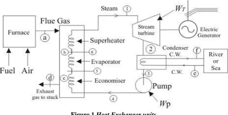
The basic components of the plants are steam generator {Steam generator is a complex integration of boiler
along-with accessories (furnace, super heater, re-heater, boiler, economizer & air pre-heater etc.) and various
auxiliaries such as pulveriser, burners, fans, stokers, dust collector and precipitators, ash-handling equipment
&chimney.}, steam turbine, steam condenser and feed water pump. Heat transfer to water in steam generator
Figure 1
Heat Exchanger units
Water is at first pre-heated sensibly in the economizer in liquid phase at a certain pressure from state 4 to
state 5 (refer to the diagram below) till it becomes a saturated liquid. It is then send to the evaporator, where
this saturated liquid is boiled associating a change of phase from 5 to 6 by absorbing the latent heat of
vaporization, at that particular pressure. Now this saturated vapour in state 6 is further heated in the
super-heater, to bring it to state 1, i.e. in gaseous or vapour form. For unit mass of fluid, the heat transfer equation
in the 3 types of heat ex-changers are given by,
QEconomiser = h5-h4
QEvaporator = h6-h5
QSuperheater = h1-h6
Out, of these 3 major heat ex-changer components, only the economizer operates with, zero fuel
consumption, and thus it is one of the most vital and economical equipment in a thermal power plant. Boiler
tube failure is the prime reason of forced Outages at coal fired thermal power plants. With ever increasing
demand for electricity, it is very necessary for the power plants to generate electricity without forced
outages. The optimization of each subsystem in relation to one another is imperative to make the system
profitable and viable for operation. Effectiveness of the power generating equipment is mainly influenced by
the availability, reliability and maintainability of the system, and its capability to perform as expected.
Reliability analysis techniques have been gradually accepted as standard tools for the planning and operation
of automatic and complex power generating. A major part of the power generating system’s operating costs
is due to unplanned system stoppages for unscheduled repair of the entire system or of components.
Therefore, preventive maintenance is widely considered an effective strategy for reducing the number of
system failures, thus lowering the overall maintenance cost. The primary goal of preventive maintenance is
to prevent the failure of equipment before it actually occurs. Preventive maintenance activities include
equipment checks, partial or complete overhauls at specified periods, oil changes, lubrication and so on
where it is required. From an economic point of view, high reliability is desirable to reduce the maintenance
costs of systems. Failure analysis has helped in identifying the critical and sensitive subsystems in the power
critical for improvement of equipment performance and ensuring that equipment is available for power
generation as per schedule. The main objective of any electric power generation system plants is to supply
the amount of energy demanded by the market and to comply with the regulatory requirements defined by
government laws. To attain the objective, one of the most important requirements for any power generation
system is to guarantee its technical reliability and availability.
Hence, a boiler generates steam via the optimized combustion of fuels (coal, gas & oil, etc.) consisting of
several components of rotary equipment and pressure parts. The efficient and trouble-free operation of a
boiler is difficult to maintain because the characteristics of input fuel vary over time. Deteriorated
performance and repetitive failures of pressure parts of boiler is a very common issue. Brooks et. al. have
stated that Metallurgical failure analysis is vitally important to materials, metallurgical, and mechanical
engineers responsible for the evaluation of faulty machinery and structural components. Dennies has
presented a proven systematic approach and template to advance a failure investigation, including a
discussion of the methodology required, organizational tools, and a review of failure investigation concepts.
D. J. has described techniques of failure analysis. He has described about failures mentioning that failures
can be described as the inability of a component to function properly. Failures can occur anywhere: during
design, manufacturing, or with the end customer. Jones has developed an analogy for creep failures of
overheated boiler, superheater and reformer tubes. M. M., Purbolaksono et. al. have given a theory for root
cause failure analysis of a division wall superheater tube of a coal-fired power station. Failure analysis on the
failed division wall superheater tube of a boiler unit through visual inspections, metallurgical examinations
and estimation of the operating temperature utilizing an empirical formula were presented. Nieslony, P. et.
al. have performed the experimental studies of the cutting force and surface morphology of explosively clad
Ti–steel plates.
Port et. al. have presented a guide to BoilerFailure Analysis. Ryder et. al. have presented general practice in
failure analysis. In their study of any failure, the analyst must consider a broad spectrum of possibilities or
reasons for the occurrence. Often a large number of factors, frequently interrelated, must be understood to
determine the cause of the original, or primary, failure. Srikanth et. al. have analyzed the failures in boiler
tubes due to fireside corrosion in a waste heat recovery boiler. It represented the failures of boiler tubes due
to fireside corrosion in a waste heat recovery boiler utilizing the exhaust gas of a gas turbine fired with
high-speed diesel has been analyzed. Vander Voort et. al. Conducted the Failure Examination Practiced. The
nature of failure is complex, varied, and unanticipated. Its prevention can also be multifaceted and varied.
Xu, L et. al. have described a thermal load deviation model for superheater and reheater of a utility boiler.
Chaudhuri(2006). Some aspects of metallurgical assessment of boiler tubes-Basic principles and case
studies.
Ranjbar, K. (2007) has presented the failure analysis of boiler cold and hot reheater tubes. An aalysis was
made on the failure and shut down of boiler cold and hot reheater tubes by chemical analysis of sediments,
metallographic examinations studies. The mode of operation, maintenance, and feed water chemistry were
also checked. It was concluded that the bad maintenance and feed water chemistry are the main causes of the
failure, leading to various types of corrosion mechanisms, which are identified and discussed in this study.
This presented failure analysis on a super alloy Inconel® 800 superheater tube in Kapar Power Station
Malaysia. Visual inspection, microscopic examinations and creep analysis utilizing available related data are
carried out to evaluate the failure mechanism and its root cause. Ananda Rao et. al. (2012) have conducted
failure investigation of a boiler bank tube from a 77 × 2 MW coal based thermal power plant in the
northwest region of India. It stated that the failure of industrial boilers has been a prominent feature in fossil
fuel fired power plants. The contribution of one or several factors appears to be responsible for failures,
culminating in the partial or complete shutdown of the plant. The use of high sulfur and ash containing fuel,
exceeding the design limit of temperature and pressure during operation, and poor maintenance are some of
the factors.Hanke, N. (2012) has evaluated of a failed water wall boiler tube. Shokouhmand et. al. (2015)
carried out failure analysis and retrofitting of superheater tubes in utility boiler. Movahedi-Rad et. al. (2015)
have conducted failure analysis of superheater tube. The failure analysis of a ruptured superheater tube after
20 years service in the oil-fueled boiler, as the typical problems in power plants, was investigated. A
thin-lipped rupture at failed region was observed in superheater tube. By measuring the tube’s wall thicknesses
far from failed region, non-uniformity was seen. The suggested main root cause of failure was fireside
corrosion of the tube during the service. Because of low grade of used fuel, sodium, sulfur, and vanadium
elements were observed at the outer surface, which caused continuously scale formation and reduction of
wall thickness, by metal consumption. Saha et. al. (2015) investigated failure of a final super heater tube in a
140 MW thermal power plant. This work described the findings of a detailed investigation into the failure of
a final super heater tube in a 140 MW thermal power plant. Preliminary macroscopic examinations along
with visual examination, dimensional measurement, chemical analysis, evaluation of mechanical properties,
and oxide scale thickness measurement were carried out to deduce the probable cause of failure. Hu et. al.
(2014) analyzed the failure of T12 boiler re-heater tubes during short-term service. Javidi et. al. (2016)
have conducted the failure analysis of AISI 321 austenitic stainless steel water piping in a power plant. The
objective of this work was to analyze a reported pitting damage mechanism in water piping of a power plant.
Hence, a methodology is required for conducting the failure analysis of any pressure parts of boiler system
and accordingly, it is important to take remedial actions to prevent technical as well as economic losses. It is
highly necessary not only to critically identify areas of failures but also to critically determine the root cause
of failures. In the present work, a generalized methodology has been developed for ascertaining the root
cause of failures of any pressure parts of boiler.
II. CAUSES OF FAILURES
There are several types of causes of failure of superheater tubes as:
Stress rupture – which includes
Short Term Overheating
High Temperature Creep
Dissimilar Metal Welds
Corrosion – which includes
Caustic Corrosion
Pitting
Stress Corrosion Cracking
Fatigue – which includes
Vibration
Thermal
Corrosion
Erosion – which includes
Fly Ash
Falling Slag
Soot Blower
Coal Particle
Lack of Quality control – which includes
Maintenance cleaning damage
Chemical excursion damage
Material Defects
Welding Defects
Therefore, it is so difficult to know the real cause of failure of tubes. So, a methodology is required to
ascertain the cause of failure which should be complete in all sense and systematic. Therefore, research
in the field of failure analysis of superheater tubes opens a new window for the power industry. This
work aims to correlate the all possible steps to find out the real cause of failure and to provide the
ground for decision making. This research work also provides the possible solution to problems
accordingly.
III. DEVELOPMENT OF GENERALLIZED METHODOLOGY
Failure of any tube of pressure parts of boiler leads to complete stoppage of boiler. Hence, from macroscopic
point view, the reason of failures should be known for making corrective decisions. To do so, the following
objectives should be set as:
At the initial stage to photographic recording of the failed tubes,
Determination of bulk chemical composition of base alloy of failed tubes and original tubes.
Investigation of microstructure using Optical microscopy. .
To ascertain the details of finer structural explored by applying scanning electron microscope (SEM). To obtain hardness of samples obtained from different locations of failed tubes.
To investigate the failure pattern of failed tubes by X-ray diffraction (XRD) analysis performed at
different failure locations.
Determination of nature/type of failure to highlight the cause of failure of superheater tubes.
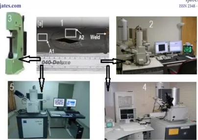
Figure 2.
Setup for methodology (1) collection of tubes, (2) EDS analysis, (3) hardness
measurement, (4) SEM, (5) XRD analysis
3.1 Collection of data and photographic recording
For every kind of failures of high pressure tubes, it is necessary to collect the operational parameters at time
of failures which provides the strong data base for analyzing the failures. Several times, failures also reflect
in terms of operational data, hence, collection of relevant data is essential for analysis of failures.
The inspection at in situ condition of failure of tubes always reveals the useful information about failure.
Several times, it is observed that failure occurs in stages i.e. primary, secondary and tertiary. It means first
failure of tube may become the cause of another tube failure which will be secondary failure and similarly
for tertiary. Hence, photographic recording of in situ tube failures are important for focusing the failure
analysis area to particular failed tube.
3.2 EDS analysis
Energy – dispersive X ray analysis, sometimes called energy dispersive X – ray analysis, is an analytical
technique used for the elemental analysis or chemical characterization of a samples. It relies on an
interaction of some source of X – ray excitation and a sample. Its characterization capabilities are due in
large part to the fundamental principle that each element has a unique atomic structure allowing a unique set
of peaks on its electromagnetic emission spectrum.
To stimulate the emission of characteristic X-rays from a specimen, a high-energy beam of charged particles
such as electrons or protons, or a beam of X-rays, is focused into the sample being studied. At rest, an atom
within the sample contains ground state (or unexcited) electrons in discrete energy levels or electron shells
bound to the nucleus. The incident beam may excite an electron in an inner shell, ejecting it from the shell
while creating an electron hole where the atom was. An electron from an outer, higher-energy shell then fills
released in the form of an X-ray. The number and energy of the X- rays emitted from a specimen can be
measured by an energy-dispersive spectrometer. As the energies of the X-rays are characteristic of the
difference in energy between the two shells and of the atomic structure of the emitting element, EDS allows
the elemental composition of the specimen to be measured.
Four primary components of the EDS setup are:
The excitation source, X-ray detector, Pulse processor, Analyser
3.3 SEM
A SEM (Scanning electron microscope) is a type of electron microscope that produces images of a sample
by scanning the surface with a focused beam of electrons. The electrons interact with atoms in the sample,
producing various signals that contain information about the sample’s surface topography and composition. The electron beam is scanned in a raster scan pattern, and the beam’s position is combined with the detected signal to produce an image. SEM can achieve resolution better than 1 nanometer. Specimen can be observed
in high vacuum in conventional SEM, or in low vacuum or wet conditions in variable pressure or
environmental SEM, and at a wide range of cryogenic or elevated temperatures with specialized instruments.
The most common SEM mode is detection of secondary electrons emitted by atoms excited by the electron
beam. The number of secondary electrons that can be detected depends, other things, on specimen
topography. By scanning the sample and collecting the secondary electrons that are emitted using a special
detector, an image displaying the topography of the surface is created.
3.4 XRD
X-ray diffraction (XRD) is a rapid analytical technique primarily used for phase identification of a
crystalline material and can provide information on unit cell dimensions. The analyzed material is finely
ground, homogenized, and average bulk composition is determined. The periodic lattice found in crystalline
structure may act as diffraction grating for wave particles of electromagnetic radiation with wavelength of a
similar order of magnitude. The atomic plane of a crystal causes an incident beam of X-rays to interfere with
one another as they come out from the crystal. This phenomenon is called X-ray diffraction.
X-ray diffractometers consist of three basic elements:
An X-ray tube, A sample holder, And an X-ray detector.
X-rays are generated in cathode in cathode ray tube by heating a filament to produce electrons, accelerating
the electrons towards a target by applying a voltage, and bombarding the target material with electrons.
When electrons have sufficient energy to dislodge inner shell electrons of the target material, characteristic
X-ray spectra produced. These spectra consists of several components, the most common being Kα and Kβ.
Kα consists, in part, of Kα1 and Kα2. The specific wavelengths are characteristic of the target materials (Cu,
Fe, Mo, Cr). These X-rays collimated and directed onto the sample. As the sample and detector are rotated,
the intensity of the reflected X-rays is recorded.
When the geometry of the incident X-rays impinging the sample satisfies the Bragg Equation, constructive
interference occurs and a peak in intensity occurs.
(1)
A detector records and processes this X-ray signal and converts the signal to a count rate which is then
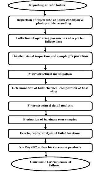
3.5 Systematic Approach
A flow diagram is shown in Figure 3 consisting of all steps for conducting the failure analysis of any tube of
pressure parts.
IV.CONCLUSION
The exact cause of failure of any tube of pressure parts of boiler is very difficult at operating point. All data
from operating norms to microstructure of tube materials change frequently during service condition and any
improper operation or wrong maintenance practice may lead to failure of tubes. The developed generalized
methodology is best suitable to find out the exact cause of failure of tubes. This may be applicable to any
pressure parts i.e. Economizer, Water Wall, Reheater and Superheater tubes.
REFERENCES
[1] Dennies, D.P. How to Organize a Failure Investigation.ASM International, Ohio, 2005.
[2] Duda, P., Felkowski, L., Dobrzański, J., An analysis of an incident during the renovation work of a
power boiler superheater. Engineering Failure Analysis, vol. 57, (2015), p. 248-253,
DOI:10.1016/j.engfailanal.2015.07.011.
[3] Movahedi-Rad, A., Plasseyed, S.S., Attarian, M., Failure analysis of superheater tube. Engineering
Failure Analysis, vol. 48, 2015, p. 94-104, DOI:10.1016/j.engfailanal.2014.11.012.
[4] Nieslony, P., Cichosz, P., Krolczyk, G.M., Legutko, S., Smyczek, D., Kolodziej, M., Experimental
studies of the cutting force and surface morphology of explosively clad Ti–steel plates. Measurement,
vol. 78, 2016, p. 129-137, DOI:10.1016/j.measurement.2015.10.005.
[5] Purbolaksono, J., Ahmad, J., Beng, L. C., Rashid, A.Z., Khinani, A., Ali, A.A., Failure analysis on a
primary superheater tube of a power plant. Engineering Failure Analysis, vol. 17, no. 1, 2010, p.
158-167, DOI:10.1016/j.engfailanal.2009.04.017.
[6] Port, R.D., Herro, H.M., The NALCO Guide to Boiler Failure Analysis. Nalco Chemical Company,
McGraw-Hill, New York,1991.
[7] Ryder, D.A., Davies, T.J., Brough, I., Hutchings, F.R., General practice in failure analysis. Failure
analysis and prevention. Metals handbook, American Society for Metal, Ohio, 1986.
[8] Srikanth, S., Ravikumar, B., Das, S.K., Gopalakrishna, K., Nandakumar, K., Vijayan, P., Analysis of
failures in boiler tubes due to fireside corrosion in a waste heat recovery boiler. Engineering Failure
Analysis, vol. 10, no. 1, 2003, p. 59-66,DOI:10.1016/S1350-6307(02)00030-4.
[9] Vander Voort, G.F., Conducting the Failure Examination Practice. ASM Handbook, ASM
International, Ohio, 2002.
[10] Xu, L., Khan, J. A., Chen, Z., Thermal load deviation model for superheater and reheater of a utility
boiler. Applied Thermal Engineering, vol. 20, no. 6, 2000, p. 545-558, DOI:10.1016/
S1359-4311(99)00049-6.
[11] Ranjbar, K., Failure analysis of boiler cold and hot reheater tubes. Engineering Failure Analysis, vol.
14, no. 4, 2007, p. 620-625, DOI:10.1016/j.engfailanal.2006.03.007.
[12] Ahmad, J., Rahman, M., Zuhairi, M.H.A., Ramesh, S., Hassan, M.A., Purbolaksono, J., High
operating steam pressure and localized overheating of a primary super heater tube. Engineering
[13] Ananda Rao, M., Sankara Narayanan, T.S.N., Failure investigation of a boiler bank tube from a 77 ×
2 MW coal based thermal power plant in the northwest region of India. Engineering Failure Analysis,
vol. 26, 2012, p. 325-331, DOI:10.1016/j.engfailanal.2012.04.013.
[14] Hanke, N., Evaluation of a failed water wall boiler tube. Journal of Failure Analysis and Prevention,
vol. 12, no. 1, 2012, p. 11-15, DOI:10.1007/s11668-011-9522-4.
[15] Jones, D.R.H., Creep failures of overheated boiler, superheater and reformer tubes. Engineering
Failure Analysis, vol. 11, no. 6, 2004, p. 873-893, DOI:10.1016/j.engfailanal.2004.03.001.
[16] Shokouhmand, H., Ghadimi,B., Espanani, R., Failure analysis and retrofitting of superheater tubes in
utility boiler. Engineering Failure Analysis, vol. 50, 2015, p. 20-28, DOI:10.1016/j.
engfailanal.2015.01.003.
[17] Saha, A., Shukla, A.K., Failure of a secondary superheater tube in a 140-MW thermal power plant.
Journal of Failure Analysis and Prevention, vol. 14, no. 1, 2014, p. 10-12,
DOI:10.1007/s11668-013-9773-3.
[18] Movahedi-Rad, A., Plasseyed, S.S., Attarian, M., Failure analysis of superheater tube. Engineering
Failure Analysis, vol. 48, 2015, p. 94-104, DOI:10.1016/j.engfailanal.2014.11.012.
[19] Hu, Z.F., He, D.H., Wu, X.M., Failure analysis of T12 boiler re-heater tubes during short-term
service. Journal of Failure Analysis and Prevention, vol. 14, no.5, 2014, p.637-644,
DOI:10.1007/s11668-014-9859-6.
[20] Javidi, M., Nematollahi, M. R., Lalehparvar, M.M., Ghassemi, A., Failure analysis of AISI 321
austenitic stainless steel water piping in a power plant. Journal of Failure Analysis and Prevention,