© 2018 IJSRST | Volume 4 | Issue 2 | Print ISSN: 2395-6011 | Online ISSN: 2395-602X Themed Section: Science and Technology
Design Calculations for Agriwaste Briquette Making Machine
Arpita A. Gulhane1, Dr. C. C. Handa21Research Scholar, Department of Mech. Engg. KDKCE, Nagpur, Maharashtra, India 2Professor & Head, Department of Mech. Engg. KDKCE, Nagpur, Maharashtra, India
ABSTRACT
This paper presents the design calculation of Agriwaste Briquette making machine. Assumptions and references are taken for designing the Agriwaste Briquette making machine. The design calculation of Agriwaste Briquette making machine is done. For developingAgriwaste Briquette making machine, various componentdesign of chain drive, design of connecting rod, design of ratchet and pawl,design of rack and pinion, pedal mechanism.
Keywords : Were Designed And Fabricatedchain Drive, Connecting Rod, Ratchet And Pawl, Rack And Pinion, Pedal Mechanism.
I.
INTRODUCTION
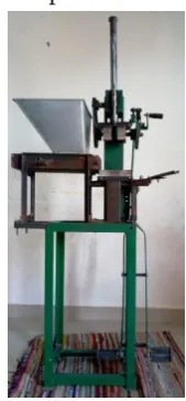
TheAgriwaste Briquette making machine shown in the figure no.1 other than the frame consist of chain drive, sprocket, gear, rack and pinion, ratchet and pawl, rack shaft, press pedal etc.
Figure 1. Agriwaste Briquette Making Machine
II.
DESIGN CALCULATIONS FOR AGRIWASTE
BRIQUETTE MAKING MACHINE
The aim of this is to give the complete design information about the Agriwaste Briquette making machine. In this, the explanations and some other parameters related to the project are included. With
references from various sources as journal, thesis, design data book, literature review has been carried out to collect information related to this project.
A. Design consideration
-Capacity of Agriwaste Briquette Making Machine = 3 Kg
-Force Applied on Pedal = 7350.75 N
-Average Height of Machine According to Human Ergonomics = 165 cm
Design calculations
Determination of agriwaste briquette making machine force experimentally.
1.Design Calculations Of Chain Drive
Figure 3. Actual diagram of Chain Drive
Velocity Ratio, i = 2
Minimum teeth on driver sprocket, Z1 = 16
Standard minimum pitch, p = 12.7mm
C. C. distance between two shafts, a = 152mm
Calculations Velocity Ratio, i =
.∙.Teeth on Driven Sprocket, = 32 Pitch Diameter, D =
.∙.Pitch Diameter of driver sprocket, D1
D1=P/Sin(180/Z1)=65mm
.∙.Pitch Diameter of driven sprocket, D2
D2=P/Sin(180/Z2)=129.5mm
Number of links in the chain, Ln
Ln=2( )+( )+
×( )
Ln=48.4788 i.e.
Ln=49 Numbers of links.
Length of chain,L L=Ln x p
L=622.3mm
Now, From Table No.14.1
Selecting chain, ISO chain number 08B Pitch, p=12.7mm
Roller diameter, d1(max)=8.51mm
Width, b1(min)=7.75mm
Transverse pitch, pt=13.92mm
Breaking load (minimum)=17800N
Power rating of chain = Where,
KS=Service Factor
K1=Multiple Strand Factor
K2=Tooth Correction Factor
From Table No.14.2
Taking pinion speed 50RPM, & for the ISO chain number 08B
Power rating of chain=0.34KW
From Table No.14.3
For heavy shock & electric drive Service factor KS=1.4
From Table No.14.4 For single strand,
Multiple strand factor K1=1.0
From Table No.14.5 For 16 teeth,
Tooth correction factor, K2=0.92
Power rating of chain = Power to be transmitted = 0.2234 K
Top diameter (Addendum Diameter)-Da
From Table No.14.6 Da (max)=D2+1.25p – d1
Da (max)=136.865 mm
Da (min)= D1 + p x(1- ) - d1
Da (min) = 67.92mm
Top diameter of driven sprocket, Da2=136.865mm
Top diameter of driver sprocket,Da1=67.92mm
Root diameter (Dedendumdia), DF
DF= D – 2ri
Roller seating radius, ri
(ri) max = 0.505d1+0.069 x √
(ri) max = 4.438 mm
(ri) min = 0.505d1
(ri) min = 4.297 mm
DF(min) = D1 – 2 rimin
DF (min) = 56.406 mm
DF (max) = D2 – 2rimax
DF (max) = 120.624 mm
(re) Driven = 0.008 d1( +180)
(re) Driven =81.968 mm
(re) Driver = 0.12d1(Z1 + 2)
(re) Driver = 18.38 mm
Roller Seating Angle, α For, Driven Sprocket,αDriven
αDriven=(120 – )
α Driven =117.2o
For, Driver Sprocket, α Driver
αDriver= (140- )
α Driver= 134.4o
Tooth height above the pitch polygon, ha
For Driven Sprocket, (ha)Driven
(ha) Driven = 0.625p – 0.5d1 +
(ha) Driven = 4 mm
For Driver Sprocket, (ha) Driver
(ha) Driver = 0.5(p – d1)
(ha) Driven = 2 mm
Tooth side radius, rx
rx (min) = p = 12.7mm
Tooth width, bf1
bf1 = 0.93 b1 if p ≤ 12.7 mm
bf1 = 0.95 b1 if p > 12.7 mm
bf1 = 0.93 b1
bf1 = 7.2 mm
Tooth side relief, ba
ba= 0.1p to 0.15p
Taking ba= 0.15p
.∙.ba= 1.9 mm
Power transmitted by chain drive
Power transmitted by chain drive = Force caused by driver shaft rotation x average (minimum) velocity of chain drive
.∙.Force caused by driver shaft rotation = 50 x 9.81 = 490.5 N
223.4 = 490.5 x minimum velocity of chains drive, V .∙.V = 0.455 m/sec.
2.Design Calculations Of Rack And Pinion Selecting profile type of tooth is 20o full depth
Assuming preferred no. of teeth on pinion, TP = 7
A) Pinion
Pitch diameter of Pinion, DP = TP x m mm.
Since, NP = 2880 rpm.
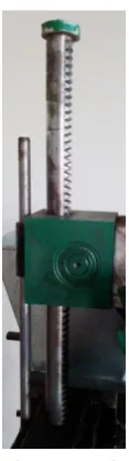
Figure 4. Proposed Rack and Pinion
Figure 5. Actual diagram of Rack and Pinion VP = π× TP×
×NP8 VP = π× TP×
×NP8 VP= 1.055m m/sec
Design Power, PD
From Table XVI – 1 PD = PR x K1
PR= 1 HP = 746 Watt
From table XVI – 2 K1 = 1.80
PD = 746 x 1.80 = 1342.8 Watt
FT =
FT = 1272.19/ m N
From Table XVI – 10
Selecting material is Cast Steel 0.20% Carbon Heat Treated Basic Stress of Pinion, So = Syt = 196 N/mm2
From Table XVI – 1
Bending Stress by Lewis Equation,FB
FB = SO x CV x b x y x m
From table XVI – 5
For Involute Gear, 20˚ full depth
Modified Lewis from factor, Y = 0.485 – Y = 0.075
From table XVI – 7
Face width, b = 10m mm or b = DPmm
Assuming the Velocity Factor,CV = 0.25
Bending Strength, FB = SO × CV× b × Y × m
FB = 36.75m2 (2)
Equation (1) and (2) i.e. FT = FB
m3 = 34.6175
Module m = 3.259 mm m3 =
FT = 254.438N
From Table XVI – 7
Selecting Standard Module, m = 5 mm Pitch Diameter, DP = TP x m
DP = 7 x 5 = 35mm
Face Width, b = DP = 35mm.
Tangential tooth load, FT
FT =
FT = 254.438N
Bending Strength, FB
FB = 36.75m2 = 36.75x 52
FB = 918.75 N
Pitch line velocity, VP
VP = 1.0555m = (1.0555x 5)/1000
VP = 0.005277 m/sec
Pitch Peripheral Length= π × DP
= 109.955 ≈ 110 mm
B) RACK SHAFT
Total length of the rack shaft, LT
LT = 975 mm
Load applied on the rack shaft 75KgF
Applied load = 75 x 9.81 = 735.75 N From table II – 7
Selecting material of rack is carbon steel, SAE1030 Sut = 527 MPa; Syt = Syc = 296 MPa
E = 204 MPa
Effective length, LE = 270mm
Total load,W= 735.75 N
Factor of safety, FOS = 2 (Assumed) Area moment of Inertia, I
I =
Crippling load,
WCr = FOS x W = 2 x 735.75
WCr = 1471.5N
According to Euler formula WCr =
(n=2 –taking one end fixed and other hinged) I = 26639.61 mm4
D = 27.14 mm From table XI – 4
Selecting available size, D = 28 mm
3. Design Calculations Of Shafts
A) SHAFT 1 (ratchet and larger sprocket) Total Length = 225 mm
Power rated = 1 HP = 746Watt Rotation = 1440rpm
Design power , PD = 1342.8 Watt
Considering shaft subjected to twisting moment only. So, neglecting the bending moment on the shaft. From Table II – 7,
Selecting Carbon Steel, SAE 1030 Sut = 527MPa; Syt = 296MPa
Sys = 183 MPa; E = 204MPa
Torque transmitted by shaft, T T =
T = 8.9047 Nm
Torque transmitted by shaft, T T = x Ʈ x d3
d = 7.91 mm From Table XI – 7,
Selecting Dia. of Shaft, d = 10mm
B) SHAFT- 2 (small sprocket to pinion) Total Length = 140 mm
Design power , PD = 1342.8 Watt
Rotation = 2880rpm From Table II – 7,
Selecting Carbon Steel, SAE 1030 Sut = 527MPa; Syt = 296MPa
Sys = 183 MPa; E = 204MPa
Working Shear Stress, Ʈ = Taking FOS = 2 Ʈ = 91.5 MPa
Torque Transmitted by Shaft, T T =
T = 4.45 Nm
Torque transmitted by shaft, T T = x Ʈ x d3
d = 6.28 mm From Table XI – 7,
Selecting Dia. of Shaft, d = 10mm
4.Designcal. Of Pedal Mechanism
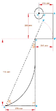
Applying Budhayan–Pythagoras Theorem AC2 = AB2 + BC
AC = 854.28 mm .cos θ = AB/AC .∙.θ = 25.63o
180 = α + θ+ 90 .∙.α = 64.37o
W = 7350.75 N WT = Tangential Load
WP= ParallelLoad
WTA = W sin θ
WTA = 318.25 N
Figure 6. Line Diagram of Pedal Mechanism
Figure 7. Forces on Pedal Link
Using Equilibrium Condition of Couple WTA x 854.28 = WTB’ x 245
WTB’ =1109.7N
VerticleForce Acting on Point B FTV = WTB’cos α
FTV = 479.71 N= WVB”
Figure 8. Torque Diagram
WVB” = WVD = 479.71N
TVD = WVD x OD
TVD = 103136.9 Nmm
Torque Developed at the Periphery of Ratchet TRATCHET= TVD = X = 33579.48 Nmm
5.Ratchet And Pawl Mechanism
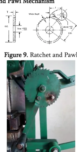
Figure 9. Ratchet and Pawl
Figure 10. Actual Diagram of Ratchet and Pawl
A) Ratchet
Force Applied on Ratchet Teeth, F = 479.71 N Material Selected; Carbon Steel; SAE 1030 Sys = 183 MPa Taking FOS =6
Working Shear Stress, Ʈ = = 30.5 MPa
Figure 11. Force on Ratchet Tooth
Required Area of Base of Ratchet Tooth AR =
AR = 15.73 mm2
t = b = 4mm
Available Thickness, t = 10mm Available Width, b = 12m .∙.Available Area, AA = 120 mm2
So, Ratchet Design is Safe.
B) PAWL
Force Applied on Ratchet Teeth, F = 479.71 N
Material Selected; Carbon Steel; SAE 1030 Syc = 296 MPa Taking FOS = 6
σc =
.∙.σc = 49.33 MPa
Figure – Force on Pawl Required Cross Section Area,
AR = F/σc
.∙.AR = 9.72 mm2
t = b = 3.11 ≈ 4 mm2
Available Thickness, t = 7 m Available Width, b = 12 mm .∙.Available Area, AA = 84 mm2
So, Ratchet Design is Safe.
III. CONCLUSION
The designs of various parts and parameters are taken into consideration and above values obtained successfully. These values are implemented of fabrication of same machine which is working successfully.
IV. REFERENCES
[1]. Arpita A. Gulhane,kdk college of Engg.,Dr.C. C. Handa,HOD,kdkce,"A review on Briquetting Machine for Agriwaste","International Journal
for Scientific Research and
Development",1/8/2017 Vol:5,Issue:5 pages:664-667.
[2]. Design Data Book, Prof. B. D. Shiwalkar, Denett Publication, 2015 Edition.
[4]. ATextBook of Mech System Design, FarazdakHaideri, Third Edition, Ch 2, Page No. 149-241.
[5]. Mechanics of Materials I,Third Edition, E. J. Hearn,University of Warwick,United Kingdom, Chapter 1, Page No. 1-8.
[6]. Mechanical Vibrations, ThammaiahGowda, Jagadeesha T, D. V. Girish, Tata Mcgraw Hill Education Private Limited,Page No. 44, Topic-Spring Element.
[7]. Design of Machine Element, V. B. Bhandari, McGraw Hill Education Private Limited, Third Edition, 11th reprint, 2013.
[8]. Arpita A. Gulhane, kdk college of Engg.,Dr.C. C. Handa,HOD,kdkce, "Mechanisms used in Agriwaste Briquette Making Machine".