Vol. 06, Issue 01 (January. 2016), ||V4|| PP 26-30
Quad-Channel Seamless Handover Scheme for Vehicular
Networks
Ronny Yongho Kim
Korea National University of Transportation, Department of Railroad Electrical and Electronics Engineering Gyeonggi, Uiwang, Korea,
Abstract: - In this paper, a seamless handover scheme using 4 channels for vehicular networks is proposed. IEEE 802.11p defines multi-channel operation in order to provide multi-channel service to single physical module devices. In order to provide reliability, multiple physical module devices can use multiple channels simultaneously. Reliable communication using multiple physical modules is possible not only during normal communication but also during handover. In this paper, an efficient seamless handover scheme using 4 wireless channels is proposed. With the proposed scheme, zero handover interruption time can be achieved. Seamless handover can be achieved with two wireless channels and further reliability can be achieved with additional two wireless channels.
Keywords: - IEEE 802.11p, ITS, Multi-channel, Quad-channel, WAVE
I.
INTRODUCTION
As the more devices are connected to the network, the broader wireless access services need to be provided. Various wireless access technologies are being used such as 3GPP Long Term Evolution (LTE) [1], IEEE 802.16m based WiMAX [2], and IEEE 802.11 based Wireless Local Area Network (WLAN) [3] to provide broadband wireless services. For various applications, WLAN has been used due to its easy deployment and excellent data communication capability [4], [5]. WLAN is able to provide broadband services thanks to its plenty of license exempt wireless bands. WLAN can be deployed without regulations. As mobility support is norm for wireless services, WLAN is also used for vehicular services including Intelligent Transportation Services (ITS). For such reason, new IEEE 1609 series standards, Wireless Access in Vehicular Environments (WAVE) [6], [7], [8], [9] can be used to support vehicular communication with WLAN. WAVE is used for various vehicular services such as automatic tolling system, and so on, [11], [12], [13].
Unlike to other cellular systems, current IEEE 802.11 based WAVE system does not support mobility. Because of the distributed network configuration of WLAN, mobility support is very difficult. However, because WAVE system is allowed to access the network simply by using IEEE 802.11p air interface. In some vehicular systems like railroad systems require high reliability. In order to provide high reliability, redundancy configuration needs to be supported. In WAVE systems, multiple wireless channels can be utilized to provide various services. There are two kinds of WAVE multiple channels: Service Channel (SCH) and Control Channel (CCH).
II.
ITS
SYSTEM
CONFIGURATION
Fig. 1 shows the proposed ITS system architecture considering all possible components such as pedestrian, car (road system), and train (railroad system). There may or may not exist control center for smart ITS services but in the system architecture shown in Fig. 1, control center is configured for centralized control. Different types of ITS users such as person, car, and train are connected to the ITS system through Road Side Units (RSUs). Interface between ITS users and RSU is called Vehicle to Infrastructure (V2I) interface. ITS users need to communicate each other using the air interface called Vehicle to Vehicle (V2V) interface. In some cases, RSUs need to communicate each other using the interface called Infrastructure to Infrastructure interface (I2I), which is not defined in the standards. Since communication distance between trains, railroad system may not provide V2V communication. For such case, new communication type, V2V with I2I needs to be newly defined. V2V with I2I is communication a inter vehicle communication when direct communication is not possible due to its long communication distance. In this case, RSUs relay one vehicle’s packets to the destination vehicles. From the vehicles’ perspective, RSUs’ relay should be seen transparently. By utilizing the proposed ITS system architecture, total ITS services can be provided and the proposed handover scheme can be performed with maximum efficiency.
In order to provide reliable communication, redundancy architecture should be considered. In some applications like railroad, one of very critical requirements is reliability. In order to provide reliability, multiple channel allocation can be considered. We can provide reliability using two WAVE channels. However, in case of using two WAVE channels, redundancy cannot be guaranteed because one channel is used for communication with the serving RSU and the other channel is used for performing control signaling with the target RSU during handover. Therefore, we propose to use quad channels, i.e., 4 channels to reliability to ITS system. Quad channel allocation is shown in Fig. 2. As we can see from the figure, when WAVE user, On Board Unit (OBU) communicates with the serving RSU, it uses Ch. #1 and Ch. #2 which provide a redundancy structure. During handover, currently used Ch. #1 and Ch. #2 is remained and new two channels, Ch. #3 and Ch.
#4 are used to perform handover. After handover, Ch. #1 and Ch. #2 are released and Ch. #3 and Ch. #4 are used for communication with the RSU. By using quad channels, redundancy structure can be ensured all the time.
Fig. 3 shows the OBU protocol architecture for quad channel operation. Since, at maximum, the OBU has to use 4 WAVE channels, there are 4 physical modules. Logically, two modules are assigned as primary and the other two modules are assigned as secondary. Primary two physical modules become secondary after handover which will be explained in detail later. In order to perform the WAVE convergence functions such as packet combining, error correction using quad channels, and redundant packet elimination, WAVE entity, which is logical entity, resides on top of four WAVE modules. Since WAVE entity is able to manage 4 WAVE modules, it also provides handover related functions.
III.
PROPOSED
QUAD
CHANNEL
Fig. 4 shows how quad channels are used for normal communication and handover. RSUs can be well planned because they are normally deployed along roads. Two RSUs or one RSU with two channels can be in charge of one serving area, a cell. Cells are located to have overlapping area for seamless handover operation. As we can see from Fig. 4, the car in the middle is the location where it can receive all signals from RSU#1,
Ch #2 Ch #1
RSU#1 RSU#2
W1 W2 W3 W4 RSU#4
W1 W2 W3 W4 W1 W2 W3 W4
Ch #4 Ch #3
RSU#3
Communication during Handover
Fig. 4. Quad Channel Handover PHY2
MAC2 LLC2
WAVE Entity (Convergence Manager, Handover Manager, etc)
PHY1 MAC1 LLC 1
PHY4 MAC4 LLC4
PHY3 MAC3 LLC 3
Primary Secondary
(Handover)
RSU#2, RSU#3, and RSU#4. Two cells adjacent each other should use different channel sets. For example, as in the Fig. 4, one cell uses Ch.#1 and Ch.#2 and the other cell uses Ch.#3 and Ch.#4. Since typically linear topology is used for ITS, compare to normal cellular systems ITS cells using different channels are easy to configure and also OBUs are easy to predict the channels of the adjacent cells. When signal quality of the serving RSU goes below the handover threshold, OBU starts scanning to find target RSUs using the other two modules. When the new target RSUs are found, OBU performs handover procedure using the two modules while the other two modules keep communicating with the serving RSU. Therefore, two channels are used for handover signaling and two channels are used for communication with the serving RSU which provide the perfect redundancy configuration. After successful handover, the two modules used for handover signaling are used for communication with the new RSU and the connections of the other two modules used for communication with the previous RSU are released.
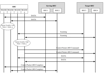
The proposed quad-channel handover protocol is shown in Fig. 5. OBU has 4 modules, WAVE 1 through 4, to access 4 WAVE channels. By using WAVE 1 and WAVE 2 modules, the OBU communicates with the serving RSU which is a serving cell and consists of RSU1 and RSU2. The OBU keeps monitoring the signal quality of the current connection. When the signal quality, Received Signal Strength Indicator (RSSI) of the current connection goes below the predefined threshold, RSSI_s, the OBU initiates handover procedure by performing scanning. As a result of scanning, new target RSU with strong enough signal quality of RSSU_t can be found. When new target RSU with good RSSI is determined, the OBU transmits a Handover Command control packet using WAVE 3 and WAVE 4 to the new RSU, RSU 3 and RSU 4. Transmitting a control packet is to register the OBU to RSUs’ Address Resolution Protocol (ARP) table. Once ARP table is updated, packets to the OBU will be delivered to the new RSUs. Therefore, the OBU is able to receive data from the new RSU. After successful data reception from the new RSU, the OBU transmits a Handover Complete control packet using WAVE 1 and WAVE 2 to the serving RSU. The main objective of the transmission of a Handover Complete control packet is to update the old RSU’s ARP table to delete the OBU’s entry.
IV.
CONCLUSION
In this paper, a seamless handover scheme using Quad channels (4 channels) for vehicular networks is proposed. Also redundancy structure using multiple channels with focus on seamless handover is proposed. In
OBU
RSU1
DATA
RSU2 WAVE
1
WAVE 2
WAVE 3
WAVE 4
Serving RSU
RSU3 RSU4
Target RSU
DATA
Signal Quality Low RSSI < RSSI_s
Scanning Scanning
Signal Quality High RSSI > RSSI_t
Control Packet (HO Command)
Control Packet (HO Command)
DATA DATA
Control Packet (HO Complete)
Control Packet (HO Complete)
passenger safety is highly dependent on the system. By using the proposed scheme, very reliable redundant configuration is possible even during handover. With the proposed architecture and scheme, future ITS systems like connected smart car system will be able to provide safe and seamless services.
V.
ACKNOWLEDGEMENTS
This research was supported through the Institute for Information & Communication Technology Promotion (IITP) funded by the Ministry of Science, ICT & Future Planning (R0166-15-1030).
REFERENCES
[1] 3GPP Technical Specification 36.300, "E-UTRA and E-UTRAN Overall Description Stage 2 (Release 10 )", www.3gpp.org
[2] “IEEE Standard for Local and metropolitan area networks Part 16: Air Interface for Broadband Wireless Access Systems Amendment 3: Advanced Air Interface,” IEEE Std 802.16m-2011, May 12 2011. [3] “IEEE Standard for Information Technology-Telecommunications and information exchange between
systems Local and metropolitan area networks--Specific requirements Part 11: Wireless LAN Medium Access Control (MAC) and Physical Layer (PHY) Specifications,” IEEE Std 802.11-2012, 2012
[4] Mohamed M. Abo Ghazala, Mohamed F. Zaghloul, and Mohammed Zahra, “Performance Evaluation of Multimedia Streams Over Wireless Computer Networks (WLANs),” International Journal of Advanced Science and Technology, Vol. 13, pp 63-76, December 2009
[5] Raja Hasyifah Raja Bongsu, Nazirah Abd. Hamid, Ahmad Nazari Mohd. Rose and Shamala Subramaniam, “Enhanced Packet Scheduling Algorithm for Multihop Wireless LANs,” International Journal of Advanced Science and Technology, Vol. 49, pp 63-72, December 2012
[6] IEEE Std 1609.1-2006 - IEEE Trial-Use Standard for Wireless Access in Vehicular Environments (WAVE) - Resource Manager, 13 Oct 2006.
[7] IEEE Std 1609.2-2013 - IEEE Standard for Wireless Access in Vehicular Environments—Security Services for Applications and Management Messages, 26 Apr 2013.
[8] IEEE Std 1609.3-2010 - IEEE Standard for Wireless Access in Vehicular Environments (WAVE) - Networking Services, 30 Dec 2010
[9] IEEE Std 1609.4-2010 - IEEE Standard for Wireless Access in Vehicular Environments (WAVE) - Multi-channel Operation, 7 Feb 2011.
[10] IEEE 802.11p-2010 - Wireless LAN Medium Access Control(MAC) and Physical Layer (PHY) Specifications Amendment 6: Wireless Access in Vehicular Environments, IEEE Standards Association, 2010.
[11] http://standards.ieee.org/develop/wg/1609_WG.htm
[12] DSRC Implementation Guide - A guide to users of SAE J2735 message sets over DSRC. SAE International, 2010