52 |
P a g e
A SURVEY OF TECHNIQUES AND DESIGN FOR MICROSTRIP PATCH
ANTENNA
Mrs. Kamini U. Gaikawad
Asst Prof, E& TC Dept., MMCOE, Karvenagar, Pune
Mrs. Rashmi P. Belokar
Asst Prof, E& TC Dept., MMCOE, Karvenagar, Pune
ABSTRACT:
In today’s growing world, Microstrip also known as patch antennas are becoming more useful as they can be printed openly onto a circuit board. The Microstrip antennas are also very useful within the mobile phone market. Patch antennas are low profile, low cost and are easily fabricated. In telecommunication, there are several types of microstrip antennas and the frequently used is the patch antenna or microstrip patch antenna. Microstrip antennas are relatively economical to design and assemble because of feature like simple 2-dimensional physical geometry. They are usually employed at UHF and higher frequencies because the size of the antenna is directly tied to the wavelength at the resonant frequency. A single patch antenna has ability to provide maximum directive gain of around 6-9dBi. It is relatively easy to print an array of patches. Patch arrays can gives greater gains at little additional cost; matching and phase adjustment is possible to perform with printed microstrip feed structures, again in the same operations that form the radiating patches. The patch antenna has is able to create high gain arrays in a low-profile which make it applicable on airplanes as well as in other military applications. KEYWORDS: Microstrip antenna, Dielectric, Patch Length, feed techniques, Patch width, etc.
INTRODUCTION:
The parameters of antenna get affected because of dielectric loading of a microstrip antenna. The reduction in antenna bandwidth is done with increase in dielectric constant of the substrate which is in turn helps to increases the Q factor of the antenna which is in turn
reduces the impedance bandwidth. This relationship did not immediately follow in cases like transmission line model of the antenna, but is visible when using the cavity model which was introduced in the late 1970s by Lo et al. The radiation from a rectangular microstrip antenna
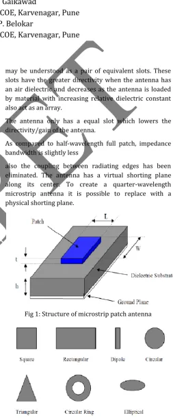
may be understood as a pair of equivalent slots. These slots have the greater directivity when the antenna has an air dielectric and decreases as the antenna is loaded by material with increasing relative dielectric constant also act as an array.
The antenna only has a equal slot which lowers the directivity/gain of the antenna.
As compared to half-wavelength full patch, impedance bandwidth is slightly less
also the coupling between radiating edges has been eliminated. The antenna has a virtual shorting plane along its center. To create a quarter-wavelength microstrip antenna it is possible to replace with a physical shorting plane.
Fig 1: Structure of microstrip patch antenna
53 |
P a g e
LITERATURE SURVEY:
Mithila R. Ghuge et. al. (2014) In the recent era of wireless communication, Microstrip antenna (MSA) is hot research topic attracting attentions of many researchers .MSA are low profile, lightweight and have a compatibility with integrated circuit technology. There are several drawbacks of MSAs likes their narrow impedance, bandwidth, axial ratio, lower power handling capacity small gain etc. Here the overview of air fed high gain patch antenna is presented. Various gain enhancement methods like micro strip antenna array, super strate structure, change in dielectric material and partial removal of substrate will be studied also the presentation of review. Air is used as dielectric medium between feed patch and ground plane.
Vikas et. al. (2014) In this paper an Ultra Wideband (UWB) micro strip antenna consisting of a circular monopole patch along with stepped feed line, a 10 dB return loss bandwidth from 3.1 to 10 GHz is proposed. This antenna was designed on FR4 substrate with overall size of 40 x 31.17 x 0.787 mm3 and dielectric substrate with 𝜀𝑟 = 2.2 This antenna designed by using CST Software based on the characteristic impedance for the transmission line model and operated at UWB frequency . The parameters like feed size, ground plane and substrate dimension which affect the performance of the antenna in terms of its time domain and frequency domain characteristics are investigated.
W. Mazhar et.al. (2013) A novel design of compact micro strip UWB antenna with step impedance micro strip line is proposed. The proposed antenna is analyzed in both frequency and time domain to check its appropriateness for UWB applications. For feeding used connector is SMA female. Antenna features like as return loss and radiation pattern show reasonable agreement with the simulated results. The omni-directional radiation pattern on most of the operating band. Radiation pattern is measured in antenna anechoic chamber. Feed line used has characteristic impedance of 50 -. The antenna consists of a partial ground with slots at the rear end and a rectangular patch with slits on the top face. The antenna with dimension of L=34mm £ W=36mm is fabricated on FR-4 epoxy dielectric with relative permittivity of 4.4. The designed antenna has the capability of operating between 3 GHz to 10.26 GHz with a 7.26 GHz bandwidth (fh-fl).
Mustafa Abu Nasr et.al. (2013) The design and analysis of a new ultra wideband micro strip antenna for optimum performance which fulfilled a greatest bandwidth starting from 3.9GHz to 22.5GHz is
introduced . The techniques of enhancing the bandwidth of microstrip UWB antenna is useful to increase the performance of the designed antenna. The UWB antenna is able of perform over an UWB as allocated by the Federal Communications Commission (FCC) with good properties like radiation in excess of the entire frequency range. The antenna was designed and simulated using High Frequency Structure Simulator HFSS software packages. The effect of shifting feed line from the center of patch to the edges was also considered in count to the effect of changing the length of the ground plane.
M. H. Diallo Yaccoub et. al.(2013) In this paper, we present a new approach to improve the radiation effectiveness and the performance of antennas by miniaturization of the size. The printed antenna is one of the best antenna structures, due to its low cost and compact design. Indeed, we have studied the performance of ultra wideband antenna which consists of a ring-shaped patch. The complete frequency band of UWB which is ranging from 2.5GHz to 9.4GHz and the geometry of the antenna and to obtained results the simulation software CST Studio microwaves is used.
54 |
P a g e
DIFFERENT TECHNIQUES:
Sr. No
Title Technique Input parameter Output parameter
1 Novel Modified UWB Planar Monopole Antenna With Variable Frequency Band-Notch Function [3]
In this paper H- shape was designed on patch antenna and also two square slots are inserted on ground plane. This DGS provide an additional current path.
Ground-22×22mm2 Patch length-13.5mm Patch width -10mm feed line length-8mm Feed line width-1.86mm
(VSWR<2) for frequency band of 3.1 to over 13.9 GHz with rejection band around 5.1 to 6 GHz.
2 Single Layer Dual band G-shaped patch antenna[2]
A G- shape slot was cut on the patch for bandwidth magnification.
Dielectric constant =2.2
Substrate thickness=4mm
Patch length (L) =30mm
Patch width(W) =40mm
At frequency 3 GHz
BW= 500 MHz Gain = 7.5 dBi Return loss= -17 dBi
At frequency 3.8 GHz
BW= 400 MHz Gain= 2.4 dBi Return loss= -15dBi 3 An Edge Tapered
Rectangular Patch Antenna with Parasitic Stubs and Slot for Wideband Applications [1]
A rectangular patch antenna with tapered edge was designed. The slot and parasitic stubs were also used for this design.
FR4 Epoxy Glass was used as substrate with thickness of 1.6 mmDielectric constant of substrate= 4.4Antenna size=35 ×35 ×1.6 mm3.
Percentage Bandwidth = 112% (centered at 6.01
GHz)
Average radiation efficiency= 83.9%
4 Micro strip Symmetrical
E-Shape Patch Antenna for the Wireless
Communication Systems [7]
E shape antenna was
designed by cutting two slots from rectangular patch.
Resonant frequency
fr 3.1GHz co-axial feed line was used. Ground plane-41×31 mm2
Patch-31×21 mm2
Gain = 4.7 dB
Return loss = -28 dB
5 Multi-Port Network Approach for the Analysis of Dual Band Fractal Micro strip Antennas [4]
Fractal Minkowski geometry was used. In Minkowski initiator is divided into three equal parts of length and by two horizontal and a vertical segment of equal length middle segment was replaced.
Ground plane of aluminum of dimensions 2 0 cm× 20 cm was used.
At first iteration
Fr1= 2.95 GHz
BW= 38 MHz Gain = 5.98 dBi At 2nd iteration Fr2= 4.725 GHz BW= 59.8 MHz Gain= 5.3 dBi
6 Wideband fractal shaped slot antenna for X-band application [5]
Fractal geometry was used. A second iteration fractal shaped cross slot is fabricated along the centre of the broadwall of a rectangular waveguide.
At 1st iteration length
and width of + sign was 15mm and 2mm. At 2nd iteration length and width of + sign was 5.4mm and
72mm.
Bandwidth
magnification better than 2 GHz and 2 GHz 3 dB pattern
bandwidth was obtained.
55 |
P a g e
PARAMETERS OF MICROSTRIP PATCH ANTENNA:
The Figure 3 shows frequency of operation of the patch antenna determination by the length L.
Fig 3: Side View of Microstrip Antenna
The center frequency will be :
The above equation states that the microstrip antenna should have a length equal to one half of a wavelength within the substrate medium. The input impedance of the microstrip antenna gets control with the help of width of antenna. Increase in widths results more bandwidth & reduction in impedance. For a square patch antenna fed in the manner above, the input impedance will be on the order of 300 Ohms. However, to decrease the input impedance upto 50 Ohms is the requirement of very wide patch antenna, which takes up a lot of valuable space. The width also helps to controls the radiation pattern. The following equations gives normalized radiation pattern:
In the above, k is the free-space wave number, given
by . The magnitude of the fields, given by:
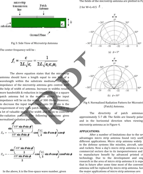
The fields of the microstrip antenna are plotted in Figure 2 for W=L=0.5 .
Fig 4. Normalized Radiation Pattern for Microstrip (Patch) Antenna.
The directivity of patch antennas is approximately 5-7 dB. The fields are linearly polarized, and in the horizontal direction when viewing the microstrip antenna as in Figure 4.
APPLICATIONS:
56 |
P a g e
pocket size equipment, cellular phones, UHF pagers and the radar applications in vehicles like car, planes, and ships. Various types of designs are made and used for radar applications like marine radar, radar for surveillance and for remote sensing.
Satellite Communication: - In satellite communication antenna should have the circular polarization. One of the major benefit of micro strip antenna is that one can easily design an antenna with require polarization by using dual feed networks and different techniques. Parabolic antennas are used in satellite communication to broadcasting from satellite. A flat micro strip antenna array can be used in the place of parabolic reflector. Global Positioning System :- Initially the satellite based GPS system are used for only in military purposes but now a day’s GPS found a large application in everyone’s life and now used commercially. GPS found an essential requirement in vehicles, ships and planes to track the exact location and position. 24 satellites are working in GPS encircling the earth in every 12 hours at altitude 20,200 km. GPS satellite using two frequencies in L-band to transmit the signal which is received by thousands of receivers on earth. The receiver antenna should be circularly polarized. An Omni-directional micro strip antenna has wide beam and low gain can be easily design with dual frequency operation in L-band.
Direct Broadcast Satellite System:- In many countries direct broadcasting system is used to provide the television services. A high gain (~33db) antenna should be used at the ground by the user side. A parabolic reflector antennas are generally used are bulky requires space and affected by snow and rain. An array of circularly polarized micro strip antenna can be used for direct broadcasting reception. Which are easy to install, has less affect from snow and rain and cheaper also. Antenna for Pedestrian:- For pedestrian applications antenna should be as small as possible due to space constraints. Low profile, light weight and small structure antennas are generally used in the handheld pocket equipment. Micro strip antenna is the best candidate for that. Various types of techniques can be used to reducing the size of antenna like short circuiting the patch or using the high dielectric constant material. But it has a drawback that smaller antenna leads to poorer efficiency.
In Radar Applications: - Radar application such as Man pack radar, Marine radar and Secondary surveillance radar requires antenna with appropriate gain and beam width. An array of micro strip antenna with desired gain and desired beam width can be used. For some application such as sensing the ocean wave speed and
direction. Determining the ground soil grades Synthetic Aperture radar method is used.
Application in Medical Science:- In medical science for treating the malignant tumors microwave energy is used to induce hyperthermia. The microwave energy radiator used for this should be adaptable to the surface being treated and should be light weight. Micro strip patch antenna is the only one that can fulfill that requirement. Annular ring and circular disk micro strip antenna are some examples. A half circular flexible patch monopole micro strip applicator used is shown in figure below. Figure shows the geometry of the applicator that how it is conform on the curved surfaces [11].
CONCLUSION:
This study provided an insight on determine the behavior of micro strip patch antenna using several designing techniques such as fractal, G shape, E shape, cross dipole slot , parasitic stub and edge tapering. The limitations of conventional antenna can be overcome by using the above mention techniques. The maximum value of output parameters gain by using G- shape technique and return loss by using E- shape technique is 7.5 dB and -28 dB. The techniques discussed in this paper are based on HFSS to simulate the various parameters of antenna.
REFERENCES:
1. Mithila R. Ghuge et. al., ― A Comparative Study of Gain Enhancement Techniques for Microstrip Patch Antenna‖, International Journal of Engineering Science and Innovative Technology (IJESIT) Vol. 3, Issue 1, 2014. 2. Vikas et.al., ―Microstrip Patch Antenna for UWB Applications‖, International Journal of Advanced Research in Computer and Communication Engineering Vol. 3, Issue 6, 2014.
3. M. H. Diallo Yaccoub et. al., ―Rectangular Ring Microstrip Patch Antenna For Ultra-Wide Band Applications‖, International Journal of Innovation and Applied Studies ISSN 2028-9324 ,Vol. 4 No. 2, pp. 441-446,2013.
4. B.Mazumdar et al.,― A Compact Microstrip Patch Antenna For Wireless Communication‖, Global Journal of researches in engineering Electrical and electronics engineering, vol. 12, issue 5,version 1.0, ISSN 0975-5861, 2012.
5. Yong Liu et.al. , ―Some Recent Developments of Microstrip Antenna‖, International Journal of Antennas and Propagation,2012.
57 |
P a g e
7. Chia Ping Lee et. al., ―Ultra Wideband Microstrip Diamond Slotted Patch Antenna with Enhanced Bandwidth‖, Int. J. Communications, Network and System Sciences,vol 4, pp. 468-474,2011.
8. N. Ghassemi et.al., ―Microstrip Antenna Design For Ultra Wideband Application By Using Two Slots‖, Progress In Electromagnetics Research Symposium,pp.24-28,2008.
9. A. A. Lotfi Neyestanak , ―Ultra Wideband Rose Leaf Microstrip Patch Antenna‖, Progress In Electromagnetics Research, vol. 86, pp. 155–168, 2008.
10. Mustafa Abu Nasr et. al., ―Design of Star-Shaped Microstrip Patch Antenna for Ultra Wideband (UWB) Applications‖, International Journal of Wireless & Mobile Networks (IJWMN) Vol. 5, No. 4, 2013.
11. Atser A. Roy et. al., ― Enhancing the Bandwidth of a Microstrip Patch Antenna using Slots Shaped Patch‖,
American Journal of Engineering Research, Volume-02, Issue-09, pp. 23-30,2013.
12. Rajeshwar Lal Dua et. al., ―2.45 GHz Microstrip Patch Antenna with Defected Ground Structure for Bluetooth‖, International Journal of Soft Computing and Engineering (IJSCE), ISSN: 2231-2307, Volume-1, Issue-6, 2012.
13. Peixeiro, C et. al., ―Microstrip Patch Antennas: An Historical Perspective of The Development‖, Microwave & Optoelectronics Conference.
14. Balanis A Constantine, Antenna theory (New York, John wiley & sons, Inc 1997).
15. R.K. sharan, S.K. Sharma, A .Gupta, R.K Chaoudhary, An Edge Tapered Rectangular Patch Antenna with Parasitic Stubs and Slot for Wideband Applications,
Wireless Pers Commun Vol 86,2016, pp 1213–1220.
16. K.Sankar,R.Bargavi, and S.Arivumani Samson, Single Layer Dual band G-shaped patch antenna, International Conference on Communication and Signal Processing, 2014, pp-636-639.
17. R. Zaker, C. Ghobadi, and J. Nourinia, Novel Modified UWB Planar Monopole Antenna With Variable Frequency Band-Notch Function, IEEE Antennas And Wireless Propagation Letters, Vol. 7, 2008 ,Pp-112-114.
18. S Behera and K. J. Vinoy, Multi-Port Network Approach for the Analysis of Dual Band Fractal Microstrip Antennas, IEEE Transactions On Antennas And Propagation, Vol. 60, 2012 Pp-5100-5106
19. R. Ghatak, S. Chatterjee and D.R. Poddar, Wideband fractal shaped slot antenna for X-band application,
Electronics Letters Vol. 48, 2012.