Kinem
a
tics Design of a Planar Parallel
Controllable Mechanism Based on Particle
Swarm Optimization Algorithm
Ke Zhang
School of Mechanical Engineering,
Shanghai Institute of Technology, Shanghai, P. R. China Email: [email protected]
Shengze Wang
College of Mechanical Engineering, Donghua University, Shanghai, P. R. China
Email: [email protected]
Abstract—Planar parallel controllable mechanism, which is a combination of two types of motor and mechanism, has better flexible transmission behavior. In this paper, the kinematics analysis for a planar parallel controllable five-bar mechanism is introduced. In order to improve kinematic performance of the controllable mechanism, an optimization design for the mechanism is performed with reference to kinematics objective function. A hybrid optimization algorithm which combines Particle Swarm Optimization (PSO) with MATLAB Optimization Toolbox is proposed to solve the optimal design problem with constraint condition. Compared with conventional optimum evaluation methods such as Simplex search and Powell method, PSO algorithm can improve the efficiency of searching in the whole field by gradually shrinking the area of optimization variable. Compared to GA, PSO is easy to implement and there are few parameters to adjust. Finally, a numerical example and discuss are carried out, the simulation and analysis results show that the optimization method is feasible and satisfactory in the design of the controllable mechanism.
Index Terms—planar parallel controllable mechanism, kinematics, optimization design, Particle Swarm Optimization
I. INTRODUCTION
A planar parallel controllable mechanism is a configuration that combines the motions of two characteristically different electric motors by means of a mechanism to produce programmable output. Where one of the motions coming from a constant speed motor provides the main power, a small servomotor introduces programmability to the resultant actuator. Such machines will introduce to users greater flexibility with
programmability option, and energy utilization will be realized at maximum. Although some points are partially explored, there is still a need for kinematics analysis and optimal design studies to guide potential users for possible industrial applications with hybrid machines.
Previous study in kinematics and dynamics of hybrid controllable machine configurations can be found in some studies and publications. Tokuz and Jones [1] have used a hybrid machine configuration to produce a reciprocating motion. A slider crank mechanism was driven by a differential gearbox having two separate inputs; constant speed motor and a pancake servomotor to simulate a stamping press. A mathematical model was developed for the hybrid machine-motor system. The model results were compared with the experimental ones, and model validation was achieved. Conner [2] has studied on the synthesis of a hybrid mechanism, also performing kinematic analysis. Greenough et al. [3] have later presented a study on design of hybrid machines, and a Svoboda linkage is considered as a two degree of mechanism. Kinematic analysis of Svoboda linkage was presented with inverse kinematics issue. Later Kireçci and Dülger [4] have proposed a different hybrid arrangement driven by two permanent magnet DC servomotors and a constant speed motor. In the configuration, a slider crank mechanism having an adjustable crank was used together with two power screw arrangements to produce a motion in x-y plane. Dülger and Kireçci [5] had given description of a different hybrid actuator configuration consisting of a servomotor driven seven link mechanism with an adjustable crank. Ouyang [6] discusses the design of a hybrid machine system, including the mobility and workspace analysis, the selection of parameters, and hardware of the hybrid machine prototype.
The above design of hybrid controllable mechanism employed mainly traditional optimization design methods. However, these traditional optimization methods have drawbacks in finding the global optimal solution, because Manuscript received June 1, 2010; revised October 5, 2010;
accepted November 22, 2010.
it is so easy for these traditional methods to trap in local minimum points [7]. Particle Swarm Optimization (PSO) is an evolutionary computation technique developed by Dr. Eberhart and Dr. Kennedy in 1995 [8, 9], inspired by social behavior of bird flocking or fish schooling. Compared to GA, the advantages of PSO are that it is easy to implement and there are few parameters to adjust. In recent years, there have been a lot of reported works focused on the PSO which has been applied widely in the function optimization, artificial neural network training, pattern recognition, fuzzy control and some other fields [10, 11] in where GA can be applied.
Optimal design is an important subject in designing a planar parallel controllable mechanism. The main purpose of the paper is to present kinematics analysis and to investigate the optimal kinematics design of controllable mechanism by deriving its mathematical model. By means of these equations, kinematics optimization design for controllable five bar mechanism is taken by using a hybrid algorithm based on PSO. The calculation results of the example are obtained in this system herein.
The rest of this paper is organized as follows: The description of a planar parallel controllable five bar mechanism is presented in Section 2. The kinematics analysis of the controllable mechanism is presented in Section 3. The mathematical model of the optimization design of controllable mechanism is presented in Section 4. A hybrid optimization algorithm based on Particle Swarm Optimization is given in Section 5. An example is given to test their validity in Section 6. Simulation results and the discussion of the results are presented herein. Finally, conclusions are given in Section 7.
II. DESCRIPTION OF A PLANAR PARALLEL CONTROLLABLE MECHANISM
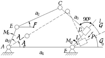
Fig.1 represents five link mechanism configuration having all revolute joints except one slider on output link. Notations shown in Fig.1 are applied throughout the study. The hybrid mechanism has an adjustable link designed to include a power screw mechanism for converting rotary motion to linear motion by means of a small slider. The slider is assumed to move on a frictionless plane.
The crank is driven by a DC motor (the main motor) through a reduction gearbox; the slider is driven by a lead screw coupled the second servomotor (the assist motor).
Here the main motor is applied as a constant speed motor, and the constant speed motor profile is applied. Point-to-point positioning is certainly achieved for both motors, and the system output is taken from the last link.
a1, a2, a3, a4 link lengths of the mechanism (m)
φ,θ, ϕ,ψ angular displacement of the links (rad)
φ&,θ&, ϕ&,ψ& angular velocity of the links (rad/s)
φ&&,θ&&, ϕ&&,ψ&& angular acceleration of the links (rad/s2)
L L
L,&, && displacement, velocity, and acceleration of the slider on output link (m, m/s, m/s2)
P the assist driving force (N) M0 the main driving torque (Nm)
ψ
M drag torque on output link (Nm)
i i Y
X , positions to the mass centre of the links in fixed coordinates(m)
1
γ the engaging angle of main drive for C point in Fig.1 (degree)
2
γ the engaging angle of assist drive for C point in Fig.1 (degree)
Ⅲ.KINEMATICS ANALYSIS OF THE CONTROLLABLE MECHANISM
Kinematics analysis of five bar linkage is needed before carrying out derivations for the mathematical model. The mechanism is shown with its position vectors in Fig. 1. The output of system is dependent on two separate motor inputs and the geometry of five bar mechanism. Referring to Fig. 1, the output is given by ψ , and the configuration represents in-line mechanism. The output motion profiles ψ , ψ&, ψ&&can be designed for the
system as ψ ,ψ& , ψ&&.
In general, the model of a mechanical system can simply be considered as inertial rigid system. Simplifying assumptions are required while developing the mathematical model. Friction and clearance in all joints are neglected. The mechanism operates in vertical plane and gravity effects are included.
Since the hybrid five-bar mechanism has two degrees of freedom (φ, L) in Fig. 1, equation (1) and (2) is found as below.
dL L d d
∂ ∂ + ∂ ∂
= φ ψ
φ ψ
ψ (1)
or
2
1 ψ
ψ
ψ d d
d = + (2)
where dψ1,dψ2are tiny displacement of output link caused
solely by the main motion dφ and the assist motion dL
respectively.
If friction losses in all joints and the change in the kinetic energy are neglected, we can obtain
0
0dφ+PdL+Mψdψ =
M (3)
90º
ψ
M
M0
d
b e
θ
a
l
A B
C
E D
ψ
0
ψ
φ L P
φ
0
Figure 1. Schematic diagram of controllable five link mechanism. c
a1
a2
a3
Since both dφ and dL are independent variables, M0 and P can be obtained from (1) and (3),
φ ψ
ψ ∂∂
−
= M
M0 (4)
L M P ∂ ∂ −
= ψ ψ (5) By referring to Fig. 1, the loop closure equation is written as:
ED AE CD BC
AB+ + = + (6)
By solving vector loop equation (6), angular positions of the link b and c are obtained. Having found the angular displacements of each linkage asθ, and ϕ in the five bar linkage, time derivatives can be taken to find angular velocity and accelerations. Some partial derivatives also can be found. They are definitely needed during the analysis of dynamic model. We can obtain
0 2 1 22 32 22
2+ K L+K +K −a =
L (7)
Where
) cos(
)
cos( 0 1 0 0
4
1=a ψ +ψ −a ψ +ψ −φ−φ
K
) cos( )
sin( 0 1 0
3 4
2 =a −a ψ +ψ −a φ+φ
K
) sin( )
cos( 0 1 0
3
3=a ψ +ψ −a φ+φ
K
0 2 1 4
1 a (a a )cosφ
A = − +
0 2 1
1 (a a )sinφ
B = +
3 1 2 3 2 1 2 1 1 0 2arctan
a B a B A A + − + + = ψ
Therefore, we have
2 3 2 2 2 2 2 1
1 K a K K
K
L=− + + − − (8)
L L&,&&,
L ∂ ∂ψ and φ ψ ∂ ∂
can be found from (8)
3 3 6 1 K a LK K L L + + = ∂ ∂ψ 1 3 6 4 3 5 0 4
1( sin( ) )
K a LK K a LK a a + − − + = φ φ ∂φ ∂ψ where )) ( )
cos(( 0 0
4 = ψ +ψ − φ+φ
K
)) ( )
sin(( 0 0
5 = ψ +ψ − φ+φ
K
5 1 0 4
6 a sin( ) aK
K = ψ +ψ −
Angular positions of link a2 and a3 are
) cos( ) sin( arctan 0 2 0 3 ψ ψ ψ ψ θ + + + + = L K L K (9) 0 3
2π ψ ψ
ϕ= + + (10)
Thus, we can get θ&,θ&&, φ θ ∂ ∂ , L ∂ ∂θ
from (9), and ϕ&=ψ& ,
ψ
ϕ&&= && from (10).
According to the geometrical relationship of linkage in Fig. 1, the expressions of Xiand Yi(the positions to the
mass centre of each links in fixed coordinates) can be easily obtained as follows:
) sin( )
cos(φ+φ0 − φ+φ0
= y
a x
a
a S S
X
) cos( )
sin(φ+φ0 + φ+φ0
= y
a x
a
a S S
Y
θ θ
φ
φ ) cos sin
cos( 0 1 y b x b
b a S S
X = + + −
θ θ
φ
φ ) sin cos
sin( 0 1 y b x b
b a S S
Y = + + +
) cos( ) sin( ) cos( 0 0 0 4 ψ ψ ψ ψ ψ ψ + − + − + + = y e y e c S S L a X ) sin( ) cos( )
sin(ψ +ψ0 + ψ +ψ0 − ψ +ψ0
= y
e y
e
c L S S
Y
) sin( )
cos( 0 0
4+ ψ +ψ − ψ+ψ
= y
l x
l
l a S S
X
) cos( )
sin(ψ+ψ0 − ψ +ψ0
= y
l x
l
l S S
Y
By using the equations of XiandYi, we can getX&&i,Y&&i,
φ ∂
∂Xi
, L Xi ∂ ∂ , φ ∂
∂Yi
and L Yi ∂ ∂ ) 4 3 2 1
(i= , ,, one by one.
Ⅳ. MATHEMATICAL MODEL OF OPTIMAL DESIGN FOR CONTROLLABLE MECHANISM
A. Design Variables
Hybrid mechanism can be determined by selecting a design vector as follows:
x [x,x ,x ,x ]T
4 3 2 1
= (11)
where, 4 0
4 3 3 4 2 2 4 1
1= = = ,x =φ
a a ,x a a ,x a a
x ,a4 =1.
B. Objective Functions
The problem of determining mechanism dimensions can be expressed as a constrained optimization problem.
In order to ensure the smaller adjustment for the assist motion under constraint functions, objective functions can be designed respectively as follows.
Model 1:
minf1 =Lmax−Lmin (12)
Model 2:
min f2=max
2 ) ( ψ M P
− =max
Model 3:
min f3=max
2
) d d (
φ
ψ L
L ⋅ ∂ ∂
=max )2
d d (
φ ψ φ ψ
∂ ∂
− (14)
C. Constraint Functions
These functions consist of inequality constraints with stand type according to MATLAB optimization toolbox. They are functions of design variables.
(1) Inequality constraint related to the movable condition of controllable mechanism
To ensure existence of the controllable five-bar mechanism, the follow inequality constraints are to be satisfied.
a1+a4−a2− a32+L2 <0
2 4 0
2 2 3
1+ a +L −a −a <
a
a1+a2− a32+L2 −a4<0
min( 4) 0
2 2 3 2
1− a , a +L ,a <
a
(15) (2) Inequality constraint due to the engaging angle
Taking into account simultaneous existence of main and assist motion, the engaging angle of the controllable mechanism correlates with actual velocity direction and trend of C point in Fig. 1. The engaging angles can be obtained by taking velocity synthesis for the main and assist motion at C point, or substituting vector synthesis of tiny displacement (at C point) caused solely by the main and assist motion into (8).
To ensure existence of the engaging angle, two constraints are obtained from the engaging angles of the main and assist motion:
0 ] [
1 − γ ≤
γ tan
tan
max
0 ] [
2 − γ ≤
γ tan
tan
max
(16)
where
) )( d d d d ( ) (
d d
) )(
d d d d ( ) ( d d
tan
6 3
3 6
3 6 3
1 1
L K a
L a K L
a K a
L L K L
+ −
− −
− −
+ + =
φ ψ φ
φ
ψ φ
ψ φ
φ ψ
γ
φ ψ φ
φ ψ γ
d d d
d d d
tan
3 2
a L
L
− =
where
[ ]
γ is allowable transmission angle of mechanism.Ⅴ. HYBRID OPTIMIZATION ALGORITHM
Swarm intelligence is an emerging field of biologically-inspired artificial intelligence based on the behavioral models of social insects such as ants, bees, wasps and termites. This approach utilizes simple and flexible agents that form a collective intelligence as a group. Since 1990s, swarm intelligence has already become the new research focus and swarm-like algorithms, such as PSO, have already been applied successfully to solve real-world optimization problems in engineering and telecommunication. The PSO algorithm does not use the filtering operation (such as crossover and mutation) and the members of the entire population are maintained through the search procedure. This article employs a hybrid optimization algorithm which combines Particle Swarm Optimization (PSO) with MATLAB Optimization Toolbox to find optimum solutions for the dimensional design problem with constraint condition of the controllable mechanisms.
A. Particle Swarm Optimization
PSO simulate social behavior, in which a population of individuals exists. These individuals (also called “particles”) are “evolved” by cooperation and competition among the individuals themselves through generations [12, 13, 14]. In PSO, each potential solution is assigned a randomized velocity, are “flown” through the problem space. Each particle adjusts its flying according to its own flying experience and its companions’ flying experience. The ith particle is represented as Xi =(xi1,xi2,K,xiD) . Each particle is treated as a point in a D-dimensional space. The best previous position (the best fitness value is called pBest) of any particle is recorded and represented as
) , , ,
( i1 i2 id
i p p p
P = K . Anther “best” value (called gBest) is recorded by all the particles in the population.
This location is represented as Pg =(pg1,pg2,K,pgD). At each time step, the rate of the position changing velocity (accelerating) for the ith particle is represented asVi=(vi1,vi2,K,viD). Each particle moves toward its pBest and gBest locations. The performance of each particle is measured according to a fitness function, which is related to the problem to be solved. The particles are manipulated according to the following equation:
) (
) (
) (
) (
2 1
id gd
id id id
id
x p Rand c
x p rand c v w v
− ⋅ ⋅
+
− ⋅ ⋅
+ ⋅ =
(17)
xid =xid +vid (18)
where c1and c2 in (17) are two positive constants, which
represent the weighting of the stochastic acceleration terms that pull each particle toward pBest and gBest positions. Low values allow particles to roam far from the target regions befor being tugged back. On the other hand, high values cause abrupt movement toward, or past, target regions. Proper values of c1 and c2 can quicken
functions in the range [0, 1]. The use of the inertia weight w provides a balance between global and local exploration, and results in less iteration to find an optimal solution.
B. Parameters Setting
Main parameters of PSO are set as follows. (1) The inertia parameter
The inertial parameter w is introduced to control the impact of the previous history of velocities on current velocity. A larger inertia weight facilitates global optimization while smaller inertia weight facilitates local optimization. In this paper, the inertia weight ranges in a decreasing way in an adaptive way. The inertia weight is obtained by the following equation:
iter Iter
W W W
W = − max− min ⋅
max (19)
Where Wmax: the maximum value of W min
W : the minimum value of W
Iter: the maximum iteration number of PSO iter: current iteration number of PSO (2) The parameters c1and c2
The acceleration constants c1 and c2 control the
maximum step size the particle can do, they are set to 2 according to experiences of other researchers.
C. Search Algorithm Hybridization
Being a global search method, the PSO algorithm is expected to give its best results if it is augmented with a local search method that is responsible for fine search. The PSO algorithm is hybridized with a gradient based search. The ‘‘candidate’’ solution found by the PSO algorithm at each iteration step is used as an initial solution to commence a gradient-based search using ‘‘fmincon’’ function in MATLAB [15], which based on the interior-reflective Newton method. The ‘‘fmincon’’ function can solve the constraint problem here.
D. Hybrid Optimization Algorithm
The procedure of hybrid optimiziation algorithm is shown as follows.
Step1. Initialize V and X of each particle. Step2. Calculate the fitness of each particle.
Step3. If the fitness value is better than the best fitness value (pBest) in history, set current value as the new pBest.
Step4. Choose the particle with the best fitness value of all the particles as the gBest .
Step5. Calculate particle velocity according (17), update particle position according (18).
Step6. Let the above solution as an initial solution, and carry out a gradient-based search using ‘‘fmincon’’ function in MATLAB Optimization Toolbox. Step7. When the number of maximum iterations or
minimum error criteria is attained, the particle with the best fitness value in X is the approximate solution and STOP; otherwise let iter=iter+1 and turn to Step 2. Where iter denotes the current iteration number.
Particles’ velocities on each dimension are clamped to a maximum velocity vBmaxB, If the sum of accelerations
would cause the velocity on that dimension to exceed vBmax,
which is a parameter specified by the user. Then the velocity on that dimension is limited to vBmaxB.
Ⅵ.NUMERICAL EXAMPLES
Initial values of design varibles can be obtained with link lengths of link and angle φ0 in Table 1. These link
lengths and angle values for the controllable five bar mechanism in the studies of optimal kinematics design were obtained by Wang [16]. The output motion profile is designed as a sine acceleration law.
( )
(
)
⎪ ⎪ ⎩ ⎪ ⎪ ⎨ ⎧
⎟ ⎠ ⎞ ⎜
⎝
⎛ − − −
⋅ −
⎟ ⎠ ⎞ ⎜
⎝ ⎛ − ⋅ =
π φ π π
π φ
φ π π φ ψ
2 2 2
1 2 2
1
sin H
H
sin
H
(
)
(
π φ π)
π φ
2 0
≤ ≤
≤ ≤
(20)
where H=64o =16π/45.
We choose [γ ] = 45°, kinematics and performance parameters obtained for the controllable five link mechanism in this studies of optimal kinematics design are shown in Table 2 (by using MATLAB Optimization Toolbox), and Table 3 (by using hybrid optimization algorithm).
For kinematics performance index of the mechanism, we choose the actuator manipulability indexμ[17],
det( T)
μ = J J⋅ , (21)
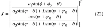
where matrix J is known as the kinematic Jacobian matrix. Most of the measures of kinematic performance of linkage mechanism are based on the kinematic Jacobian matrix. According to kinematics analysis of controllable five bar actuator in Fig. 1, the Jacobian matrix can be found as follows (Intermediate steps for the kinematic Jacobian matrix analysis can be seen in Appendix)
T
L a
L a
a
⎥ ⎥ ⎥ ⎥
⎦ ⎤
⎢ ⎢ ⎢ ⎢
⎣ ⎡
− + +
−
−
+ + −
+ −
− +
=
) sin(
) sin(
) cos(
) sin(
) sin(
) sin(
0 3
0 0 3
0 1
θ ψ ψ θ
ϕ
θ ψ
ψ ψ ψ θ
θ ϕ
θ φ φ
J (22)
and Fig. 3, the results obtained by using the third optimal objective function (Model 3) are to be satisfied.
In order to test validity of the hybrid optimization algorithm, we perform optimization design by using different optimization methods. The manipulability indexμof optimization design from Matlab Optimization Box and the PSO algorithm are provided respectively in Fig. 4. Here, equation (14) is chosen as objective function. As shown in Fig. 4, the comparison shows that the global optimum solution of optimization design of the controllable five bar mechanism using hybrid optimization algorithm proposed can be obtained.
Figure 4. The manipulability index of the controllable five bar mechanism by using different optimization methods.
Figure 3. Control curves of the assistant motion.
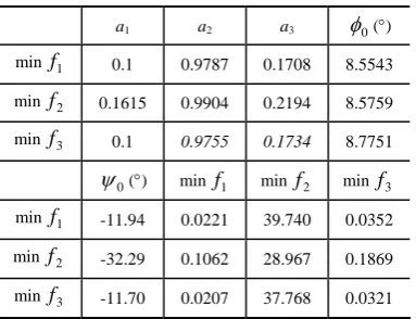
TABLE III.
THE RESULTSOF OPTIMIZATION DESIGNBY USING HYBRID
OPTIMIZATION ALGORITHM
a1 a2 a3 φ0(°)
min f1 0.1 0.9787 0.1708 8.5543 min f2 0.1615 0.9904 0.2194 8.5759 min f3 0.1 0.9755 0.1734 8.7751
0
ψ (°) min f1 minf2 minf3
min f1 -11.94 0.0221 39.740 0.0352
min f2 -32.29 0.1062 28.967 0.1869 min f3 -11.70 0.0207 37.768 0.0321
TABLE II.
THE RESULTS OF OPTIMIZATION DESIGNBY USING MATLAB
OPTIMIZATION TOOLBOX
a1 a2 a3 φ0(°)
min f1 0.1 0.9767 0.1728 8.5563
min f2 0.1645 0.9904 0.2194 8.5749
min f3 0.1 0.9755 0.1734 8.77413
0
ψ (°) min f1 minf2 minf3
min f1 -11.876 0.0221 39.680 0.0348 min f2 -32.093 0.1154 28.995 0.1842 min f3 -11.587 0.0198 37.578 0.0317
TABLE I.
INITIAL VALUE OF THE PLANAR PARALLEL CONTROLLABLE
MECHANISM
a1 a2 a3 φ0(°)
Initial
values 0.1319 0.9424 0.1 13.146
Ⅶ.CONCLUSIONS
This paper has described theoretical investigation of a planar parallel controllable mechanism with its kinematics. The method of kinematics analysis and design for the controllable mechanism is proposed on the basis of geometric configuration of the controllable mechanism and hybrid optimization algorithm. Making use of the method, an optimal kinematics design for a controllable five bar mechanism is given in this paper. As a result of the comparisons, better performances have been obtained in terms of kinematics objective functions. Optimal kinematics design is more propitious to the applied effects of assist motion control and the development of controllable mechanism.
APPENDIX A
Referring to Fig.1, set θ1= +φ φ0, θ2=θ , θ3=ϕ ,
andθ4= +ψ ψ0. Let θ5is angular displacement of the
AE link (rad). Complex number expression of the vector equation (6) can be written as follows:
5 4 3 2 1 4 i i 3 2 1 θ θ θ θ
θ i i
i e a Le e a e a e
a + = + +
(23)
Differentiating (23) with respect to time t, we can obtain (24), 4 4 3 2 1 4 3 3 2 2 1
1θ θ θ θ θ θ θ θ θ
j j j j j e L je L je a je a je
a & + & = & + & + & (24)
Multiply both sides of (24) by
e
−iθ2) ( ) ( 4 ) ( 3 3 2 2 ) ( 1 1 2 4 2 4 2 3 2 1 θ θ θ θ θ θ θ θ θ θ θ θ − − − − + + = + j j j j e L je L je a j a je a & & & & & (25)
Imaginary parts in both sides of (25) is equal each other, then ) sin( ) cos( ) cos( ) cos( 2 4 2 4 4 2 3 3 3 2 2 2 1 1 1 θ θ θ θ θ θ θ θ θ θ θ θ − + − + − = + − L L a a a & & & & & (26) Set 2 1 12 a a
k = ,
2 3 32
a a
k = ,
2 42
a L
k = , and
2 01
1
a
k = . Then,
) cos( ) sin( )) cos( ) cos( ( 2 1 1 12 2 4 4 01 4 2 4 42 2 3 32 2 θ θ θ θ θ θ θ θ θ θ θ − − − + − + − = & & & & k a k k k (27)
Real parts in both sides of (25) is equal each other, then (28) can be gotten
) cos( ) sin( ) sin( ) sin( 2 4 2 4 4 2 3 3 3 2 1 1 1 θ θ θ θ θ θ θ θ θ θ θ − + − − − − = − − L L a a & & & & (28)
From (28), we have
) sin( ) sin( ) cos( ) sin( 2 4 2 3 3 2 4 2 1 1 1
4 θ θ θ θ
θ θ θ θ θ θ − + − − + − = L a L a & &
& (29)
Equation (29) also can write in vector form, namely,
⎥ ⎦ ⎤ ⎢ ⎣ ⎡ = L& & & φ
ψ J (30)
So, we can obtain the kinematic Jacobian matrix of the mechanism as follows.
T L a L a a ⎥ ⎥ ⎥ ⎥ ⎦ ⎤ ⎢ ⎢ ⎢ ⎢ ⎣ ⎡ − + − − − + − − = ) sin( ) sin( ) cos( ) sin( ) sin( ) sin( 2 4 2 3 3 2 4 2 4 2 3 3 2 1 1 θ θ θ θ θ θ θ θ θ θ θ θ
J (31)
Namely, T L a L a a ⎥ ⎥ ⎥ ⎥ ⎦ ⎤ ⎢ ⎢ ⎢ ⎢ ⎣ ⎡ − + + − − + + − + − − + = θ) sin( ) sin( ) cos( ) sin( ) sin( ) sin( 0 3 0 0 3 0 1 ψ ψ θ ϕ θ ψ ψ ψ ψ θ θ ϕ θ φ φ J ACKNOWLEDGMENTS
The work is supported partially by Science Fund of Shanghai Institute of Technology (Grant No.YJ2006-09). We would like to express our gratitude to all those who gave us help to complete this paper, especially for Dr. Yongxing Wang of Donghua University whose constructive suggestions help us in all the time of research and writing of this paper.
REFERENCES
[1] L. C. Tokuz, J. R. Jones, Hybrid Machine Modelling and Control. Ph.D. Thesis, Liverpool Polytechnic, 1992. [2] A. M. Conner, The Synthesis of Hybrid Mechanism Using
Genetic Algorithm. Ph.D. Thesis, Livepool John Moores University, 1996.
[3] J. D. Greenough, W. K. Bradshaw, and M. J. Gilmartin, “Design of hybrid machines,” Proceedings of 9th World Congress on the Theory of Machines and Mechanisms, vol. 4 , pp. 2501-2505, 1995.
[4] A. Kireçci, L. C. Dülger, “A Study on a Hybrid Actuator,”
Mechanism and Machine Theory, vol. 35, no. 8, pp. 1141-1149, 2000.
[5] L. C. Dülger, A. Kireçci, and M. Topalbekiroglu, “Modelling and Simulation of Hybrid Actuator,”
Mechanism and Machine Theory, vol. 38, no. 3, pp. 395-407, 2003.
[6] P. R. Ouyang, Q. Li, W. J. Zhang, and L. S. Guo, “Design, modeling and control of a hybrid machine system,”
Mechatronics, vol. 14, pp. 1197-1217, 2004.
[7] S. R. Singiresu, Engineering Optimization. John Wiley & Sons, New York, 1996.
[9] J. Kennedy, R. Eberhart, “Particle Swarm Optimization,”
Proceedings of IEEE International Conference on Neural Networks, pp. 1942-1948, 1995.
[10]R. Eberhart, Y. Shi, “Tracking and optimizing dynamic systems with particle swarms,” Proceedings of the IEEE Congress on Evolutionary Computation, pp. 94–97, 2001. [11]I. C. Trelea, “The particle swarm optimization algorithm:
convergence analysis and parameter selection,”
Information Processing Letters, vol. 6, pp. 317–325, 2003. [12]J. Kennedy, C. Eberhart, R. Shi, and Y. Swarm, Swarm
Intelligence, Morgan Kaufmann, San Mateo, CA, 2001. [13]M. Clerc, J. Kennedy, “The particle swarm-explosion
stability and convergence in a multidimensional complex space,” IEEE Transaction on Evolutionary Computation,
vol. 6, no. 1, pp. 58-73, 2002.
[14]H. Yoshida, K. Kawata, Y. Fukuyama, and Y. Nakanishi, “A particle swarm optimization for reactive power and voltage control considering voltage stability,” Proceedings International Conference on Intelligent System Application to Power Systems, pp. 117-121, 1999.
[15]A. Grace, Optimization Toolbox For Use with Matlab, User’s Guide. Math Works Inc., 1994.
[16]S. Z. Wang, Y. J. Shen, and Cheng Zhang, “Dynamics Analysis and Design for a Variable Structure Genealized linkage,” China Mechanical Engineering, vol. 13, no. 2, pp. 245-248, 2002. (in Chinese)
[17]T. Yoshikawa, “Manipulability of Robotic Mechanism,”
International Journal of Robotic Research, vol. 4, no. 2, pp. 3-9, 1985.
Ke Zhang, born in 1968, received M.Sc degree in Mechanical Manufacture and Automatization from College of Mechanical Engineering of Xi’an Jiaotong University, China, in 1999, and PhD degree in Mechanical Design and Theory from Donghua University, China, in 2005, respectively. Now he joins School of Mechanical Engineering, Shanghai Institute of Technology as a professor, and is engaged in the study as mechanical measurement technology, mechanical optimization design, controllable mechanism system, complex machine dynamics, and mechanism-electric control. In these areas, he has published over fifty technical papers in refereed journals or international conference proceedings (IEEE, ASME). He took part in three projects of National Natural Science Foundation of China.
Shengze Wang, born in 1957, received the PhD degrees in Signal & Information Processing from Huanzhong University of Science and Technology, China, in 1994 and join College of Mechanical Engineering of Donghua University as a professor at present. His main research interests include mechanical dynamics, controllable mechanism, mechanical system model, textile machine and mechanical measurement technology. In these areas, he has published over 30 technical papers in refereed journals or international conference proceedings. He took charge of two projects of National Natural Science Foundation of China