Automatic Test Cases Generation for Statechart
Specifications from Semantics to Algorithm
Lina Chen
College of Mathematics Physics and Information Engineering, Zhejiang Normal University Jinhua, China E-mail: [email protected]
Abstract—This paper studies automatic test cases
generation for Statechart specifications. Applying Tretmans’ approach to generate test cases from labeled transition systems, we provide a solid mathematical basis for conformance testing and automatic test case generation for Statechart specifications. In order to make the test cases generation process more simple and efficient, we propose observable semantics as a suitable semantics model for describing observable behavior subset of a Statechart specification, which is different from complete semantics used for Statechart specification verification and model checking. Then we describe how to use this semantics model for not only generation reactive systems but also critical reactive systems. We also propose a formal conformance relation based on presented semantics model and test hypothesis, and provide an algorithm which, for a Statechart specification, generates a test suite. For Statechart specifications with graph semantics the algorithm can generate complete test suite, and for Statechart specifications with tree semantics cost-efficient sound test suite can be generated.
Index Terms—Statechart; Specification; Implementation;
Conformance Testing; Test Suite; Test Cases Generation; Formal Semantics; Reactive Systems
I. INTRODUCTION
Testing is an important activity for checking the conformance of system implementation to system specification by means of test experiments. Traditionally, test cases are manually developed based on some informal, natural language description of the system specification. Because the natural language specifications often lead to ambiguities and misinterpretations about the system's required properties, such a test cases generation process is laborious and error-prone. Then automation of test cases generation seems a logical solution. In order to automate test cases generation, using formal specification language to specify target system is unavoidable. Formal specifications are concerned with mathematical modeling of systems. Due to their mathematical underpinning formal specification languages allow to specify systems with more precision, more consistency and less ambiguity. Test cases can be efficiently, effectively and systematically derived from the formal specifications. There are many formal languages, e.g., CCS, CSP, ACP, LOTOS, SDL, Z, PROMELA and Statechart can be used to obtain
formal system specifications. In this paper we consider Statechart language and set the theoretical basis for automatic test cases generation for Statechart specifications.
We base our work on Tretmans’ foundational research on test case generation from labeled transition systems, which is also called conformance testing theory.
Broadly speaking, conformance testing refers to a field of theory, methodology and applications for testing that a given implementation of a system conforms to its abstract specification. Its main points can be summarized as follows:
1. Using formal semantics, system specification can be mapped into a mathematical structure.
2. Using test hypothesis, system implementation can also be mapped into a mathematical structure. 3. Conformance relation, also called implementation
relation, is formally defined between above two formal objects.
4. Test suite is defined based on conformance
relation.
5. Test cases generation algorithm is designed based on conformance relation and test suite definition. An account of the major results in the area of conformance testing and conformance relations in the context of labeled transition systems (LTSs) can be found in [1-4]. However, to our knowledge, the study of conformance relations and testing theory in general, in the context of Statechart, has received scant attention, and the most important and systematic research work is done by D. Latella, S. Gnesi and their colleagues in [5-8]. In their approach, both specifications and implementations are modeled as input output labeled transition systems (IOLTSs). They proposed a formal conformance relation and provide an algorithm which, for a Statechart specification and the alphabet of implementations, generates a test suite. The algorithm is proven exhaustive and sound w.r.t. the conformance relation.
When we apply their approach in practice, we find following problems.
experiment, testers apply environmental inputs to the implementation, observe its outputs and conclude whether the implementation conforms to the specification. Thus the semantics model used for test case generation need only specify testers observable behavior and conceal unobservable behavior of Statechart specifications, so that the test cases derived consists only testers observable inputs and outputs.
But in [8] the adopted IOTLS semantics is extended from the semantics model presented in [5], which is used for verification, and it covers all possible behavior of Statechart specifications. Because IOTLS semantics dose not distinguish observable behavior from unobservable behavior, the test cases generated from it include many useless information, which make the test generation process and test execution process less efficient, especially for complex reactive systems. We will review this problem in section 4 more detailedly.
2. Although each individual test case is finite long, typically test suite generated from IOLTS semantics is an infinite set. With infinite test suite the generation algorithm presented in [8] is proved to be complete. But a test suite with infinite number of test cases is unreasonable for practical use.
In the light of their work, to automate test cases generation for Statechart specifications, we should define suitable semantics model, which should only specify testers observable behavior and conceal unobservable behavior, and propose more reasonable test suite definition and practical test generation algorithm. The following sections address these problems detailedly.
II. STATECHARTSPECIFICATION
Statechart was introduced by David Harel in 1987 [9] as a visual specification language for complex reactive systems [10]: event-driven systems which continuously react to external stimuli. Over the years, a number of variants of Harel Statechart have been proposed – RSML [11], ROOM [12] and UML [13], to name a few. They retain the Harel Statechart structuring mechanism of hierarchy and group transitions, but differ significantly in semantic aspects, which make them more powerful for specific applications.
In this section, we propose out Statechart notation, which keeps the main aspects of most commonly used Statechart notations related to concurrency and state hierarchy, inter-level transitions, transition priority, broadcast communication; but events are restricted to input and output events, without parameters, and variables and data are not considered so that actions can only generate events. This sound “basic” kernel Statechart notation can be used to produce clear and mathematically analyzable sps. We give such a Statechart specification in Figure1.
s0
s7 c/d s8 s6 a/b
s2 m/q
u/v s3 s1
s4
s5
s9 f /g
s11 e/f s12
s10 b/c g/h s13
m/n x/y
Figure. 1 A Statechart specification example
A formal syntax definition of a Statechart specification is given as follows.
Definition 1. A Statechart specification is a 8-tuple
(S, LI, LO, s0, T, D, g, h) where S is a finite set including all possible Statechart states; LI is an inside inputs/outputs set; LO is an environmental inputs/outputs set; s0 is the root Statechart state; T
⊆
S × L × L × S (L=LI∪LO) is a finite set including all transitions; D is a set including all default active state of all OR states; g: S->2^S is a simple decomposite function; h: S->2^S is a parallel decomposite function; g and h are defined as follows:⎩ ⎨ ⎧ = ∈
∀
state OR a is s if s}, of substates {all
state OR a not is s if {s}, ) s ( g S
s ,
⎩ ⎨ ⎧ = ∈
∀
state AND a is s if s}, of substates {all
state AND a not is s if {s}, ) s ( h S
s ,
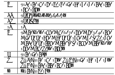
The formal syntax definition of the Statechart specification in Fig.1 is shown in table 1.
TABLE 1 EIGHT-TUPLE DESCRIPTION OF STATECHART MODEL EXAMPLE
S {s0, s1, s2, s3, s4, s5, s6, s7, s8, s9, s10, s11,
s12, s13}
LO {a,d,e,h,m,q,n,u,v,x,y} LI {b,c,f,g}
s0 s0
T {<s1, m, q, s2>, <s2, x, y, s3>, <s3, u, v, s1>, <s6, a, b, s7>, <s7, c, d, s8>, <s8, f, g, s9>, <s10, b, c, s11>, <s11, e, f, s12>, <s11, m, n, s3>, <s12, g, h, s13>}
D {s1, s6, s10}
g g(s0)={s1, s2, s3}, g(s4)={s6, s7, s8, s9},
g(s5)={s10, s11, s12, s13}
h h(s1)={s4, s5}
III.COMPLETESEMANTICSANDOBSERVABLE
SEMANTICS
Central to the problem of automatic test cases generation for Statechart specifications is their semantics. To efficiently automate test cases generation, we need to define a different semantics, which only considers testers observable behavior and conceal unobservable behavior of Statechart specifications. It is a compact semantics compared to above complete semantics.
Statechart specification is an IOLTS OS=(Λ, L, σ,
M-step) where Λ
⊆
2^S is a finite set including all observable global states; σ is the initial observable global state, σ∈Λ; L is environmental input and output set; M-step⊆
Λ× L × L ×Λ is a set including all possible observable global state transitions, also called M-step transitions.Every M-step transition starts from an observable global state in Λ, reacts to an environmental input by performing a sequence of reactions (called steps). At each step, a maximal conflict free set of enabled Statechart transitions is selected and executed based on events generated in the previous step. After completion of the last step there is no enable Statechart transition, then the IOLTS stop at another observable global state in . So M-step transitions are different from m-step transitions. They are only triggered by environment inputs, consists of several Statechart transitions, and produce only environment outputs.
While all inside inputs and outputs live for one step, environmental input is consulted only at the first step and environmental outputs are communicated to the environment after completion of the last step in a M-step. Usually, M-step transitions are executed infinitely fast, with the clock being incremented only at M-step transition boundaries. The observable semantics for the Statechart specification in Figure1 is shown in Figure2.
s6 s10
a/{d} s8
s11
e/{h} s9
s13
s2 s3 x/{y}
u/{v} m/{n}
m/{q} m/{q}
Figure2. An Observable Semantics for Statechart specification in
Figure1
A. Observable Semantics Generation Algorithm
Some of the general principles we have adopted in generating the observable semantics for a Statechart specification are the following:
1. In a M-step transition the system reacts to outside inputs by performing a sequence of steps.
2. At each step, a maximal conflict free set of enabled Statechart transitions are selected based on events generated in the previous step and executed in an unspecified order. The execution of a step itself takes zero time.
3. All inputs and outputs are broadcast to all Statechart transitions. While all inside inputs and outputs live for one step, environmental input is consulted only at the first step and environmental outputs are communicated to the environment after completion of the last step in a M-step.
According definition 2, the observable semantics is an IOLTS OS, so the most important thing for
observable semantics generation is to generate all
M-step transitions. The following algorithm is the M-step transition generation algorithm. In this algorithm we use set C’ to include all simultaneously active Statechart states, set I to include all inside inputs and outputs, set O to include all environmental outputs, and set Substate(p) to denote all directly or transitively nested substates of Statechart state p.
Algorithm 1 (M-step-generation)
Input to the algorithm is the Statechart specification (S, LI, LO, s0, T, D, g, h), an observable global state C containing the current simultaneously active Statechart states and the environmental input i.
Output of the algorithm is <C, i, O, C’>, a M-step transition from C to C’ labeled with environmental input i and environmental outputs O.
1.Initialization:
a. I<= Ø,O<= Ø,C’<= C。
2.Given environmental input i, find all enabled Statechart transitions:
a.D={<p,a,b,q> | <p,a,b,q>∈T, p∈C’ ∨ Substate (p)∩C’≠Ø, and a=i }.
b.If D= Ø, return error, else goto 3.
3.Select a maximal set of conflict free enabled transitions:
a.Every t1, t2∈D
a) If t1 and t2 are in conflict and Priority(t1) > Priority(t2)
b) Remove t2 from D
4.Execute all transitions in D in an unspecified order: a.Every Statechart transition <p,a,b,q> in D
a) If <p,a,b,q> is a same-level transition,
i. Use function g and h to remove p and Substate(p) from C’,
ii. C’<= C’ U {q}.
iii. If b is inside output, I<=I U {b}, else O<=O U {b}.
b) If <p,a,b,q> is a cross-level transition, the rewrite names of p and q is as shown in Fig.4.
i. Compute the right-most same element,
denoted by r, in the rewrite names of p and q (there must be such a r, at least r=s0). pi+1 is the element next to r for p and qj+1 is the element next to r for q.
ii. Use function g and h remove pi+1 and
Substate(pi+1) (including p) from C’, iii. Put all concurrent states with Statechart states
q0…qj+1, q0…qj+2, …, q0…qm-1 into C’,
iv. C’<= C’ U {q},
v. If b is inside output, I<=I U {b}, else O<=O U {b}.
5.Stabilization:
a.For every composite Statechart state in C’, a)If it is a AND state, use set D, function g and h
to substitute it by their substate;
b.D={<p,a,b,q> | <p,a,b,q>∈T, p∈C’ ∨ Substate (p)∩C’≠ Ø, and a=i }.
c.If D= Ø, return <C, i, O, C’>, else goto 4.
p0=s0, p1, p2, ……, pi=r, pi+1, ……,pn-1,pn
q0=s0, q1, q2, ……, qj=r, qj+1, ……,qm-1,qm
Figure3 name pattern for p and q
Using above M-step-generation algorithm, we propose an observable semantics generation algorithm. This algorithm uses a set B to record all the produced M-step transition, set C to include all simultaneously active Statechart states, and a stack to record all possible M-step transitions from observable global states.
Algorithm 2 (OS-generation)
Input to the algorithm is the Statechart specification (S, LI, LO, s0, T, D, g, h).
Output of the algorithm is an observable semantics ( , LO, σ, M-step).
1.Initialization:
a.C<={s0}, <=Ø, M-step<=Ø, B<=Ø, Empty(stack).
2.Obtain first/initial observable global state: a.For every composite Statechart state in C,
a)If it is a AND state, use set D, function g and h to substitute it by their substate;
b)If it is a OR state, use set D, function g and h to substitute it by their default active substate. b.σ<=C;
c.S<=S∪{C}.
3.Find all possible M-step transitions:
a.EO={i | <p,i,*,q>∈T, p∈C ∨ Substate (p)∩C≠Ø, and i∈LO }.
b.For every i in EO,
a)If <i,C>!∈B, then push <i,C> onto stack. 4.Generate M-step transitions and state space:
a.If stack is empty, a)stop.
b.Else
a)Pop stack top into <i,C>, b)B<= B∪{<i,C >},
c)Use SC, C and i to call M-step-generation algorithm, return <C, i, O, C’>.
d)S<=S∪{C’},
e)M-step= M-step∪{<C, i, O, C’>}, f)C<=C’,
g)goto 3.
An example may prove illuminating. We show the application of the proposed algorithm to the Statechart specification in Figure1 as follows.
1.C<={s0}; Obtain first observable state
C<={s6,s10}, σ<={s6,s10},S<=S∪{{s6,s10}}. 2.Push {s6,s10},m}; Push {{s6,s10},a}.
3.Pop {{s6,s10},a}; Execute <s6, a, b, s7>,<s10, b, c, s11>,<s7, c, d, s8> in order and obtain C’<={s8,s11},O<={d}; S<=S∪{{s8,s11}}, M-step=M-step∪{<{ s6,s10}, a, {d}, {s8,s11}>}. 4.Push {{s8,s11},e}; Push{{s8,s11},m}.
5.Pop {{s8,s11},m}; Compute D={<s8, m, n, s2>, <s1, m, q, s2>}; Priority(<s1, m, q, s2>)< Priority(<s8, m, n, s2>), remove <s1, m, q, s2>; Execute <s8, m, n, s2> and obtain C’ <={s2},
O<={n}; S<=S∪{{s2}}, M-step=
M-step∪{<{s8,s11}, m, {n}, {s2}>}. 6.Push {{s2},x}};
7.Pop {{s2},x}}; Execute <s2, x, y, s3> and obtain C’ <={s3}, O<={y}; S<=S∪{{s3}}, M-step= M-step∪{<{s2}, x, {y}, {s3}>}.
8.Push { s3},u }};
9.Pop {{s3},u }}; Execute <s3, u, v, s1> and obtain C’ <={ s6,s10}, O<={v}; S<=S∪{{ s6,s10}}, M-step= M-step∪{<{s3}, u, {v}, { s6,s10}>}. 10. Pop {{s8,s11},e }; Execute <s11, e, f,
s12>,<s8, f, g, s9>,<s12, g, h, s13> in order and obtain C’<={s9,s13},O<={h}; S<=S∪{{s9,s13}}, M-step=M-step∪{<{s8,s11}, e, {h}, {s9,s13}>}. 11. Push {{s9,s13},m };
12. Pop {{s9,s13},m }; Execute <s1, m, q, s2> and obtain C’ <={ s2}, O<={q}; S<=S∪{{ s2}}, M-step= M-step∪{<{s9,s13}, m, {q}, {s2}>}. 13. Pop {{s6,s10},m }; Execute<s1, m, q, s2>
and obtain C’<={s2},O<={q}; S<=S∪{{s2}}, M-step=M-step∪{<{s6,s10}, m, {q}, {s2}>}. 14. At last, we obtain the observable semantics
for the Statechart specification in Fig.1 as shown
in Fig.3. OS =
({{s6,s10},{s8,s11},{s9,s13},{s3},{s2}}, {a, d, e, h, m, q, n, x, y, u, v}, {s6, s10}, {({s6,s10},a,{d},{s8,s11}),
({s6,s10},m,{q},{s2}), ({s8,s11},e,{h},{s9,s13}), ({s8,s11},m,{n},{s2}), ({s9,s13},m,{q},{s2}), ({s2},x,{y},{s3}), ({s3},u,{v},{s6,s10}) } )。
Figure.4 is the COS for the Statechart specification in Figure.1
s6
s10 s11s8 s13s9
s2 s3
!(a|m)/rej ect !(e|m)/rej ect !m/rej ect
!u/rej ect !u/rej ect
a/{d} e/{h}
m/{q} m/{n} m/{q}
x/{y} u/{v}
Figure4 Critical Observable Semantics for Statechart specification in Figure1
IV.AUTOMATICTESTCASESGENERATION
A. Conformance testing and the conformance
relation
implementation, that is, a device or program interacting with its environment, which is considered as a black box. Test cases are derived from the specification, and applied to the implementation, such that from the results of applying them it can be concluded whether the implementation conforms to the specification.
In this paper we will consider as the test hypothesis that also implementations could be described as an IOLTS IS=(Σ’, LO, σ’, M-step’). Thus the test
hypothesis allows us to reason about implementations as if they were IOLTSs. Having specifications and implementations the next important thing is to define what it means for an implementation to conform to a specification, otherwise no useful test case can ever be generated. Conformance is defined by means of an conformance/implementation relation between the models of implementations and the specifications [1,8].
In this paper, a conformance relation “conforms-to” between specification IOLTS OS and implementation IOLTS IS is defined as follows.
Definition 3. Given an IOLTS S=(S, L, σ, step), α is
a finite sequence over L*, α= a1a2…an. We define function output: S->L* as follows:
output(S, α) =On,if there are <σ, a1, O1, p1>,<p1,
a2, O2, p2>,…<pn-1, an, On, pn>∈step; = Ø,
otherwise.
Definition4. Given specification IOLTS OS and
implementation IOLTS IS, OS conforms-to IS =def
every α∈LO*,output(OS, α)≠Ø => output(OS, α) =
output(IS, α).
In above definition, it is not explicitly described that what output(IS, α) is when output(OS, α)=Ø. From the
OS and COS generation algorithm we obtain following conclusions:
For every α∈L*, output(COS, α)≠Ø. So the
conformance relation for critical applications systems is for all possible behavior.There may be some α L*, output(OS, α)=Ø. So the conformance relation for
general application systems is for part of possible behavior.
B. Test Suite
We know that the implementation process is to build a real system based on the design specification. Normally we expect that OS=IS. But implementation is a human activity, and human is error prone, so bugs are unavoidable in developed systems, especially those are complex and often beyond human understanding. It is these bugs that make the difference between OS and IS. So we need test cases and test suites.
A test case is a specification of the behaviour of a tester in an experiment to be carried out with the implementation under test and the behavior of the implementation exhibited to the tester. An experiment should last for a finite time, so a test case should have finite behaviour. Moreover, a tester executing a test case would like to have as much control as possible over the testing process, so nondeterminism in a test case is undesirable. Formally, test case can be defined as follows:
Definition 5. Given an OS=(Σ, LO, σ, M-step), a test
case γ is a finite sequence over (LO×2^LO)*,
γ=(i1,O1)(i2,O2)…(ij,Oj)…(in,On), and there are where <σ, i1, O1, p1>,<p1, i2, O2, p2>,…, <pj-1, ij, Oj, pj>,…, <pn-1, in, On, pn>∈M-step.
In a test experiment of test case γ, tester, by hand or tools, applies every environment input ij of (ij,Oj) in γ
in order to the implementation under test, and observe the outputs of the implementation to check if they are the same as Oj of (ij,Oj) in γ, If they are same, the implementation passes this test case, otherwise, it fails to pass this test case.
Definition 6. For specification IOLTS OS=(Σ, LO, σ,
M-step) and implementation IOLTS IS=(Σ, LO, σ’, M-step’), given a test case γ=(i1,O1) (i2,O2)…(in,On),
IS passes γ if and only if <σ, i1, O1, p1>,<p1, i2, O2,
p2>,…, <pj-1, ij, Oj, pj>,…, <pn-1, in, On, pn>∈
M-step’.
With the difference in the M-step relation of observable semantics, we can divide all observable semantics into two disjoint groups: tree observable semantics and graph observable semantics.
Given an IOLTS S=(S, L, σ, step), we define relation
“→” over S×S as follows:
1.if<p, i, O, q>step, p→q; 2.if p→q, q→v, then p→v.
Definition 7. Given an OS=(Σ, LO, σ, M-step), OS is
a tree OS iff every p,q∈Σ and p≠q, p→q and q→p can
not hold simultaneously.
It is obvious that the M-step relation of a tree OS has
a tree shape. With the definition of test case, we can directly obtain following conclusion:
Tree OS has finite number of test cases.
Definition 8. Given an OS=(Σ, LO, σ, M-step), OS is
a graph OS iff there exist two p,q∈Σ and p≠q, p→q
and q→p hold simultaneously.
It is obvious that the M-step relation of a graph OS
has loop(s). With the definition of test case, we can directly obtain following conclusion:Graph OS has infinite number of test cases.
A test suite is a set of test case. According the difference in testing power, we define two test suite classes: complete test suite and sound test suite.
Definition 9. Given a specification with observable
semantics OS and an implementation IOLTS IS, a test suite is complete if
TS conforms-to IS <=> IS passes the test suite
It is obvious that for any possible implementation IS
complete test suite can check if it is conformance to its Statechart specification with observable semantics OS.
With the definition of conform relation “conforms-to” and the definition of test case, we can obtain following conclusion:
distinguished exactly. But for a graph OS, complete test suites have infinite number of test cases and is difficult to be used in practice. So we need a weaker class of test suites, which is called sound test suite.
A test suite is sound if all correct implementations, and possibly some incorrect implementations, will pass them; or, in other words, any detected erroneous implementation is indeed non-conforming, but not the other way around. Soundness corresponds to the left-to-right implication of completeness.
Definition 10. Given a specification with observable
semantics OS and an implementation IOLTS IS, a test suite is sound if
TS conforms-to IS => IS passes the test suite
With the definition of conform relation “conforms-to” and the definition of test case, we can obtain following conclusion: A sound test suite consists of any finite set of test cases of OS.
It is a minimal, formal requirement on test suites in order to be able to draw any useful conclusion from any testing campaign.
It is worth to notice that only a few general OS are tree OS, such as OS in Figure3, and all COS and most general OS are graph OS, such as OS in Figure2. So as stated by E.W. Dijkstra “testing can be used to show the presence of bugs, but never to show their absence”.
C. Test Suite generation algorithm
Now, of course, an important activity is to devise an algorithm, which produces a test suite from a Statechart specification given above implementation relation. This activity is known as test derivation.
There are two goals for the test suite generation: 1.For tree OS, the generation algorithm must
generate complete test suite,
2.For graph OS, the generation algorithm should generate sound test suite. But a sound test suite may be any finite set of test cases of the OS, so the algorithm must generate
cost-efficient sound test suite, i.e., on the one hand, it is small enough so that tester can use it; on the other hand, it can detect enough bad implementations so that tester will use it. The data structure using in the test suite generation algorithm is described as follows:
1. Queue Q, P consists of a serial of step transition. 2. Array A record the head address of all active
queues.
3. Array B record the head address of all useful queues.
Algorithm 2 (TS-generation)
Input to the algorithm is the observable semantics (Σ, LO, σ, M-step).
Output of the algorithm is a test suite.
1. For every transition with starting state σ in M-step: <σ,i,O,p>
a. Create queue Q, insert <σ,i,O,p> at tail of Q, record Q in A and B.
2. If A is empty, goto 5. Else goto 3.
3. Retrieve any queue Q from A, obtain its tail element<p,i,O,q>.
a. For every tansition with starting state q in M-step: <q,i,O,u>,
i. Create queue P, copy content from Q to P, insert <q,i,O,u> at tail of P.
ii. If P already has a same transition <q,i,O,u>, record P in B,
iii. Else record P in A and B. b. Delete Q from A and B. 4. Goto 2.
5. For every queue Q in B,
a.For every transition <q,i,O,u> in Q b.Replace <q,i,O,u> with <i,O>. 6. Return B.
An example may again prove illuminating. The following text contains the beginning portions of test suite generated from OS in Figure4.
!a|m/reject, !a|m/reject.
!a|m/reject, a/{d}, !e|m/reject, !e|m/reject,
!a|m/reject, a/{d}, !e|m/reject, e/{h}, !m/reject, !m/reject,
!a|m/reject, a/{d}, !e|m/reject, e/{h}, !m/reject, m/{q}, !x/reject, !x/reject,
!a|m/reject, a/{d}, !e|m/reject, e/{h}, !m/reject, m/{q}, !x/reject, x/{y}, !u/reject, !u/reject,
!a|m/reject, a/{d}, !e|m/reject, e/{h}, !m/reject, m/{q}, !x/reject, x/{y}, !u/reject, u/{v}, !a|m/reject, !a|m/reject, a/{d}, !e|m/reject, e/{h}, !m/reject, m/{q}, !x/reject, x/{y}, !u/reject, u/{v}, a/{d} …….
Because above test suite generation algorithm is a graph traverse algorithm, we can directly obtain following conclusions:
For tree OS, the generated test suites are complete test suites.
For graph OS, the generated test suites are sound test suites.
Because that there are no multiple occurrence of same input-output pair in every test case, the generated sound test suite is cost efficient.It is worth to notice that testers always adopt random testing technique, i.e., randomly choose some (<<|L|) of environment outputs of L/{x} to apply to implementation when they execute (!x, reject) in test case.
V. CONCLUSIONSANDFURTHERWORK
critical application systems.
We also propose a formal conformance relation based on observable semantics and test hypothesis and provide an algorithm which, for a Statechart specification, generates a test suite. For tree OS the algorithm can generate complete test suite, and for graph OS cost-efficient sound test suite can be
generated.Our further work is to automate the whole test process, not only test cases generation but also test execution, and to develop a prototypical automatic testing system that collaborates with commercial test execution tools.The architecture of this prototypical system is shown in Figure5.
Fr ont - end
t ool dat a f i l e anal ysi ssynt ax semant i csanal ysi s t est sui t egener at i on sci r pt
t est execut i on
t ool scr i pt
t r ansf or m
FTCL
Figure5 the Architecture of Automatic Testing System
The self-developed tool FTCL work as follows: 1. Retrieve Statechart specification data file
generated from front-end tool, such as Rose Statechart file or RhapSody Statechart file; 2. Produce standard Statechart syntax structure
(S, I, O, s0, T, D, g, h) from data file by syntax transformation;
3. Use observable semantics generation algorithm to generate ( , LO, σ, M-step);
4. Use test suite generation algorithm to generate test suite;
5. Transform the generated test suite into
acceptable input script of commercial test tools (such as Rational Robot, Visual Test, SilkTest, QARUN, etc.), then use these tools to automate test execution.
Another line of future research deals with the extension of the subset of Statechart notation we take into consideration, such as the introduction of data values and variables.
REFERENCES
[1] J. Tretmans: Test Generation with Inputs, Outputs and Repetitive Quiescence [J]. Software - Concepts and Tools. 1996, 17(3): 103-120.
[2] J. Tretmans. Testing concurrent systems: A formal approach [J]. LNCS, 1999, 1664:46–65.
[3] J. Tretmans, Conformance Testing with Labelled Transition Systems: Implementation Relations and Test Generation [J]. Computer Networks and ISDN Systems, 1996, 29(1):49-79.
[4] Brinksma and J. Tretmans, Testing Transition Systems: An Annotated Bibliography [J]. LNCS, 2001, 2067:187-195.
[5] Latella, I. Majzik, and M. Massink. Towards a formal operational semantics of UML statechart diagrams [A].
Proceedings of FMOODS'99 [C]. Florence, Italy, 1999, 331-347,.
[6] D. Latella and M. Massink. A formal testing framework for UML Statechart Diagrams behaviours: From theory to automatic verification [A]. Proceedings of Sixth IEEE International High-Assurance Systems Engineering Symposium [C]. 2001, 11–22.
[7] D. Latella and M. Massink. On testing and conformance relations of UML Statechart Diagrams Behaviours [A]. Proceedings of the ACM SIGSOFT 2002 International Symposium on Software Testing and Analysis [C]. 2002.144–153.
[8] S. Gnesi, D. Latella, and M. Massink. Formal test-case generation for UML statecharts [A]. Proceedings of ICECCS [C]. 2004. 75-84.
[9] D. Harel. Statecharts: A Visual Formalism for Complex Systems [J]. Science of Computer Programming, 1987, 8(3): 231-274.
[10] D. Harel and A. Pnueli. On the development of reactive systems [J]. Logic and Model of Concurrent Systems, 1984, F-13: 477–498.
[11] N.G. Leveson, etc. Requirements specification for process control systems [J]. IEEE Transactionson Software Engineering, 1994, 20(9):684-707
[12] Selic, G. Gullekson, and P.T.Ward. Real-Time Object-OrientedModeling [M]. John Wiley & Sons, 1994.
[13] Booch, J. Rumbaugh, and I. Jacobson. The Unified Modeling Language User Guide [M]. Addison-Wesley, 1998.
Lina Chen was born on 1978 in Jilin Province, China. Software engineering master, graduated from East China Normal University in 2006. And major field of study is signal processing and trusted computing.