e- ISSN: 2278-067X, p-ISSN: 2278-800X, www.ijerd.com
Volume 14, Issue 10 (October 2018), PP.13-22
Effect of Ceramic Proppant Surface Wettability on Oil Flow
Efficiency in Hydraulic-Fractured Wells
Kanjicai Dong
Department of Petroleum Engineering University of Louisiana at Lafayette, Lafayette, Louisiana, United State
ABSTRACT:
Ceramic proppants are key products for enhancing oil and gas well productivity in low-permeability reservoirs. However, they are not all created equal in size, material, and surface properties. The effects of proppant size and materials on oil and gas well productivity have been well studied in the past, but the role of proppant surface property in the performance improvement of oil and gas wells has not been thoroughly investigated. Nine experiments were conducted in this study to investigate the effect of wettability of ceramic proppant on the oil flow efficiency from core samples to “fractures” filled with the proppant in this study. Result of this shows that oil-wet ceramic proppant promotes oil flow efficiency from sandstone core samples to proppant packs and thus should promote oil well productivity. The mechanism behind this phenomenon is believed to be the formation of oil flow channels across the fracture face due to the imbibition of oil in the core onto the oil-wet surface of the proppant, promoting oil flow from the core to the fracture. Oil-wet proppant is more effective in improving oil flow efficiency in low-water saturation cores than in high-water saturation cores. Using larger size of oil-wet proppant helps improve oil flow efficiency. This may be explained by the more significant effect of adhesion/affinity of oil to the narrow corners of the solid surface in large-size proppant packs.--- --- Date of Submission: 16-01-2019 Date of acceptance: 28-01-2019 ---
I.
INTRODUCTION
Ceramic proppants are key products for enhancing oil and gas well productivity in low-permeability reservoirs. However they are not all created equal in size, material, and surface properties (Saldungaray and Palisch, 2013). The effects of proppant size and materials on oil and gas well productivity have been well studied in the past (Economides and Nolte, 2000; Vincent, 2002;Liang et al., 2015). However the role of proppant surface property in the performance improvement of oil and gas wells has not been thoroughly investigated. The key surface property of ceramic proppant affecting fluid flow efficiency is the wetting behavior which is often quantified by a parameter called contact angle measured in the wetting phase. In a water-oil system a solid surface is called strongly water-wet if the contact is approach 0 and strongly oil-wet if the contact angle is approach 180 degrees. A contact angle of around 90 degrees implies an intermediate wetting condition. A solid surface made of both water-wet and oil-wet materials is called mixed-wet surface.
The effect of solid surface wettability on oil recovery efficiency form oil reservoir was first investigated in late 1969’s and early 1970’s. Donaldson et al. (1969) demonstrated that water breakthrough and oil recovery from waterflood depend on core sample wettability.Anderson (1986a, 1986b, 1986c, 1987a, 1987b)presented a series of literature survey that summarizes the effects of wettability on fluid flow in porous media. It was pointed out that wettability affects relative permeability by controlling the flow and spatial distribution of fluids in a porous medium. In uniformlywetted systems, the effective oil permeability ata given initial water saturation decreases as the wettability is variedfrom water-wet to oil-wet. In fractionally wetted sandpacks, where the size of the individualwater- and oil-wet surfaces are on the order of a single pore,relative permeabilities appear to be similar to those in uniformlywetted systems. Wang (1988) found that during waterflood, a strongly water-wet core ceases to produce oil as soon as water breaks through, while a mixed-wettability core continuously produces oil for many PV’s, resulting in a very low residual oil saturation.Dubey et al. (1991) investigated wettability alteration due to asphaltene adsorption and desorption from mineral surfaces. Humphry et al. (2014) analyzed the impact of wettability on residual oil saturation and capillary desaturation.Abdallah et al. (2017) presents a thorough review onapplications of wettability concept in oil field.
flow efficiency in low and high water-saturation conditions.
II.
EXPERIMENTS
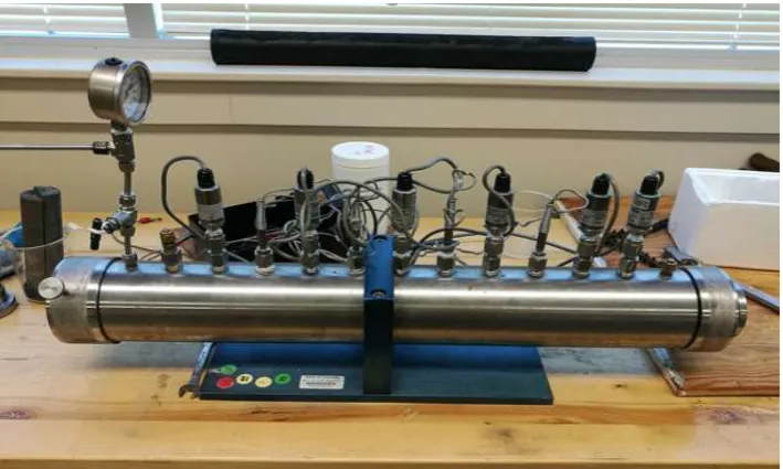
Test Apparatus.Experimental investigations were carried out using a 2-foot long core holder assembly shown in Figure 1. A section of a 2-inch diameter core sample with a fracture is shown in the left side of the image. A rubber sleeve for sealing core samples is seen at the top of the image. A cut off drawing of the core holder with surrounding connections is presented in Figure 2. As shown in Figure 3, inside the core holder is a core sample with a slot cut and filled with proppants, simulating a propped fracture.
Test Procedure.The experimental procedure is outlined as follows: 1. Measure the dimension and dry weight of a sand stone core sample. 2. Remove the air in the core sample by vacuum in a water chamber. 3. Measure the wet weight of the core sample and determine its porosity.
4. Transfer the wet core sample into the core holder, seal the core with confining pressure, inject water through the core, and determine core permeability.
5. Inject oil into the core till desired residual water saturation is reached.
6. Remove the core sample from the core holderand cut a slot in the axial orientation of the core to simulate a hydraulic fracture.
7. Fill the slot with proppant, transfer the core sample into the core holder, and seal the core with confining pressure.
8. Inject water and oil with deignedwater cut through the coreand record water and oil flow rates at the outlet. 9. Stop fluid injection when the effluent water cut reaches the water cut at the inlet.
10. Analyze the effluent water cut data to determine oil flow efficiency.
Figure 2: A schematic drawing the of core holder with surrounding connections
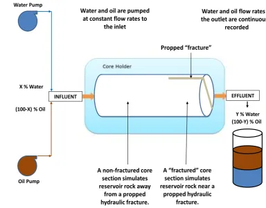
(100-Y) % Oil Y % Water
A “fractured” core section simulates reservoir rock near a
propped hydraulic fracture. A non-fractured core
section simulates reservoir rock away
from a propped hydraulic fracture. Water Pump
Oil Pump (100-X) % Oil
INFLUENT X % Water
EFFLUENT Water and oil are pumped
at constant flow rates to the inlet
Water and oil flow rates at the outlet are continuously
recorded
Propped “fracture”
Figure 3: A flow diagram to show water-oil 2-phase injection
Test Materials. The materials used in the experiments include: 1. Parker Berea sandstone cores
2. CC20/40 ―water-wet‖, 20/40 ―oil-wet‖, and SL12/18 ―oil-wet‖ proppants 3. 48~50o API gravity crude oil
(a) Water was absorbed by the proppant immediately, indicating water-wetting surface of the proppant.
(b) Some oil was absorbed by the proppant, indicating certain degree of oil-wetting behavior of the proppant surface.
Figure 4: Wettability check of the CC 20/40 “water-wet” proppant
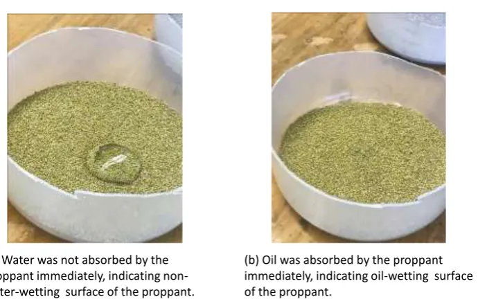
(a) Water was not absorbed by the proppant immediately, indicating non-water-wetting surface of the proppant.
(b) Oil was absorbed by the proppant immediately, indicating oil-wetting surface of the proppant.
(a) Water was not absorbed by the proppant immediately, indicating non-water-wetting surface of the proppant.
(b) Oil was absorbed by the proppant immediately, indicating oil-wetting surface of the proppant.
Figure 6: Wettability check of the SL12/18“oil-wet” proppant
Experimental Design.Nine experiments were designed to investigate oil flow efficiency in ceramic proppants of different sizes and wettability under low and high-water saturation ―reservoirs‖ conditions. They are:
1. CC 20/40 ―oil-wet‖ proppantwith 40% water-cut two-phase injection 2. CC 20/40 ―water-wet‖ proppant with 40% water-cut two-phase injection 3. CC 20/40 ―oil-wet‖ proppantwith 70% water-cut two-phase injection 4. CC 20/40 ―water-wet‖ proppant with 70% water-cut two-phase injection
5. CC 20/40 ―oil-wet‖ proppantwith oil injection followed by 40% water-cut two-phase injection 6. CC 20/40 ―water-wet‖ proppant with oil injectionfollowed by 40% water-cut two-phase injection 7. SL 12/18 ―oil-wet‖ proppant with oil injection followed by 40% water-cut two-phase injection 8. CC 20/40 ―oil-wet‖ proppantwith oil injection followed by 70% water-cut two-phase injection 9. CC 20/40 ―water-wet‖ proppantwith oil injectionfollowed by 70% water-cut two-phase injection
III.
RESULT
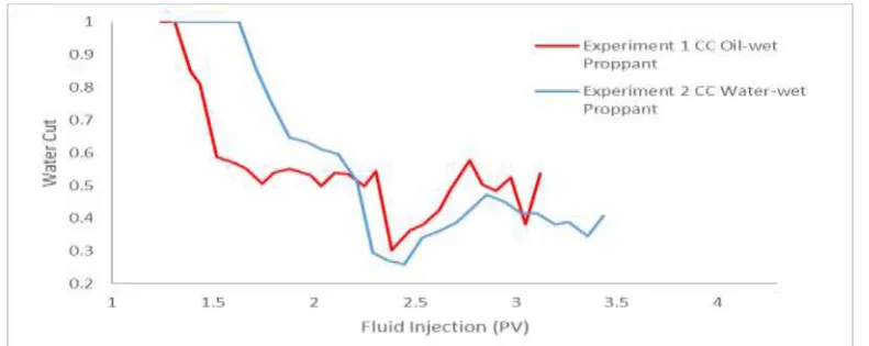
Experiment 1: 20/40 “Oil-Wet”Proppant with 40% Water-Cut Two-Phase Injection
reached the influent water cut. This implies that the ―oil-wet‖ proppant promoted oil flow and hindered water flow in low water-sturation conditions.
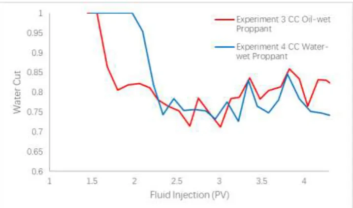
Experiment 3: 20/40 “Oil-Wet”Proppant with 70% Water-Cut Two-Phase Injection
This experiment was designed to investigate the oil flow efficiency in oil-wet proppant packs in high-water saturation oil reservoirs. A 22-inch long 2-inch diameter Parker Berea sand stone core was first tested to obtain porosity of 14.1% and water permeability of 12.99 md. A slot of 6-inch long and 0.15-inch wide was cut and filled with 21 grams of CC 20/40 ―oil-wet‖ proppant. The core was then transferred into the core holder and sealed with confining pressure. Water and oil were injected into the core sample at 7 ml/min of water and 3 ml/min of oil, i.e., the water cut in the influent is 70%. The received water and oil in the effluent were continuously monitored as the injection time went on. The effluent water cut data is plotted in Figure 8. It indicates that the water-cut in the effluent dropped quickly, fluctuated, and approached to the influent water cut of 70%.
Figure 8:Comparison of 20/40 “oil-wet” proppant and 20/40 water-wet proppant with 70% water cuttwo-phase injection
Experiment 4: 20/40 Water-Wet Proppant with 70% Water-Cut Two-Phase Injection
―water-wet‖ proppant in Experiment 4, before they reached the influent water cut. This implies that the ―oil-wet‖ proppant promoted oil flow and hindered water flow in high water-cut conditions.
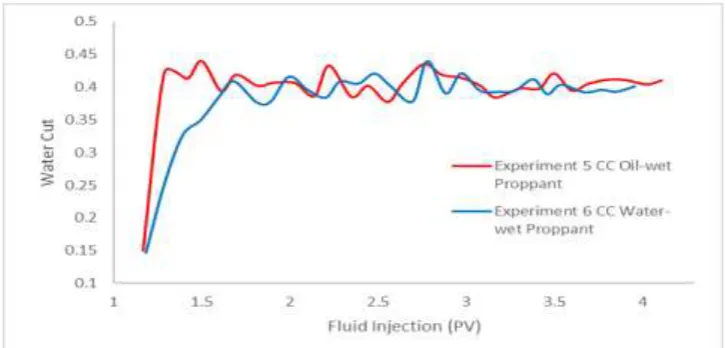
Experiment 5: 20/40 “Oil-Wet”Proppant withOil InjectionFollowed by40% Water-Cut Two-Phase Injection
This experiment was designed to investigate the oil flow efficiency in oil-wet proppant packs in virgin oil reservoirs at early time of water flooding. A 22-inch long 2-inch diameter Parker Berea sand stone core was first tested to obtain porosity of 13.1% and water permeability of 14.73md. A slot of 6-inch long and 0.15-inch wide was cut and filled with 21 grams of CC 20/40 ―oil-wet‖ proppant. The core was then transferred to the core holder and sealed with confining pressure. Oil was first injected into the core sample at 10 ml/min to achieve an initial water saturation of 0.3284. Water and oil were then injected into the core sample at 4 ml/min of water and 6 ml/min of oil, i.e., the water cut in the influent is 40%. The received water and oil in the effluent were continuously recorded as the injection time went on. The water cut in the effluent is plotted in Figure 9. It indicates that the water-cut in the effluent severely fluctuated. The reason is not known.
Experiment 6: 20/40 “Water-Wet”Proppant withOil InjectionFollowed by40% Water-Cut Two-Phase Injection
This experiment was designed to investigate the oil flow efficiency in water-wet proppant packs in virgin oil reservoirs at early time of water flooding. A 22-inch long 2-inch diameter Parker Berea sand stone core was first tested for porosity and permeability with water. The porosity and water permeability were found to be of 16.3% and14.67 md, respectively. The water-saturated core was cut a slot of 6-inch long and 0.10-inch wide and the slot was then filled with 26 grams of CC 20/40 ―water-wet‖ proppant. The core was then transferred to the core holder and sealed with confining pressure. Oil was first injected into the core sample at 10 ml/min to achieve an initial water saturation of 0.3223. Water and oil were injected into the core sample at 4 ml/min of water and 6 ml/min of oil, i.e., the water cut in the influent is 40%. The received water and oil in the effluent were continuously recorded as the injection time went on. The water cut data in the effluent is also plotted in Figure 9, which shows that the water-cut in the effluent slightly fluctuated around the influent water cut of 40%. A comparison of the two curves in Figure 9 indicates that the level of effluent water cut for the oil-wet proppant seems lower in average than that for the water-oil-wet proppant before they approach to the same influent water-cut 40%, meaning that the oil-wet proppant helps improve oil flow efficiency.
Figure 9:Comparison of 20/40 oil-wet proppant and 20/40 water-wet proppant with oil injectionfollowed by40% water Cuttwo-phase injection
Experiment 7: 12/18“Oil-Wet”Proppant withOil InjectionFollowed by40% Water-Cut Two-Phase Injection
Figure 10:Comparison SL 12/18“oil-wet” proppant and CC 20/40 “oil-wet” proppant with oil injectionfollowed by40% water cuttwo-phase injection
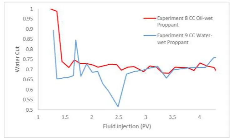
Experiment 8: 20/40 “Oil-Wet”Proppant withOil InjectionFollowed by70% Water-Cut Two-Phase Injection
This experiment was designed to investigate the oil flow efficiency in oil-wet proppant packs in virgin oil reservoirs at late time of water flooding. A 22-inch long 2-inch diameter Parker Berea sand stone core was first tested to obtain porosity of 15.7% and water permeability of 13.22 md. A slot of 6-inch long and 0.1-inch wide was cut and filled with 27 grams of CC 20/40 ―oil-wet‖ proppant. The core was then transferred to the core holder and sealed with confining pressure. Oil was first injected into the core sample at 10 ml/min to achieve an initial water saturation of 0.3210. Water and oil were then injected into the core sample at 7 ml/min of water and 3 ml/min of oil, i.e., the water cut in the influent is 70%. The received water and oil in the effluent were continuously recorded as the injection time went on. The water cut in the effluent is plotted in Figure 11. It indicates that the water-cut in the effluent dropped quickly and then gradually approached the influent water cut 70%.
Experiment 9: 20/40 “Water-Wet”Proppant withOil InjectionFollowed by70% Water-Cut Two-Phase Injection
This experiment was designed to investigate the oil flow efficiency in water-wet proppant packs in virgin oil reservoirs at late time of water flooding. A 22-inch long 2-inch diameter Parker Berea sand stone core was first tested for porosity and permeability with water. The porosity and water permeability were found to be of 16.1% and14.51 md, respectively. The water-saturated core was cut a slot of 6-inch long and 0.10-inch wide and the slot was then filled with 26 grams of CC 20/40 ―water-wet‖ proppant. The core was then transferred to the core holder and sealed with confining pressure. Oil was first injected into the core sample at 10 ml/min to achieve an initial water saturation of 0.3162 Water and oil were injected into the core sample at 7 ml/min of water and 3 ml/min of oil, i.e., the water cut in the influent is 70%. The received water and oil in the effluent were continuously recorded as the injection time went on. The water cut data in the effluent is also plotted in
Figure 11, which shows that the water-cut in the effluent fluctuated before reaching the influent water cut of 70%. A comparison of the two curves in Figure 11 indicates that the level of effluent water cut for the oil-wet proppant is similar to that for the water-wet proppant, meaning that the oil-wet proppant does not significantly improve oil flow efficiency in high water-saturation oil reservoirs.
IV.
DISCUSSION
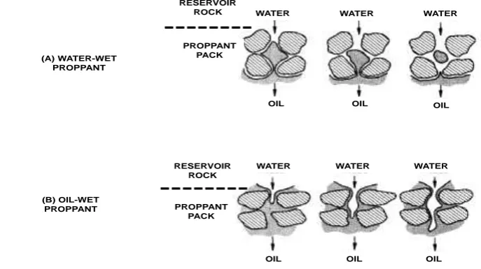
formation of oil flow channels across the fracture face due to the imbibition of oil in the core onto the oil-wet surface of the proppant, promoting oil flow from the core to the fracture.
2. Oil-wet proppant is more effective in improving oil flow efficiency in low-water saturation cores than in high-water saturation cores. The principle behind it is not clear and needs more in-depth investigations. 3. Using larger size of oil-wet proppant helps improve oil flow efficiency. This may be explained by the more
significant effect of adhesion/affinity of oil to the narrow corners of solid surface in small-size proppant packs.The mechanism is not clear and needs more in-depth investigations.
REFERENCES
[1]. Abdallah, W. and Buckley, J.S., and Carnegie, A.: Fundamentals of Wettability. Oil Field Review. Summer 2017: 44-61.
[2]. Anderson, W.G.: ―Wettability Literature Survey—Part 1: Rock/Oil/Brine Interactions and the Effects of Core Handling on Wettability,‖ Journal of Petroleum Technology, 38 (October 1986a): 1125–1144.
[3]. Anderson, W.G.: ―Wettability Literature Survey—Part 2: Wettability Measurement,‖ Journal of Petroleum Technology, 38 (November 1986b): 1246–1262.
[4]. Anderson, W.G.: ―Wettability Literature Survey—Part 3: The Effects of Wettability on the Electrical Properties of Porous Media,‖ Journal of Petroleum Technology, 38 (December 1986c): 1371–1378.
[5]. Anderson, W.G.: ―Wettability Literature Survey—Part 4: Effects of Wettability on Capillary Pressure,‖ Journal of Petroleum Technology, 39 (October 1987a): 1283–1300.
[6]. Anderson, W.G.: ―Wettability Literature Survey—Part 5: The Effects of Wettability on Relative Permeability,‖ Journal of Petroleum Technology, 39 (November 1987b):1453–1468.
[7]. Anderson, W.G.: ―Wettability Literature Survey—Part 6: The Effects of Wettability on Waterflooding,‖ Journal of Petroleum Technology, 39 (December 1987c): 1605–1622.
[8]. Bestaoui-Spurr, N.; Sun, S.; Williams, V.; Volk, A.; Nguyen, S.: Using Properties in Nature to Modify Proppant Surfaces and Increase Flow, SPE-184543-MS, SPE International Symposium on Oilfield Chemistry, Montgomery, TX, Apr-13-15, 2017. [9]. Bestaoui-Spurr, N., Langlinais, K., Stanley, D., Usie, M., & Li, C.: Controlling Proppant Wettability Leads to Increase Flowback
Recovery and Flow in Frac-Packs. SPE-184543-MS, SPE International Conference and Exhibition on Formation Damage Control. Lafayette, LA, February 2018.
[10]. Donaldson, E. C., Thomas, R. D., and Lorenz, P. B. 1969. Wettability determination and its effect on recovery efficiency. SPE J. March:13–20.
[11]. Dubey, S.T. and Waxman, M.H.: Asphaltene adsorption and desorption from mineral surfaces. SPERE (Aug. 1991) 389-395. [12]. Humphry, K. J., Suijkerbuijk, B. M. J. M. and van der Linde, H.A., Impact of Wettability on Residual Oil Saturation and Capillary
Desaturation Curves. Petrophysics, 55, 4 (August 2014): 313–318.
[13]. Economides, M. and Nolte, K. 2000. Reservoir Stimulation. United Kingdom: 3rd Ed Wiley and Sons Ltd.
[14]. Liang, F., Sayed, M., Al-Muntasheri, G.A., Chang, F.F., and Li, L. 2015. A Comprehensive Review on Proppant Technologies. Ke Ai, Petroleum 1 (2015) 1-14.
[15]. Mora, T., Orogbemi, O. A., And, Z., And Karpyn, T. 2010. A Study of Hydraulic Fracture Conductivity and Its Dependence on Proppant Wettability, Petroleum Science and Technology, 28:1527–1534.
[16]. Raza, S. H., Treiber, L. E., & Archer, D. L. (1968). Wettability of reservoir rocks and its evaluation. Prod. Mon.;(United States), 32(4).
[17]. Saldungaray, P. and Palisch, T. 2013. UnderstandingCeramic Proppants: Are They All Created Equal? Paper SPE 164042 presented at the SPE Middle East Unconventional Gas Conference and Exhibition held in Oman, 28-30 January 2013.
[18]. Vincent, M. C.: Proving It-A Review of 80 Published Field Studies Demonstrating the Importance of Increased Fracture Conductivity. SPE Annual Technical Conference and Exhibition. January 2002.
[19]. Wang, F.H.L. 1988. Effect of Wettability Alteration on Water/Oil Relative Permeability, Dispersion, and Flowable Saturation in Porous Media, SPE Reservoir Engineering. V. 3, No. 2,617-628.