ISSN (Online): 2320-9364, ISSN (Print): 2320-9356
www.ijres.org Volume 5 Issue 9 ǁ September. 2017 ǁ PP. 63-69
The radiation heat flow field analysis of water medium in Heating
Furnace
1
Li Ke Wang ,
*Yun Guo,
3Jiang YaZhou,
4GaoYuFei,
5YanHaoLi
(College of Mechanical Engineering, Shanghai University of Engineering Science, Shanghai 201620)Corresponding Author:Email :graceguo1980@126.com
ABSTRACT:
The fluent is a relatively versatile commercial software in the ansys of fluid software. It has some advantages such as convenient calculation, saving time and effort, good simulation effect, and can be mutually verified. It is widely used in energy and chemical industry. There are some problems in the practical application of Water jacket furnace , such as heating efficiency can’t be high, water jacket furnace combustion system life not long, water jacket fireworks system easy to corrode perforation leakage.In this article ,we at the point of how to improve the heating efficiency,and use the Fluent software to do the Simulation. To analyzed and compared the simulation results when heating medium use water and heat transfer oil respectively.Under the radiation model ,we will analysis of radiation and convective heat transfer which played a greater role with the standard . After do the simulation,we can get purpose of Energy saving , Emission reduction and improve the efficiency of Heating furnace.Keywords: fluent ; heat—transfermedium ; heating furnace; heat transfer efficiency; radiation heating
--- --- Date of Submission: 21-09-2017 Date of acceptance: 04-10-2017 ---
I.
INTRODUCTION
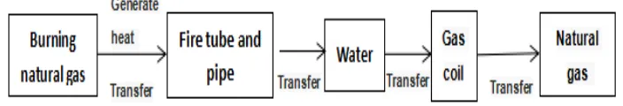
Here introduce the heating principle of heating furnace.firstly,the hot flame heating the pyrotechnic tube directly, then these smoke flows backwards, through the outlet pipe into the smoke box, finally by the chimney pumped into the atmosphere. But near the smoke and flue gas outlet pipe, medium water after being heated, the density becomes smaller and these water gradually rises. then after contact with the gas coil, the temperature decrease, and there water due to density increased and sink,then heated and rise.at last.Since then, go and return in following a circle.thereby the natural gas is heated in the gas coil,reach the purpose of increased the temperature of natural gas. it should be noted that gas within the gas pipe can not exceed the allowable working pressure.
e
Figure 1 Schematic diagram of heating
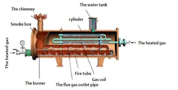
Figure 2 internal system structure of the furnace
So we assumption heating furnace has the same environment and boundary structure of the simulation process,the meshing and operating environment remain unchanged. analyze and compare the two kinds of different situation in the cylinder Internal,which one have better temperature field and flow field status.
1.Mathematical model
For ease of comparison, the same working conditions were used for water and heat transfer oil:
① using the same physical model: steady state, laminar flow, DO radiation model
② keep the same standard atmospheric pressure 101325pa.
③ working temperature are set to 348K.
④ sub-relaxation factors are consistent, Pressure is 0.3, Density is 1, Body Forces is 1, Momentun is 0.7, Energy is 1.
⑤ the initial temperature is set to 300K
⑥ Calculate the heat transfer coefficient with the same calculation formula The Reynolds number is calculated as follows:
Re
VD
VD
QD
v
vA
Nusselt number calculation:
For heating fluid:
0.8 0.4
0.023Re
(
)
f f f w f
Nu
pr
t
t
For cooling fluid:
Where Rf is the Reynolds number of the airflow in the convection tube and Pr is the Prandtl number.
Boundary condition calculation :
The heating gas flow rate is set at 1.67 m / s,the pressure of the heated gas is 5.5 MPa, and the inlet and outlet temperatures of the heated gas are 280 and 320 K respectively, It is assumed that the physical properties in the calculation process are constant. Due to the medium temperature change is small, so that the density and temperature are think have linear ratio. Fluid flow is considered to be steady-state laminar flow, so viscous dissipation is negligible. The cylindrical wall is considered to be adiabatic and its heat loss will be ignored while using the Boussinesq assumption which based on steady-state laminar flow conditions.
According to actual operating conditions of heating device, the boundary conditions are calculated as follows: the cylinder wall is regarded as adiabatic boundary; the average temperature of the fire pipe wall is set to 420K, the average temperature of the flue pipe bundle wall is set to 380K; The condition applies to the boundary of the convective tube bundle and expressed as:
)
(
Pr
Re
023
.
0
f0.8 f0.3t
wt
f(
)
w
e w g
T
k
h T
t
n
Where ke is the thermal conductivity of the heat transfer medium; n is the normal direction of the wall;
Tw is the wall temperature; Tg is the temperature of the heated gas. The average temperature of the heated gas in the first and second pipes was 290 K, and the average temperature of the heated gas in the third and fourth pipes was 310 K. h is calculated by the heat transfer coefficient:
·k
gNu
h
d
Where kg is the thermal conductivity of the gas in the convective tube bundle; d is the diameter of the
convection tube; and the Nusselt number (Nu) is calculated by the correlation.
And in the heating pipe inside the specific activities of the situation, the Reynolds number can be described
as:
- is the average flow rate (m / s),
- the diameter of the convection tube (m);
- is the hydrodynamic viscosity; - is the volume flow (m3 / s);
- is the cross-sectional area (m2);
u
- fluid velocity ;
- density kg/m3 ;p
- pressurePa
;
- kinematic viscosity m2/s
While the natural parameters of natural gas at 300 ° are: 300k
Density Kg/m3
constant-pressu re specific heat kJ/(m3·k)
Thermal conductivityw/( m·k) Dynamic viscosity Pa·s Pr
natural gas 889.8657 2.09 0.1136 1.23E-5 0.1458
300k
Gas flow rate m/s
Re Heat transfer coefficient
w/(m2·k) 1.51 415125.96 407.306
Through the parameters in the table can be obtained:
889.8657 1.51 0
415125.96
1.23
5
.038
Re
VD
E
Bring Re into formula (2) ,Prf =0.8329,
0.8 0.4 0.8 0.4
0.023Re
0.023 (415
125.96)
(
0.1
458
)
332.487
f f f
Nu
pr
2
·k
332.487 0.0391
=342.116
/
(
/
)
0.038
gNu
w
h
d
m
k
Calculation of water boundary conditions: 300k
Density Kg/m3
constant-pressure specific heat kJ/(m3·k)
Thermal conductivityw/(m ·k) Dynamic viscosity Pa·s Pr
natural gas 44.0822 4236.3575 0.0366 1.21E-5 0.843
300k
Gas flow rate m/s
Re Heat transfer coefficient w/(m2·k) 1.30 179971.957 331.07
Through the parameters in the table can be obtained:
44.0822 1.3 0.
179971.957
1.2
038
R
1
e
5
E
VD
Bring Re into formula (2) ,Prf =0.843,
0.8 0.4 0.8 0.4
179971.957
0.023Re
0
.023 (
)
(
0.8
43
)
343.734
f f f
Nu
pr
Bring Re into formula (2) ,Prf =0.843,
2
·k
343.734 0.0366
=331.07
(
/ )
0.038
/
g
Nu
w
h
d
m
k
II.
RESULTS ANALYSIS
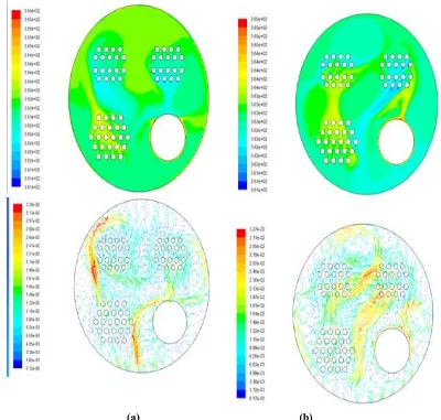
From the physical characteristics of the intermediate medium,Whether it has a good heat transfer and diversion properties,this is an important parameter in the assessment of intermediate media. The following we will analysis with the simulation results:
(a) (b)
Figure 3. Before rotating the temperature and speed of the flow field. (a) Isothermal contour (K); (b) flow vectogram (m/s).
interference factors are relatively large.
III.
CONTRAST ANALYSIS OF RADIATION
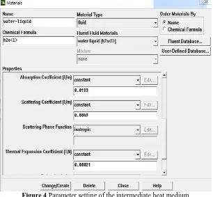
When the DO radiation model is turned on in Fluent,the emissivity will be selected to calculate the amount of radiation, which is the ratio that the object of the radiant capacity to the the blackbody of radiant capacity while them at the same temperature, It is a key parameter that determines the radiation between different media.the water emissivity is 0.96,and the amount of radiation is calculated as follows:
4 4
1 2
(
)
r m m
Q
A
T
T
εm is the emissivity of the medium, Am is the effective area of the medium involved in the radiation, and σ is the radiation constant of the blackbody.
Figure 4 Parameter setting of the intermediate heat medium
It can be seen from the figure that under the same working conditions, the amount of total heat transfer larger than no radiation. As the temperature increases, the trend decreases sharply. because the low boiling point of water, its work in high temperature conditions easy to cause heat loss.Before add radiation model,in the interior of furnace only natural convection play heating effect,the result of heating efficiency is not very satisfactory,while in radiation model,the natural convection and media participatory radiation work together,the heat transfer capacity of the furnace is greatly increased,the effect has been greatly improved, So it is necessary join the radiation model.
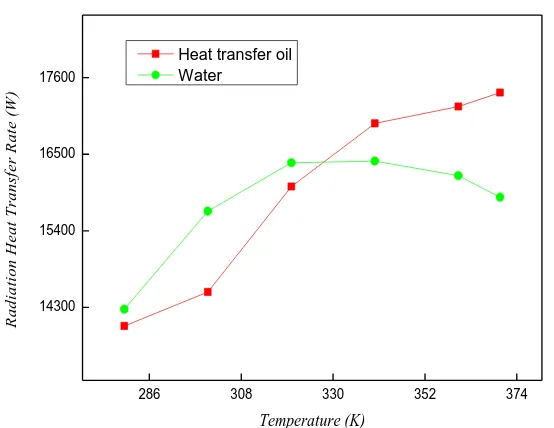
The radiation at each rotation is as follows:
Table 1 Water and heat transfer oil at different temperatures
280 300 320 340 360 400 heat
transfer oil
14632.342 15121.676 17135.342 17842.453 17985.567 18185.567
Figure 5 Comparison of the amount of radiation between the two media at different temperatures
It can be seen from the figure that under the same working conditions, the radiant quantity in the water is larger than that of oil when in low temperature . As the temperature increases, the amount of radiation of water decreases sharply,but the Heat transfer oil is opposite. according their physical properties, the water work in high temperature conditions easily gasification and can not conducive to heat transfer.,but the oil is different, in low temperature, the oil viscosity is relatively large, not good for to flow, the radiant quantity is relatively small, and can also avoid the problem of gasification. Therefore, the participant radiation effect of water is better than that of Heat transfer oil at low temperature. At high temperature, the participant radiation effect of Heat transfer oil is better than water .
IV.
CONCLUSIONS
(1)The heating medium based on the physical properties , according to the heating principle , we analysis the factors which influencing the heating efficiency , and at the viewpoint of economy and practicability, we propose how to improved the heating efficiency .
(2) Under the same radiation model, when the temperature is greater than 100 °, the thermal efficiency of Heat transfer oil is better than water. While the temperature is lower than 100 °, water is selected as the best heating medium. In the actual work, wu should according the actual situation, select the appropriate heat medium. Declaration of interest
The researcher declare that the manuscript have no competing interests including any financial, the personal, or organizations. and no conflicts with the study of any individual economic interests and non-economic interests and any direct or between obligation and responsibility. within three years of beginning the submitted work that could inappropriately influence, or be perceived to influence the present .As the researchers of this project, I economic interests above statement is true.
Acknowledgements
This research work was financially supported by National Natural Science Foundation of China (NFSC,51606116).
REFERENCES
[1]. Korea fluent fluid simulation calculation of engineering examples and application [D]. Beijing: Beijing university of science and technology press, 2008
[2]. Doroudi Shahed. ANSYS Fluent Modelling of the an Underexpanded Supersonic Sootblower Jet Impinging into Recovery Boiler Tube Geometries' [D], Canada: University of Toronto, 2015.
[3]. Yun Guo, CAOWei-wu, YANPing. Visualized experimental investigation on the natural gas heater[D], Canada: University of Toronto, 2015.
[4]. GengYangJie Liu Yuhuai etc. Based on FLUENT simulation of press ink roll cooling structure analysis and optimization [J]. 2016 01:165-169
[5]. Yun Guo,Zhixiong Guo.Flow and heat transfer inside a new diversion-type gas heating device[J],Taylor & Francis,2016:1-13.
286 308 330 352 374
14300 15400 16500 17600
R
a
d
ia
ti
o
n
H
e
a
t
T
ra
n
sf
e
r
R
a
te
(
W
)
Temperature (K) Heat transfer oil
Industry[J],Heat Transfer Engineering,2011(Vol32):1003-1008.
[7]. Ran Li, Fangjing Jia. Study on the Properties of Glazed Tiles Heated by the Low - Carbon Catalytic Combustion Furnace of Natural Gas [M]. California: Journal of Applied Mathematics and Physics, 2016 (Vol. 4) : 1455-1459.
[8]. a. n. Makarov. Calculations of Heat Transfer in the Torch Furnaces by Gas Volume Radiation Laws [M]. Russia: the World Journal of Engineering and Technology, 2016 (Vol. 4) : 488-503.
[9]. rui-jin wang. Fluent software technology foundation and application example. Beijing: tsinghua university press, 2007.
[10]. Faheemullah Shaikh. Evaluating China 's natural gas supply security -based on ecological network analysis [J]. Journal of Cleaner Production2016 (3) : 106.
[11]. Lai Xiangjun Dai Lin. Oil and gas - opportunities and challenges [M]. Beijing: chemical industry press, 2005.1.
[12]. the fields in the arts, the Xue Chao. Treasure - oil and gas fluid [M]. Beijing: petroleum industry press, 2002, 12.
[13]. hai-liang zhang, wet gas heating coil pipe wall fouling process model and the ability to predict [D]. Beijing: China university of petroleum, 2011
[14]. Meng Ju. Use and development of Shanghai city gas. Shanghai gas [J]. Shanghai: 2003, 2.
[15]. Peter, Franz. The genearation of steam by waste heat from furnaces [M]. Philadelphia: The American Institute of Mining, Engineers, 1913-6
[16]. Wang Zhongda, bevel gear based on thermal coupling flow field and temperature field simulation analysis [D], jilin, jilin university, 2015
[17]. i. v. Egorov, v. l. Zamyatin, The World Market for hold Heated Furnaces and Ovens [M], Icon Group International, Incorporated (nasdaq: PCLN - news), 2003.06
[18]. the loyal. New type heating furnace, micro positive pressure furnace [M]. Foreign oil field engineering, 2002 (4)
[19]. NiuBin. SC series multiwell gas heating furnace of environmental protection and energy saving analyses [M]. Petroleum machinery, 2003 (10)
[20]. qing-bo yu, Qin Qin etc. The improvement of water jacket furnace design [M]. Industrial heating, 2000 (6).
*Li Ke Wang . ―The radiation heat flow field analysis of water medium in Heating Furnace‖