automation of the KSU- BAE UGV’s is that there can be multiple drones can run once. Therefore, a central control station was needed to monitor the status of the controls and performance of the robots. This includes the location of the robot, the velocity, the function, and equipment monitoring (battery status, sensor functionality, motor performance, etc). The UGV’s will need to be able to wirelessly communicate its status through a wireless network from the UGV’s microcontrollers using slave-master wireless communication. Each of the KSU-BAE UGVs utilize Lab VIEW software and one National Instruments (NI) myRIO-1900. A Lab VIEW program was developed for the central command station, with messages transmitted at a maximum rate of 200Hz.
--- --- Date of Submission: 05-05-2018 Date of acceptance: 21-05-2018 --- ---
I.
INTRODUCTION
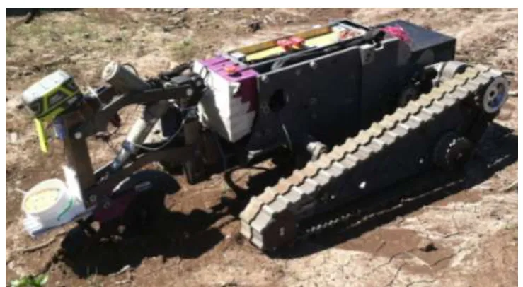
Figure 1: KSU- BAE UGV with a prototype planter sowing wheat seed.
II.
REVIEW OF LITERATURE
For the UGV’s to communicate, a wireless network protocol, a wireless network configuration, and a method of serial transmission need to be chosen. First, there are four common wireless communication protocols for wireless networks. They are Wi-Fi, ZigBeeNetworks,Bluetooth, and Cellular Networks. Wi-Fi is a communication protocol that uses a 2.4 GHz or a 5 GHz frequency band to create a wireless network using 802.11n standard(IEEE, 2009). Wi-Fi Networksallow for connected nodes to talk to each other, and to talk to a coordinator (the control system of the network), and are not difficult to set up. The main disadvantage of Wi-Fi is to get enough bandwidth over the drone operating area (i.e. agricultural fields) for effective communication between the drones and the central control station, and to have the power necessary to maintain a network over large distances. This may not be possible in some rural areas. Zigbee Networks are low powered, low-cost, device to device networks based upon the IEEE 802.15.4 standard (IEEE, 2016). The Zigbee Network contains three types of devices: a coordinator, a router, and an end device, and can be set up in star and mesh networks(ZigBee Alliance, 2013). DigiXBeeantennasuse a similar protocol to the Zigbee’s network to communicate wirelessly(Digi International Inc., 2017). DigiXBee antennas can communicate a long distance, and are relatively low in costs. Bluetooth is a wireless network that allows a coordinator to talk with up to seven nodes using Bluetooth 5.0 core specification. The main disadvantage for Bluetooth is that it is limited on distance (up to 150 meters) for coordinator to node communication(Bluetooth, 2016).A cellular network is a wireless network that is established with various protocols, including GSM, HSPA, and LTE, and operate at a variety of frequencies. Typical operating range from 35km to 200km from a central signal transmitter tower (DesignSpark, 2017). This is ideal for applications that need to transfer small amounts of information over longer distances. The disadvantage of cellular networksis that a subscription is required with a cellular network to use the existing cellular company, which can be expensive with larger amounts of data transmitted.
After a network protocol has been selected, a wireless network configuration needs to be chosen. There are three main network configurations, which are Point-to-Point, Point-to-Multipoint, and Peer to Peer(Digi International Inc., 2014). Point to Point is a direct link between two RF modules, which is wireless serial communication. Point to Multipoint is the same as Point to Point network configuration, except that there are multiple receiver nodes (the slaves), and one control node (the master). This network configuration also known as Master-Slave communication (Fan, Zhang, Zhu, & Pan, 2016). The control node can monitor, and control the receiving nodes, and is easy to set up. Each receiver node has a unique identifier to receive the correct messages from the master node. Peer to Peer network configuration is where there is no control node, and the receiving nodes act as both a master and a slave. This network is more difficult to set up initially. (Digi International Inc., 2014) Like for point to multipoint, each receiver node has a unique identifier to receive the correct messages from the master node.
III.
METHODS
SELECTION OF SOFTWARE AND HARDWAREEach of the KSU-BAE UGVsutilizeLabVIEW software and one National Instruments (NI) myRIO-1900, as shown in Figure 2.Each robot and the central control station will utilize aXBee Pro S3B RF Modules. Since the UGV’s utilize LabVIEW software, the XBeeModules can be easily integrated into the LabVIEW software using UART, SPI, or I2C wired communication. The XBee antennas also are the most economical, transmit over longer distances, and have the least power consumption of all the networking methods mentioned. The data transmission method that we will be using is UARTs for serial communication. This is the simplest form of serial communication and the additional clock line isn’t needed as in SPI and I2C. The Point-to Multipoint Network Configuration will be used as the network configuration as this is the easiest configuration to set up.
Figure 2:NI myRIO 1900 with XBee Pro S3B antenna
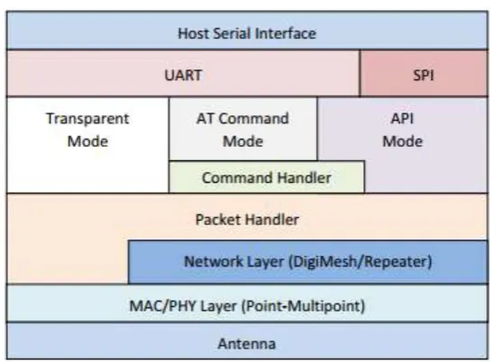
Figure 3:XBee- Pro S3B Antenna Configuration Clock Diagram
There are multiple modules in each combination. The UART module is a basic serial communication channel. (Digi International Inc., 2014). The SPI Module is standard SPI that is a four-wire logic signal bus. The transparent mode acts as a direct serial line replacement. The API mode causes the host application can interact with the networking capabilities. All the data sent and received in this operation is contained in frames that define the operations within this module. The API mode is more efficient for communication between a central control and multiple nodes.
National Instruments’ (NI) LabVIEW2013 will be utilized in this project. LabVIEW is a visual programming language for development and testing environments. Each of Kansas State’s UGV’s operating systems runs off of LabVIEW 2013, and off of a single NI myRIO-1900. The myRIO has numerous digital and analog I/O’s, serial communication ports, and has 3.3 volt, 5 volt, and 15 volt outputs.(National Instruments, 2016) The serial ports can be configured to run off of UART, SPI, or I2C protocols.
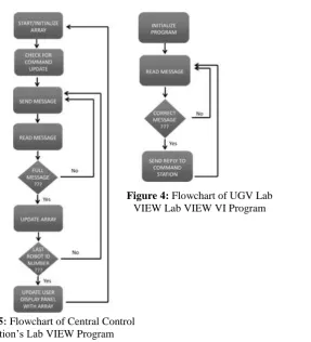
LABVIEW PROGRAMMING
command station is currently setup for two robots, but can be expanded to include additional robots if necessary by adding an additional set of inputs for another robot, and changing the input for the number of robots in the for loop. To run the program, the user must first input initial commands (event number, speed, GPS target coordinates) into the program for each of the UGVs. Second, the user runs the program, and switch the Read Robot Input Button to off. The program forms a data stringautomatically with the desired inputs in for the first robot and transmits the message. Each UGV has a unique identifier in message, so only the intended robot will read the sent message. Once the UGV has the message, it will send a message to the command station with status updates of the UGV with values indicating the battery status, current speed, location, and any sensor or equipment errors. Then, the central command station will continuously repeat this cycle with all of the robots until the user ends the program. This is thePoint to Multipoint network configuration. The program in Appendix A also allows the operator to change settings, if the UGV’s program shown in Appendix B is wired correctly. Both the central command station’s program and the UGV’s program is wired to where the UGV’s velocity can be changed.The UGV’s program is shown in Appendix B. When it receives a message with the unique identifier, it will respond with a message for the central command station. Currently, it has user inputs that form the message to be sent to the central command station. These inputs will be replaced with actual outputs from the robots once added into the rest of UGV’s actual programming.
DETERMINING THE MAXIMUM DATA TRANSMISSION SPEED
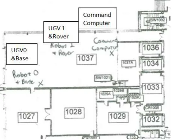
Two tests wereconducted to evaluate the performance of the program at Seaton Hall Machinery Systems Lab at Kansas State. The locations of the two UGV’s and the central control station are shown inFigure 6.Figures 7a and 7b show two of the stations used in the testing. To check the performance of the LabVIEW program, the number of bits transmitted in the message (350 bits/message)was monitored with the data string to make sure the whole string was being transferred.The first test was to test how fast the LabVIEW program could run and process the signal. Two UGVs were used to test this program with the central control station. The program was tested with a variety of LabVIEW speeds ranging from 1000ms (1Hz) to 1ms (1000Hz). It was found that the 5 ms (200 Hz) was the fastest loop time that could be ran without losing any data, with a 0.1ms delay between the UART Transmit and UART Receive functions. Messages were of 350 bits long, was being transferred in complete strings, so the first test was successful. A second test was conducted to see if interference from a device operating at a similar frequency alter the transmitted message. A Topcon GR-5 Base and rover were set up next to each of the robots from the previous tests. Since the Topcon system can operate in the 900 MHz frequency range, this could provide reasonable noise. When the command station was running at
the optimal speed, all the data was completely transmitted in the strings of 350 bits between the UGVs and the central command station.
Figure 6: Location of UGVs and Central Command Station for testing
Figure 7a) (Left) and Figure 7b) (Right): The central command station (left) and UGV 0 with base (right) during testing.
FUTURE IMPROVEMENTS
There are two items that could be done to improve the maximum message speed. First, the sent messages numbers could be declared a number type that has a smaller number of bits than a double or 26 bit unsigned integer. This would cut the message size by almost a third. Second, the actual data transmission speed could be increased when the testing is outdoors. Second, the testing facility (Seaton Hall Machinery Systems Lab at Kansas State) has been known to cause interference issues with RF transmissions. The UGVs are currently being assembled and tested, and can only be used indoors at this time. When the robots are finished and fully assembled, it is recommended that both the maximum speed and interference tests be performed again outdoors away from structures that could cause interference.
IV.
CONCLUSION
[10]. IEEE.IEEE standard for low-rate wireless networks. 1-709. doi:10.1109/IEEESTD.2016.7460875
[11]. M2 Presswire. (2016, ). Global market for agricultural drones is expected to reach $3.69 billion by 2022; finds new report. M2 Presswire Retrieved from
http://bi.galegroup.com.er.lib.k-state.edu/essentials/article/GALE%7CA449408320/4a73469a578cb9d9f4f9c1beaaca26f6?u=ksu
[12]. Mulanda, B. W. (2008). Robust communication for location-aware mobile robots using motes Retrieved from http://hdl.handle.net/2097/956
[13]. National Instruments. (2016). NI MyRIO-1900 user manual
[14]. NCRS. (2007). Precision agriculture: NRCS support for emerging technologies. (). Greensboro, North Carolina: Journal Publishing, Inc.
[15]. SparkFun. (2016a). Serial communication. Retrieved from https://learn.sparkfun.com/tutorials/serial-communication
[16]. SparkFun. (2016b). Serial peripheral interface (SPI). Retrieved from https://learn.sparkfun.com/tutorials/serial-peripheral-interface-spi
[17]. Sparkfun. (2017). I2c. Retrieved from https://learn.sparkfun.com/tutorials/i2c
[18]. Zhang, L., ZhiXin, C., & Jia, W. (November 2009). (November 2009). A networked teleoperation system for mobile robot with wireless serial communication. Paper presented at the 2009 IEEE International Conference on Intelligent Computing and Intelligent Systems, , 2 885-889. doi:10.1109/ICICISYS.2009.5358245
[19]. ZigBee Alliance. (2013). ZigBee specification FAQ. Retrieved from
https://web.archive.org/web/20130627172453/http://www.zigbee.org/Specifications/ZigBee/FAQ.aspx