e-ISSN: 2278-7461, p-ISSN: 2319-6491
Volume 6, Issue 10 [October. 2017] PP: 87-95
Study and Improvement of Submersible Motor Protection
Kamal.A.Sanad ¹, A.A.El-Samahy ², Dina Mourad ³
² Faculty of Engineering Department of Electrical Engineering ¹´ ³Faculty of Industrial Education Department of Electrical technology
ABSTRACT:
Submersible motor are subjected to hazard problems which may harm the motor winding. This paper presents a proposed simple thermal protection scheme. The proposed scheme aimed to protect submersible motor from over temperature. Over temperature is caused by many reasons such as locked-rotor, phase unbalance, over current and overload. This protection scheme is implemented practically using three temperature sensors based on microcontroller. Such temperature senses the temperature of the three phase submersible motor windings.in case of, the temperature sensor send signal to microcontroller which in turn can identify the faulty phases and hence, send the tripping signal to the proposed circuit breaker. The proposed scheme is simple and has advantages of low cost and high efficiency. Simulation and experimental results for different operating points are displayed. Results meet the expected aims.--- ---Date of Submission: 28-10-2017 ---Date of acceptance: 11-11-2017
---1.INTRODUCTION
Submersible motor pump (SMP) is a vertical induction motor [1]. The basic components of all submersible pumps are the drive, the bearing assembly, the sealing arrangement, the casing and the impeller [2]. The beginning of 1978 it is made headline news in deep-sea technology [3]. The submersible motor-pump combination is usually immersed in a fluid such as oil wells and geothermal water wells. The submersible motor unit is run on the tubing string. Both SMP and tubing string are submerged in the fluids.
The submersible motor protection technology has developed rapidly in recent years. Egypt has more than 4000 water treatment plants that depend on its work on the submersible motor. The failure of submersible motors leads to loss of the plant function [4]. So, it is necessary to develop efficient schemes for protecting submersible motor from abnormal conditions which leads to its damage.
Submersible motors are important as it has variety applications. Submersible motor is mainly used for large-scale water conservancy projects, urban water supply, drainage systems, mine drainage, emergency disaster relief and other occasions [5]. Adequate protection of induction motors is routinely achieved via locked-rotor, phase unbalance, and overload protection [2]. It is confirmed that the possible causes of insulation failures of electrical submersible motors due to corrosion of cable outside surface, mechanical damage and insulation deterioration owing to thermal stress or electrical stress [6]. This paper presents an applicable research of submersible motors protection against over temperature, which may harm the motor winding. Simulation and experimental results for different conditions are displayed. These simulation results agreed reasonably with those measured experimentally for the submersible motor 3 Kw,8.1A , 380V and P.F = 0.9 .
2.SUBMERSIBLE MOTOR FAULTS
The submersible motor is affected by a lot of faults which causes over current and so on over temperature such as reverse motor movement, increasing the level of water to be greater than the potential energy of the SMP, clogging of drag slot of the impeller by impurities and salt, close the pump SMP valve without notice and electrical fault during connection. Such faults lead to over temperature inside the engine. Sensors detect increasing of temperature. Sensors send the value of the temperature to the microcontroller. Then the microcontroller disconnects the panel.
3.PROPOSED SYSTEM
Fig.1.System Block diagram of the proposed technique
Fig.2. Schematic diagram of the proposed technique to Whole system
3.1. Rectifier
Fig.3. Implemented Rectifier Circuit
3.2. Sensor
The sensor is to measure the SMP temperature. If the sensed temperature is greater than 40°C, The sensor calls the microcontroller. The proposed scheme used 3 temperature sensors, DS18B20, installed on motor windings, input Sensor istemperatureand output is data frame (01011010-11100100)…….etc. Byte by Byte the DS18B20 is a digital thermometer provides 9 to 12-bit (configurable) temperature readings which indicate the temperature of the device. Such sensors are connected through 4.7kΩ pull up resistor to the microcontroller according to DS18B20 datasheet. The sensors features are as follows:
1. Unique 1-Wire interface requires only one port pin for communication 2. Multi drop capability simplifies distributed temperature sensing applications 3. Requires no external components
4. Can be powered from data line. Power supply range is 3.0V to 5.5V 5. Zero standby power required
6. Measures temperatures from -55°C to +125°C. Fahrenheit equivalent is -67°F to +257°F 7. 0.5°C accuracy from -10°C to +85°C
8. Thermometer resolution is programmable from 9 to 12 bits 9. Converts 12-bit temperature to digital word in 750 MS (max.) 10. User-definable, nonvolatile temperature alarm settings
11. Alarm search command identifies and addresses devices whose temperature is outside of programmed limits (temperature alarm condition)
12. Applications include thermostatic controls, industrial systems, consumer
Fig.4. shows the installed sensors and their connection with the microcontroller
3.3. Microcontroller
The microcontroller is Atmel microcontroller Mega family, atmega328. It uses 16 MHZ crystal for its oscillator so it performs the one cycle instruction during 0.0625 µsec. It is programmed using C language. So, its time response is very fast in reading. It periodically presents the readings of temperature on the LCD instantaneously.
Fig.5. Installed Microcontroller
3.4. Output Circuit
The output circuit consists of BC337 transistor and 12VDC Relay. The normally closed point is opened to stop the motor if its winding temperature increased than the set point temperature. Fig. 6 shows the output circuit configuration.
Fig.6. Output Circuit Configuration
4.EXPERIMENTAL RESULTS
The proposed protection scheme targets to protect submersible motor windings from over temperature. The under study submersible motor is 3 Kw, 8.1A, 380V and PF = 0.9, See Fig7. The threshold value of the proposed scheme is 40°C and 2 Sec.
Fig.7. the experimental setup of the proposed technique.
Microcontroller
Sensor
L C D
Buttons
Relay
Indication Relay led
Digital inputs
Digital Outputs
Digital Outputs
4.1.Reverse motor direction:
Reverse fault causes increasing in the temperature of the submersible motor. Such fault was studied by reverse the phases. The measured temperature on winding 2 was recorded 40.63 °C as shown in Fig.8, As it is seen, the red led is operating which indicate an increasing in the temperature of the submersible motor. Consequently, tripping signal is sent using the output circuit and the LCD displays "Coil2 Overheat". The following table shows the response of the scheme before and during the operation.
Fig. 8.Case of Reverse Motor Direction Fault.
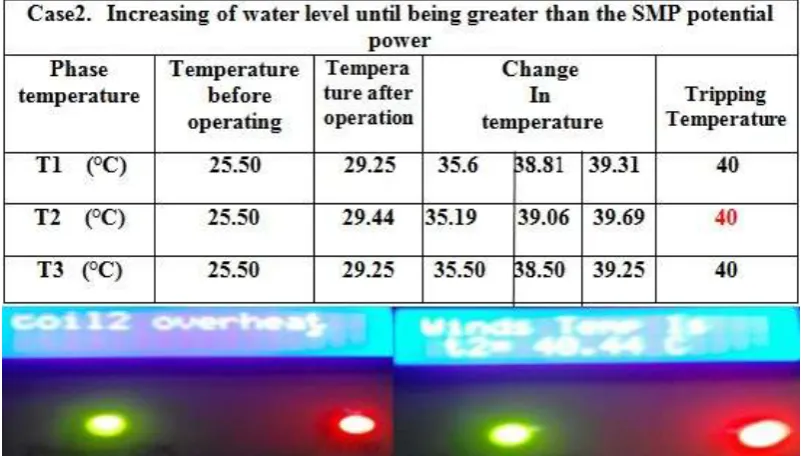
4.2. Water Level Increasing:
If the level of water is being greater than the potential energy of the SMP, the temperature of the motor will be increase. Such case was studied. The SMP is immersed at a water level deeper than its normal level inside the wells, which represents over load on the motor. The measured temperature on winding 2 was recorded 40.44 °C as shown in Fig.9, As it is seen, the red led is operating which indicate an increasing in the temperature of the submersible motor. Consequently, tripping signal is sent using the output circuit and the LCD displays "Coil2 Overheat". The following table shows the response of the scheme before and during the operation.
4.3. Clogging of drag slot of the impeller by impurities and salt :
A piece of impurities (Gravel and Grit) has been placed in the entrance to the impeller to prevent water from entering and stopping its circulation, It does to stopping the impeller. The engine is trying to spin and this led to pulling the current higher with the engine's high temperature, which represents over load on the motor. The proposed circle is set at separation temperature of 40 °C and at separation time of 2 Sec. The following table shows temperature values before and during operation on each winding. The over temperature and over current was released on winding 2 and was 40.13 °C as shown in Fig.10, As it is seen, the red led is operating which indicate an increasing in the temperature of the submersible motor. Consequently, tripping signal is sent using the output circuit and the LCD displays "Coil2 Overheat". The following table shows the response of the scheme before and during the operation.
Fig.10.Clogging of drag slot of the impeller by impurities and salt.
4.4. Close the pump SMP valve without notice:
We are always exposed to this problem at the beginning of the processing and operation of the work sites are that the valves are closed without notice, which leads to engine failure due to excessive store it. The proposal was tried in this case, The proposed circle is set at separation temperature of 40 °C and at separation time of 2 Sec. The following table shows temperature values before and during operation on each winding. The over temperature and over current was released on winding 2 and was 40.88 °C as shown in Fig.11, As it is seen, the red led is operating which indicate an increasing in the temperature of the submersible motor.
Consequently, tripping signal is sent using the output circuit and the LCD displays "Coil2 Overheat". The following table shows the response of the scheme before and during the operation..
Fig.11. Close the pump SMP valve without notice.
4.5. Electrical fault during operation:
shown in Fig.12, As it is seen, the red led is operating which indicate an increasing in the temperature of the submersible motor. Consequently, tripping signal is sent using the output circuit and the LCD displays "Coil1 Overheat andCoil3 Overheat ". The following table shows the response of the scheme before and during. the operation.
Fig.12. Electrical fault during connection.
5. SIMULATION RESULTS
Several simulation scenarios are done. PROTEUS program is used, Whole circuit of the proposed technique is simulated
.
5.1. Case1
:
Has been set
temperature of 40°C
tripping and set time 2sec tripping,
He gave an increase in
temperature in Case1, Electrical fault during operation as shown in Fig.13 and Fig.14 :
Case1:Electrical fault during operation
Phase temperature Tripping
Temperature
1. Sensor (T1) 40 ° C
2. Sensor (T2) 39 ° C
3. Sensor (T3) 40 ° C
Fig.13:Case1.
5.2. Case2 ,
Case3, Case4,
Case5:
Has been set temperature of 40 ° C tripping and set time 2sec tripping, He gave an increase in temperature Case2: Reverse motor movement, Case3: Increasing the level of water to be greater than the potential energy of the SMP in, Case4: Clogging of drag slot of the impeller by impurities and salt and Case5: Close the pump SMP valve without notice,as shown inFig.15 andFig.16:
Fig.15: Case2 , Case3, Case4, Case5
Fig.16: Case2 , Case3, Case4, Case5
6.CONCLUSIONS
Based on the proposed thermal protection scheme presented in this paper, the following conclusions can be drawn:
1. A new scheme to protect submersible motor from over temperature is developed.
2. The presented protection scheme is implemented practically using three thermometer sensors based on microcontroller.
3. The simulation results agreed reasonably with those measured experimentally for the motor used in research.
4. High-precision measure the speed of segregation and up to 0.1 degrees Celsius. 5. Showing degrees for internal engine heat is constantly on your screen
6. Overload needs a of thermal effects on its coils to separate what needs to be larger to give it to separate and passes the same class in the winding motor, which results in some cases damage the motor, but proposed time measuring and monitor the change in temperature before arriving in coils.
7. Proposed scheme costs for simple and inexpensive whileand has high efficiency giving high precision 8. Overload not protect short circuit current.
Case2: Reverse motor movement.
Case3: Increasing the level of water to be greater than the potential energy of the SMP. Case4: Clogging of drag slot of the impeller by impurities and salt.
Case5: Close the pump SMP valve without notice.
Phase temperature Tripping
Temperature
Sensor (T1) 39 ° C
Sensor (T2) 40 ° C
REFERENCES
[1] Xu Yong-ming, Meng Da-wei and Tan Jin," Research on Design Key Technologies for High-power Submersible Motor", Advanced Materials Research, Vols 383-390 (2012), pp. 414-419.
[2] V. RAMKUMAR, M.PRABHU,"STUDY OF THE EXISTING DESIGN OF IMPELLER OF 4” SUBMERSIBLE PUMP AND IMPROVING IT’S EFFICIENCY USING CFDA THROUGH THEORETICAL ANALYSIS" Journal Impact Factor (2015): 8.8293 (Calculated by GISI) , Volume 6, Issue 5, May (2015), pp. 51-55.
[3] G. Kuntz, "Advantages of Submersible Motor Pumps in Deep-Sea mining", journal of petroleum technology, Oct. 1980, Paper (SPE 6551, OTC 3367).
[4] Mohamed I. Abdelwanis, F. Selim, Ragab A. El-Sehiemy," an efficient sensorless slip dependent thermal motor protection Schemes applied to submersible pumps", International Journal of Engineering Research in Africa, Vol 14 (2015), pp. 75-86.
[5] Bao Xiao-hua, SHENG Hai-jun,"Analysis of Water Friction Loss and Calculation of Rotor 3D Temperature Field for Wet Submersible Motor", the National Natural Science Funds of China under Grant No, Applied Mechanics and Materials ,Vols 325-326 (2013), pp. 437-440
[6] Yong Fang ,Qiang Lv, Xiaowei Cheng, Xiaohua Bao," Analysis of Stress Distribution on End Winding of Large Water Filling Submersible Motor during Steady State Operation", the National Science Funds of China, (No.51177033 and No.51377039), (2012HGZY0003) and Hefei Hengda Jianghai Pump Co., Ltd. [7] Dieter-Heinz Hellmann," SUBMERSIBLE MOTOR PUMPS FOR MINE DRAINAGE
APPLICATIONS". Klein, Schanzlin &Becker AG, Frankenthaler (Pfalz) West Germany Homburg/Saar Works.
[8] M. Sundaram, P. Navaneethan, T. Dinesh Kumar," Design and Development of Energy Efficient Submersible Switched Reluctance Motor", Journal of Engineering and Technology, Jan- 2014, |Vol 4, Issue 1.
[9] ThomasW.Rauber, FranciscodeAssis,Boldt," Computational Intelligence for Automatic Diagnosis of Submersible Motor Pump Conditions in Offshore Oil Exploration",978-1-4799-2452-3/13/$31.00 ©2013 IEEE.
[10] Khaled M. Nouby, M. Ghazaly "Design a Remote Control System for Submersible Pumps Based on GSM-SMS",American Journal of Engineering and Technology Research,Vol. 16, No.2, 2016.
[11] S. Sashidhar and B. G. Fernandes," A Low-cost Semi-Modular Dual-Stack PM BLDC Motor for a PV
based Bore-well Submersible Pump",978-1-4799-4389-0/14/$31.00©2014IEEE. lun DENG, Li-jie FENG, lin-feng WANG," Innovation Design of Submersible Motor Pump Based on
TRIZ",978-1-4244-6484-5/10/$26.00 ©2010 IEEE.
[12] Shan Bai, He Wang," Sliding Mode MRAS Speed Sensor less Vector Control for SubmersibleMotor"
978-1-4673-6850-6/15 $31.00 © 2015 IEEE, DOI 10.1109/ICISCE.2015.208. [13] S. Sashidhar and B. G. Fernandes," Comparison of a Ferrite based Single, Three-phase Spoke and
Surface Permanent Magnet BLDC Motor for a PV Submersible WaterPump".978-1-4799-7800-7/15/$31.00©2015IEEE.
[14] Haicong Zhang," Research on Intelligent Power Supply Control Based on Sensor-less Temperature Identification of Electric Submersible Motor ", 2015 KIPE, 9th International Conference on Power Electronics-ECCE Asia, June 1 - 5, 2015 / 63 ConventionCenter,Seoul,Korea.
[15] S. F. Rabbi, M. A. Rahman, S. D. Butt," Modeling and Operation of an Interior Permanent Magnet Motor Drive for Electric Submersible Pumps ", 978-1-4799-4918-2/14/$31.00©2014IEEE.
[16] Yong Fang," Analysis of Electromagnetic Force Distribution on End Winding of Electrical Submersible Motor During Starting Transient Operation",IEEE TRANSACTIONS ON MAGNETICS, VOL. 49, NO. 10, OCTOBER 2013.
[17] S. F. Rabbi," Equivalent Circuit Modeling of a Hysteresis Interior Permanent Magnet Motor for Electric Submersible Pumps", DOI 10.1109/TMAG.2016.2525007, IEEE.
[18] Roshani O’Bryan, PhD," VALIDATION AND OPTIMIZATION OF HEAT TRANSFER IN THE ELECTRICAL SUBMERSIBLE PUMP MOTOR BY CFD" Proceedings of the ASME 2011 International Mechanical Engineering Congress & Exposition IMECE2011 November 11-17, 2011, Denver, Colorado, USA.