e-ISSN: 2278-7461, p-ISSN: 2319-6491
Volume 7, Issue 8 [August 2018] PP: 50-59
Design And Analysis Of Scramjet Inlet
Atulya Sethi
Amity Institute of Aerospace Engineering, Amity University, Noida,India
ABSTRACT:SCRAMJET or Supersonic Combustion Ramjet Engine is an air breathing engine, which has no rotating parts. It is similar to ramjet engine except the combustion chamber having supersonic flow and the operating Mach number is from 6 to 8. In scramjet, flow is supersonic throughout the engine. Unlike turbojet they don’t have stages of blades, so they are lighter. They have a major advantage over rockets that they don’t have to carry oxidizers onboard which further decrease their mass and increase their specific impulse. The problem statement of this paper is the design of the inlet of scramjet with the maximization of the static pressure at air inlet exit.
KEYWORDS: CFD Analysis, Inlet Modeling, Ramps , Scramjet Inlet
--- Date of Submission: 02-10-2018 Date of acceptance:13-10-2018
---I.
INTRODUCTION:The definition of ramjet is important to understand the definition of scramjet engine; scramjet is the successor of ramjet. Ramjet’s do not have any rotating parts, instead work on the principle of compression of supersonic air to low speed i.e. to subsonic speed and therefore leads to increment in static temperature and static pressure and then fuel is injected to initiate combustion, and finally flow is accelerated to supersonic speed through nozzle. Because of deceleration Mach number, the rise in temperature, density, pressure at the entrance of combustion chamber are high. Near about 6 Mach, and due to this it becomes difficult to slow down the speed to subsonic. So when the speed is not reduced to subsonic, but to desirable supersonic speed, then ramjet becomes scramjet.
Scramjet depends on vehicle speed to compress the incoming air and decelerate it before entering the burner (ramjet) ,but in scramjet engine the flow remains supersonic throughout the entire engine, whereas in ramjet the flow velocity is reduced to subsonic, so scramjet can work effectively at greater speeds.
Scramjet depends on vehicle speed to compress the incoming air and decelerate it before entering the burner (ramjet) ,but in scramjet engine the flow remains supersonic throughout the entire engine, whereas in ramjet the flow velocity is reduced to subsonic, so scramjet can work effectively at greater speeds. Theoretical and CFD analysis of 2D model operating at mach 8 with 3 ramps and 4 ramps , model operating at mach 5 with 4 ramps and model at mach 3 with ramps 4.
II.
SCRAMJET INLET:Air intake or inlet is the primary module of the aero- engine and plays a very vital role, as it is responsible for capturing the air from surrounding and transferring to the combustion chamber for combustion process without much loss, hence the engine- intake capability is necessary while considering design. As the air mass flow rate depends on the efficiency of air intake, it is necessary to design inlet with proper geometry and accurate manufacturing to achieve better engine performance.
Scramjet inlet achieves compression through introduction of ramps which produces series of oblique shock waves, causing increase in static pressure and temperature of the flow and reducing Mach number. Due to nature of design of scramjet engine, it operates at hypersonic speed and hence in this case inlets are called as diffusers. Here compression is achieved by both external and internal compression. So internal compression inlet is the longest and the heaviest and as the name suggests, the compression takes place internally. The other type of inlet is external inlet, where compression occurs externally and has no starting requirements and is the shortest. Third type of inlet is mixed compression inlet where both internal and external compression takes place, it’s longer hence heavier and also requires, more cooling for hypersonic speed.
III.
DESIGNING THE INLET: STEP 1 – Theoretical Analysis
STEP 2 – Calculation of Inlet Dimensions
Inlet length, ramp height area ratio is being calculated using formulas:
hn =An
A2(h2)
Where A is the area and,
An
A2= hndn/h2d2
d2 =dn
An
A2=
hn h2
An/A2= area ratio after each oblique shock, and h =0.152m
Now to calculate the height of ramps for the first three shocks are :
x0= h0 tan(90 − β1) Where β1 = wave angle And h0=height of engine inlet
Now, the length of fourth shock can be found out by using the formula:
x1= h0/sin δ
δ = Ramp angle
So, combining and x0 and x1we will get the total length of the inlet.
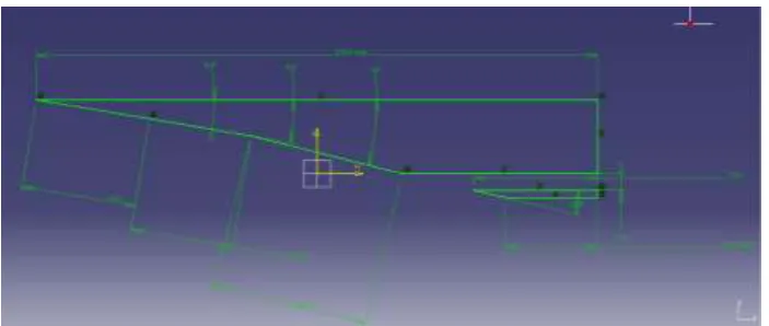
STEP 3 – Modeling in CATIA
After the calculation of all the dimensions, inlet was modeled using CATIA, and all the models are shown below. For all the models cowl angle is 0 degrees.
Step 4 – CFD Analysis
Analysis is being done on fluent 18.1(student version) and SSTK-OMEGA model has been used.
IV.
THEORETICAL VALUES FOR VARIOUS MODELS:For analysis purpose various models were being considered and values of static pressure was calculated and from those models three models based on the values of static pressure at exit was selected for CFD analysis. The results are tabled below.
S.No Number of
ramps used
Ramp Angles Mach number at
entrance of inlet
Mach number at exit of inlet
Static Pressure (pa)
1 2 9.1, 8.5 8 5.1249 16,418.05
2 3 9.5,9.6,12.6 8 5.964 91,858.81
3 3 9.5,9.6,14 8 4.698 1,19,691
4 3 5.5,11.8,15.1 8 4.354 19,228.9821
5 4 6.5,7.6,9,13.5 8 2.572 64,744.48
6 4 5.69,8.5,10.8,13.1 8 3.505 1,59,844.40
Inlet Model(For Above Three Selected Models)
Figure1: Inlet model for Mach 8 with 4 ramps (MODEL 1)
Figure 2: Inlet model for mach 5 with 4 ramps (MODEL 2)
Figure 3:Inlet at mach 8 with 3 ramps(MODEL 3)
V.
RESULTS AND ANALYSIS: Table 1: Boundary conditions for all modelsInlet Velocity inlet
Outlet Pressure outlet
Upper Boundary Wall
Lower Boundary Wall
Fore Body Wall
Fluid Air
Cowl Wall
Table 2: Inlet Boundary Conditions
Pressure 1197 pa
Mach number 8 and 5
Reference Temperature 226.5 k
Turbulent Viscosity 5
Turbulent Ratio 10
MODEL 2: AT Mach 5 with 4 ramps
Graphical Comparision Of Theoretical And Cfd Results:
Red line indicates theoretical results and blue line indicates CFD results.
Length of ramp is taken on x-axis and values of static pressure, static temperature, density and total pressure is taken on y-axis.
Model 1 –At Mach 8 with 4 Ramps
Model 2 - At Mach 8 with 3 ramps
MODEL 3: At Mach 5 with 4 ramps
VI.
CONCLUSION Model 1It has been observed that model one shows highest static pressure at the exit of the inlet. It uses 4 ramp configurations and is longest in length as compared to other 3 models, but as the pressure is highest can be used as scramjet is the future as scramjets can fulfill high mach number requirements at higher altitudes.
Model 2
For model 2 length was decreased in comparison to model 1, but then operating mach number was also reduced and hence its operation will be limited.
Model 3
Model 3 has is the second best model as on decreasing the ramp number from 3 to 4, there was reduction in total length when compared to model 1 and also not at much loss of static pressure at the exit of the air inlet.
REFERENCES:
[1]. Design and Computational Analysis of Scramjet Inlet – D. Nirmal kumar ; Hindustan Institute of Technology and Science.
[2]. Analysis and Design of a Hypersonic Scramjet Engine with starting mach number of 4.- Kristen Nicole Roberts ;The University of
Texas.
[3]. Computational Analysis of Scramjet Inlet – Nirmal kumar, Dilip A Shah. ; Hindustan Institute of Technolgy and Scince.
[4]. Fundamental of Aerodynamics – 5th edition ; John-D –Anderson.
[5]. Elements of propulsion – J.D Mattingly.
[6]. Shock tunnel studies on cowl/ ramp shock interactions in a generic scramjet inlet – D Mahapatra
[7]. Heiser and Pratt hypersonic air breathing propulsion
[8]. Aero – Engine Intake : A review and case study – Ahmed El Sayed
[9]. Application of Quadaratic Optimization to Supersonic Inlet Control.- Bruce Lehtinen ; NASA
[10]. Multidisciplinary Optimization of a supersonic Inlet Using Cartesian CFD method – David L. Rodriguez.; Desktop Aeronautics ,
inc. Palo Alto.
[11]. Scramjet Inlets by Professor Michael K. Smart, Chair of Hypersonic Propulsion, Centre for Hypersonic, The University of
Queensland
[12]. Numerical Computations For Designing A Scramjet Intake by, M. Krause, B. Reinartz, J. Ballmann,Department of Mechanics,
RWTH Aachen University.
[13]. Computational Analysis of scramjet inlet by V.Rajshree and Dinesh Kumar .
[14]. Effect on inlet performance and starting mach numbers on thye design of a scramjet engine , by P. Karhikeyan , B. Prakash ( department of aeronautical engineering , Nehru institute of technology)
[15]. Rathakrishnan ,E, Gas Dynamics
[16]. Compressible Flows – John –D Anderson