Volume 8, Issue 4 [April 2019] PP: 18-32
Studying the Effect of Different Disc Designs of Floating Caliper
Disc Brake on Braking Force
Ibrahim Ahmed1, Yasser Fatouh2, Khaled Abdelwahed2andMahmoud
Zaghloul3
1Professor, Department of Automotive Technology, Helwan University, Cairo, Egypt 2 Assistant Professor, Department of Automotive Technology, Helwan University, Cairo, Egypt
3 Researcher, Technical Education, Aswan, Egypt Corresponding Author: Ibrahim Ahmed
ABSTRACT:
Braking systems in general have been considered one of the most important parts in vehicles to improve and maintain safety requirements. Disc brakesare spreading now in most vehicles replacing drum brakes because it has a lot of advantages rather than drum brakes such as easy maintenance, light weight and higher effectiveness. It has also different shape designs which changes the contact area between the disc and the brake pad and that affect the friction coefficient and hence the resulting brake force. In this paper, experimental work was carried out using different designs of brake discs namely normal (ND), grooved (GD), drilled-grooved(DGD) of Floating Caliper Disc Brake (FCDB) and its effect on the on the braking force.A test rig has been designed and constructed that has a facility of changing various operating conditions such as brake oil pressure and rotational speed, as well as the use of brake discs with different designs.The experiments were conducted on brake oil pressure ranging from 2.5 to 10 bar and rotational speed ranging from 50 to 200 rpm, at 60 seconds of braking. The results showed that the better brake force results from normal disc (ND) but accompanied with higher friction temperature. In order to reduce the friction temperature it will be in the other discs designs. The better final friction temperature was reached in drilled-grooved (DGD) disc. By comparing the drilled-grooved disc relative to the normal disc, it was found that by increasing the brake oil pressure from 2.5 to 10 bar at constant rotational speed 150 rpm, the percentage of reduction in the mean brake force was from 15.8 %, to 9.99 % and the percentage of improvement in the final friction temperature was from 17.14% to 27.78% respectively. Also, by increasing the rotational speed from 50 to 200 rpm at constant brake oil pressure 10 bar, the percentage of reduction in the mean brake force was from 7.75 % to 12.07 % and the percentage of improvement in the final friction temperature was from 19.05% to 30% respectively.KEY WORDS: Disc,Brake, Floating,Caliper, pressure and friction.
--- ---Date of Submission: 20-12-2019 ---Date of acceptance: 31-12-2019 --- ---
1.
INTRODUCTION:
A disc brake is known generally as a kind brake that uses calipers to squeezepairs of pads against a rotor to create a friction that delay therotation of a rotating part. In addition to that it also reduce the rotational speed or to hold it stationary. The energy of motion isconverted into waste heat which must be dispersed. The disk brake is widely used in ground vehicles, especially passenger cars. However, recently the use of this type of brake has been spreading to many other kinds of ground vehicles It is either hydraulic or pneumatic are the most commonly used and offer better braking performances compared to drum brakes. Currently, disc brakes with ventilated disc rotors are now almost universally used on the front axles of cars and light commercial vehicles because of their ability to dissipate more heat than solid rotors, especially at higher speeds [1-7].Recent research has shown that ventilated disks have high heat transfer rates due to an increase in turbulence which results in a higher heat transfer coefficient of temperature. It also have a greater resistance to thermal deformation due to the uniform distribution of the materialthat reduces the thermal stress accumulated inside the rotor, which depends mainly on the geometry of the disc and the optimal configuration of the ventilation channels [8].
materials of a frictional couple. Their experiments showed that the friction coefficient decreased with increasing sliding speed and applied load, but increased with increasing disc temperature up to 300 °C and then decreasedabove this temperature. The specific wear rate was found to increase with increasing sliding speed and disc temperature [11].
The temperature distribution of rotor disc during braking operation using finite element methods has been investigated and analyzed to predict the temperature distribution on the full and ventilated brake discs and to identify the critical temperature of the rotor [12]. It provided also the heat flux distribution for the two discs.The thermal behaviour of full and ventilated discs in a transient state has been presented. This numerical simulation showed that radial ventilation played a very significant role in cooling of the disc during the braking phase. However, Severin et al. [13] have carried out an experimental study aimed at investigating the effect of the temperature on the coefficient of friction as function of the number of brakes.It was showed that the number of brakes increases the friction temperature as well as the coefficient of friction is not maintained at constant value as a result of the friction temperature increase. In addition to that the coefficient of friction hada minimum value when the temperature at a maximum value. The effect of the sliding speed on the friction coefficient of different materials was investigated experimentally [14]. It was found that the tendency of the friction coefficient to decrease as the sliding speed of the disc during braking increases. A number of different brake pads were evaluated with respect to friction behavior with changing speed the results showed that there is a negative friction –velocity behavior [15].Most pads showed a slightly higher coefficient of friction at low sliding speeds. In addition to that, it was also found that at braking with constant speed the effect slightly reduced. The effect of sliding speed and normal load on the friction and wear property of an aluminum disc sliding against stainless steel pin has been also experimentally investigated [16]. It wascarried out under normal load 10-20N, speed 500-2500r.p.m and relative humidity 70%. It showed that the friction coefficient decreased with increase of sliding speed and normal load, and the wear rates increased with the increase of the sliding speed and normal load. It was proved that the 90-hole cross-drilled pattern improved heat rejection capability of the disc between 8.8% and 20.1% depending on the vehicle speed [17].
A transient thermal, static structural and modal analysis on the disc brake rotor using three different materials and three different 36-hole ventilated profiles like has been carried out in comparison with solid disc [18]. It was noted 9%, 15% and 20% of heat reduction. A new design of 60-holes cross drilled rotor pattern and conducted a thermal analysis on it was adopted as a result of improvement till the 10th cycle were at 288.4 °C while the allowable service temperature was 550 °C [19]. So, it will be considered for the new work in this paper to make extra modification to the disc brake rotor and studying the effect of different disc designs of floating caliper disc brake on braking force.
II. EXPERIMENTAL WORK AND INSTRUMENTATIONS
In this study, a laboratorybrake test rig was designed and constructed to investigate experimentally the different parameters such as brake force, temperature and friction coefficient during braking process.The test rig has a facility of changing various operating conditions such as rotational speed and brake oil pressure, as well as the use of brake system with different designs. Some modifications were carried out to on the Floating Caliper Disc Brake (FCDB) as well as a replacement of different designs of ventilated discs namely normal, grooved and drilled-grooveddiscsto investigate the effect of different operating parameters on braking force during braking process.
Figure 1.Test rig components.
The pressurized oil generation system consists mainly of oil reservoir, a master cylinder working through screw with handle, valve and pressure gauge. This system is used to generate a constant oil pressure supplied to piston of floating caliper ventilated disc brake system to apply constant normal force that affect the brake pad as shown in figure 2.
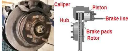
Disc brake system used in this work is afloating caliper ventilated disc brake system of a commercial vehicle of HyundaiExcel as shown in figure 3. The main components of thefloating caliper ventilated disc brake systemarefloating caliper, piston, hub, wheel bearing, rotor disc, and brake pads as shown in figure 4.
Figure 2.Schematic drawing of the test rig and measuring instrumentations.
However; the specifications of the used disc brake are shown in Table1.
Table1 specifications of the used disc brake system
2.1 Pressure measurement and normal force calculation
A pressure gauge was used during the experiments to measurethe oil pressure in the range from 2.5 bar to 10 bar.The values of the applied force are determined according to the braking oil pressure through the following equations [2-3];
Fn = P x A (1)
Where:
Fn is the normal force, N.
P is the hydraulic oil pressure, bar. A is the piston area =π
4D², mm².
D is the piston diameter, mm.
The applied normal force equivalent to the selected oil pressure is shown in figure 5 which represent the calibration chart of the applied normal force of the used brake system.
Figure 5. Brake oil pressure versus the normal force of the used brake system (calibration chart).
2.2 Speed measurement
The rotational speed of the rotor disc was measured by using a digital tachometer of (DT6234B) type with arange from 5 to 100000 rpmand accuracy of 0.5%.Four rotationalspeeds of the rotating discare selected during the test in the range from 50 to 200 rpm.
2.3 Brake Torque Calculation
A digital power meter of Schneider PM 1200 type with a range from 20 W to 300 KW and accuracy of 1% of reading for power was used to measure the power consumption by the electric motor during the braking process and no loadcondition as shown in the following equation [2];
Component Dimension
Disc outer diameter 240 mm Disc inner diameter 120 mm Disc thickness 20 mm Friction material length 110 mm Friction material width 50 mm Friction material thickness 10 mm Pad back plate length 130 mm Pad back plate thickness 6 mm Hydraulic piston diameter 50 mm
0 400 800 1200 1600 2000 2400
2.5 5 7.5 10
N
o
rm
al
Fo
rc
e
, N
Pbrake =PLoad– Pnoload (2) Where:
Pbrake is the brake power, W.
PLoad is the electric motor power during the braking process, W.
Pnoload is the electric motor power during the operation at no load case, W.
Then, thebrake torque was calculated according to the following equation [3];
Tbrake =Pbrake / ω (3)
where ∶
Tbrake is the braking Torque, Nm.
ω is the angular speed of rotating disc =2πn
60, rad/sec.
n is the rotational speed of the rotating disc, rpm.
2.4 Brake Force and Friction Coefficient Calculations
For a disc brake system there is a pair of brake pads, the brake force of the floating caliper disc brake can be calculated as follow:
Fbrake = Tbrake / 2Reff (4)
Where:
Fbrake is the brake force generated at the contact interface, N.
Reff is the effective radius of the brake pad=
ro +ri 2 , mm.
ro is the outer radius of the brake pad, mm. ri is the inner radius of the brake pad, mm.
Then the friction coefficient µcan be calculated from the relation between braking force and normal force, which can be given by:
µ = Fbrake / Fn (5)
2.5 Temperature measurement
A thermocouple of J-Type was used and fixed in the brake pad to measure the friction temperature at the contact area between the brake pad and the brake disc of floating caliper ventilateddisc brake system. The thermocouple was connected to temperature display unit as shown clearly in figure 2.
2.6Experimental works
The experimental works was carried out by using three different designs of brake discs of floating caliper ventilated disc brake on Braking Force. Three kinds of floating caliper disc brake are used as follows;
2.6.1 Normal Disc Brake (ND):
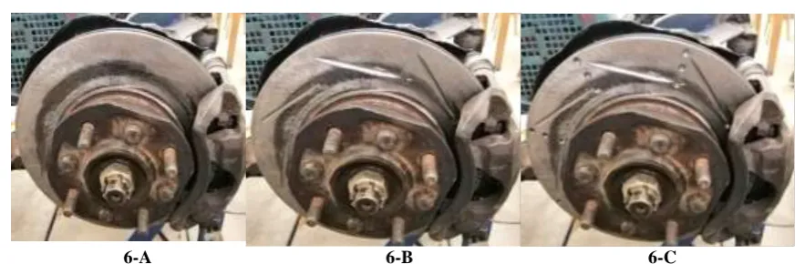
The normal discbrake faceof floating caliper ventilateddisc brake system is used in the experiment as a standard disc without any modifications and will be referred as ND as shown in the figure (6-A).
2.6.2 Grooved Disc Brake (GD):
Some modification will be made to the disc surfaces of the brake system for both sides by digging 8 grooves (slots) on each side of the disc and will be referred as grooved disc (GD). Each groove has a length of 60 mm, width of 6 mm and a depth of 3 mm as shown in the figure (6-B).
2.6.3 Drilled –GroovedDisc Brake (DGD):
An extra modification to grooved disc (GD) will be made by drilling 48 holes on both side of the disc (24 holes on each side) and will be referred as drilled-grooved disc (DGD). Each hole has a diameter of 6 mm and depth of 3 mm in addition to the 16 grooves on both sides of the disc as shown in the figure (6-C).
6-A 6-B 6-C Figure 6. Three differentdisc brake designs of floating caliper ventilated disc brake system.
III. RESULTS AND DISCUSSIONS
3.1 Effect of brake oil pressure on the brake force at rotationalspeed of 150 rpm.
The effect of brake oil pressure on the brake force of normal (ND), grooved (GD) and drilled-grooved (DGD) discsof floatingcaliper ventilated disc brake system at rotational speed of 150 rpm is presented in figures 7, 8 and 9. It can be concluded that the brake force is increased with increasing the brake oil pressure of the normal, grooved and drilled-grooved discs at 60 seconds of braking time. The fluctuation of the brake force is due to the variation of the friction coefficient with the braking time.
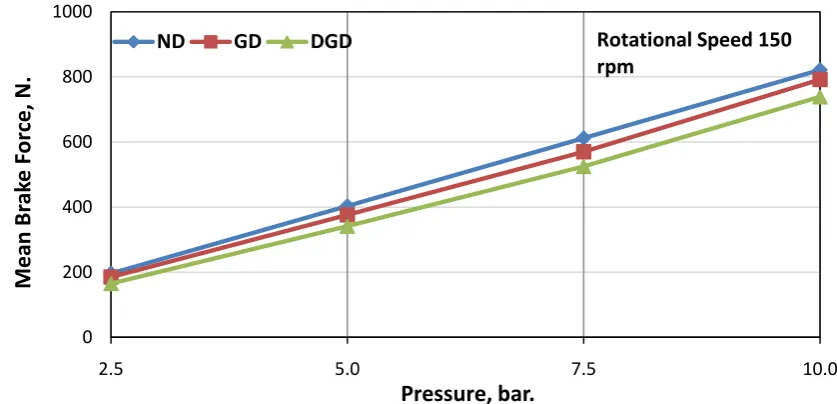
Figure 8-a shows that the mean brake force of the normal disc brake is higher than the mean brake force of the grooved and drilled-grooved discs brake at the same operation condition and this is because normal disc brake has more surface contact area with the brake pad when the brake is applied.
Figure 8-b shows comparisonbetween the mean brake forcefornormal disc (ND) brake,grooved disc brake (GD) and drilled grooved disc (DGD) brake. The results in figure 8-b also indicate that the mean brake forces for the normal disc (ND) is reached to 196,403,612 and821N at the braking oil pressure of 2.5, 5, 7.5 and 10 bar respectively. However; for the grooved disc (GD)it is reduced to 185,376, 570 and 792 N respectively at the same values of pressures and for the drilled-grooved disc (DGD) the mean brake force is reduced to 165, 341,525 and 739 N at also the same values of oil pressures.
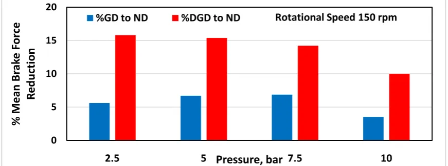
Figure 9 shows the percentage of reduction in the mean brake force of drilled grooved disc (DGD) brake and grooved disc (GD) brake relative to normal disc (ND) brake. The results in figure 9 indicate that by increasing the brake oil pressure from 2.5 to 10 bar and at constant rotational speed 150 [rpm], the percentage of reduction in the mean brake force was from 15.8 %, to 9.99 % for drilled grooved disc (DGD) brake and from 5.61 %, to 3.53 % for grooved disc (GD) brake relative to normal disc (ND) brake.
Figure 7-a 0
200 400 600 800 1000
0 10 20 30 40 50 60
Br
ak
e
F
or
ce,
N.
Time, sec.
Rotational Speed =150 rpm
P=2.5 bar
P=5 bar
P=7.5 bar
P=10 bar
Figure 7-b
Figure 7-c
Figure 7. Brake force versus time for ND, GD and DGD at different brake pressure and speed of 150rpm.
Figure 8-a.Mean brake force versus brake oil pressure for ND, GD and DGDat rotationalspeed of 150 rpm. 0
200 400 600 800 1000
0 10 20 30 40 50 60
Br
ak
e
F
or
ce,
N.
Time, sec.
Rotational Speed 150 rpm
P=2.5 bar
P=5 bar
P=7.5 bar
P=10 bar
GD
0 200 400 600 800 1000
0 10 20 30 40 50 60
Br
ak
e
F
or
ce,
N.
Time, sec.
Rotational Speed 150 rpm
P=2.5 bar
P=5 bar
P=7.5 bar
P=10 bar
DGD
0 200 400 600 800 1000
2.5 5.0 7.5 10.0
M
e
an
Br
ak
e
F
or
ce,
N.
Pressure, bar.
ND
GD
DGD
Rotational Speed 150
Figure 8-b Mean brake forcecomparison at different brake oil pressurefor ND, GD and DGD at rotational speed of 150 rpm.
Figure 9. Mean brake force reduction percentage of GD and DGD compared to ND for different brake oil pressure at rotational speed of 150 rpm.
3.2 Effect of brake oil pressure on the mean friction coefficient atrotationalspeed of 150 rpm.
Figures10and 11 show the mean friction coefficient versus the brake oil pressure at rotationalspeed of 150 rpm for the three kinds of used discs mentioned previously. The results indicated that the increase in the brake oil pressure causes an increase of the mean friction coefficient for the normal, grooved and drilled-grooved discs.The increase of the brake oil pressure from 2.5 to 10 bar causes an increase the mean friction coefficient from 0.40 to 0.42 for the normal discand from 0.38 to 0.40 for the grooved disc and from 0.34to 0.38 for the drilled-grooved disc. The results in figures 10 and 11 also indicated that, the mean friction coefficient of the normal disc is higher than the mean friction coefficient of the grooved and drilled-grooved discs at the selected brake oil pressure values 2.5, 5, 7.5 and 10 bar respectively.
0 200 400 600 800 1000
2.5 5.0 7.5 10.0
M
e
an
Br
ak
e
F
or
ce
, N.
Pressure, bar.
ND
GD
DGD
Rotational
Speed 150
rpm
0 5 10 15 20
2.5
5
7.5
10
%
M
e
an
Br
ak
e
F
or
ce
R
edu
ct
ion
Pressure, bar
Figure 10.Mean friction coefficient versus brake pressure forN, G and DG discs brake at rotationalspeed of 150 rpm.
Figure 11.Mean friction coefficient comparison atdifferent brake oil pressure for N, G and DG discs at rotationalspeed of 150 rpm.
3.3 Effect of rotationalspeed on the brake force at brake oil pressure of 10 bar.
The effect of rotationalspeed of the disc on the brake force of normal(ND), grooved (GD) and drilled-grooved (DGD)discs brake at brake oil pressure of 10 bar is presented in figures 12 and 13. It can be seen that the increase of the rotational speed of the rotating disc causes a decrease in the mean brake force of the normal, grooved and drilled-grooved discs.Figure 12-a shows that the mean brake force of the normal disc brake is higher than the mean brake force of the grooved and drilled-grooved discs brake at the same operation condition. Figure 12-b shows comparisonbetween the mean brake force for normal disc (ND) brake, grooved disc brake (GD) and drilled grooved disc (DGD) brake. The results in figure 12-b also indicate that the increase of the rotationalspeed from 50 rpm to 200 rpm causes a decrease in the mean brake force of the normal disc by 8.3% and for the grooved disc by 10.3% and for the drilled-grooved disc by 12.6%.Figure 13 shows the percentage of reduction in the mean brake force of drilled grooved disc (DGD) brake and grooved disc (GD) brake relative to normal disc (ND) brake. The results in figure 13 indicate that by increasing the rotationalspeedfrom 50 to 200 rpm and at constant brake oil pressure of 10 bar, the percentage of reduction in the mean brake force was from 7.75 %, to 12.07 for drilled grooved disc (DGD) brake and from 3.65 %, to 5.72 % for grooved disc (GD) brake relative to normal disc (ND) brake.
0.20 0.25 0.30 0.35 0.40 0.45 0.50
2.5 5.0 7.5 10.0
M
e
an
Fr
ict
ion
Co
ef
fi
ci
e
n
t
Pressure, bar.
ND
GD
DGD
Rotational Speed 150
rpm
0.20 0.25 0.30 0.35 0.40 0.45 0.50
2.5 5.0 7.5 10.0
M
e
an
Fr
ict
ion
Co
ef
fi
ci
e
n
t
Pressure, bar.
ND
GD
DGD
Rotational Speed 150
Figure 12.Mean brake forceversus rotationalspeed for N, G and DG discsbrake at brake oil pressure of 10bar.
Figure 13.Mean brake force comparison atdifferent at rotational speed forN, G and DG discsatbrakeoil pressure of 10 bar.
Figure 13. Mean brake force reduction percentage of GD and DGD compared to ND for different rotational speed at brake oil pressure10 bar.
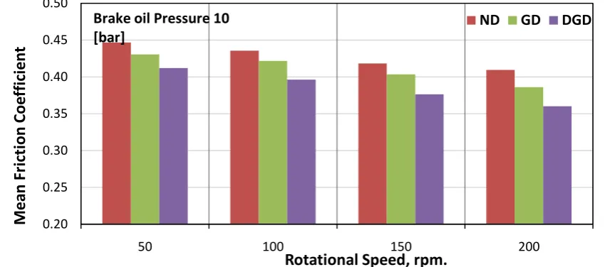
3.4 Effect of rotationalspeed on the mean friction coefficient at brake oil pressure of 10 bar.
Figures 14 and 15 show the mean friction coefficient of the normal (ND), grooved (GD) and drilled-grooved (DGD) discs versus the rotationalspeed at brake oil pressure of 10 bar. The results indicated that the increase of the rotationalspeed of the rotating disc brake causes a decrease in the mean friction coefficient for the three types of used discs. The increase of rotationalspeed from 50 to 200 rpm causes a decrease in the mean friction coefficient from 0.45 to 0.41 for the normal disc and from 0.43 to 0.39for the grooved disc and from
600 700 800 900
50 100 150 200
Me
an
Br
ak
e
For
ce,
N.
Rotational Speed, rpm.
ND
GD
DGD
Brake oil Pressure 10
[bar]
0 200 400 600 800 1000
50 100 150 200
M
e
an
Br
ak
e
F
or
ce,
N.
Rotational Speed, rpm.
ND
GD
DGD
Brake oil Pressure 10 [bar]
0 5 10 15 20
50
100
150
200
%
M
e
an
Br
ak
e
F
or
ce
R
e
d
u
ct
ion
Rotational Speed, rpm.
0.41 to 0.36for the drilled-grooved disc. It also indicated that, the mean friction coefficient of the normal disc is higher than the mean friction coefficient of the grooved and drilled-grooveddiscs at each constant speed because normal disc brake has more surface contact area with the brake pad during applying the brake.
Figure 14.Mean friction coefficient versus rotationalspeed forN, G and DG discs brake at brake oil pressure of 10 bar.
Figure 15. Mean friction coefficient comparison atdifferent rotational speed for N, G and DG discsbrake at brake oil pressure of 10 bar.
3.5 Effect of discsdesign types on the final friction temperature:
The effect of the discs design types of normal (ND), grooved (GD) and drilled-grooved (DGD) discs on the final friction temperature for rotationalspeed of the rotating disc and brake oil pressure are presented in figures 16, 17 and 18. The experiments were carried out on four brake oil pressure ranging from 2.5 to 10 bar with increment of 2.5 bar and four rotational speed ranging from 50 to 200 rpm with step of 50 rpm. The results indicated that, the final friction temperature increases with increasing of the rotationalspeed of the rotating disc and also by increasing brake oil pressure as clear obviously in figures 16, 17 and 18.
The results presented in Figure 19show the variation of temperature due to friction for the normal, grooved and drilled-grooved discs versus the brake oil pressure at rotationalspeed of 150 rpm. It shows that increasing the brake oil pressure from 2.5 barto 10 bar causes an increase in the mean value of finalfriction temperature from 35 °C to 54 °C for normal disc, from 32 °C to 46 °C for grooved disc and from 29 °C to 39 °C for the drilled-grooved disc. Figure 19 also indicates that, the final friction temperature of the normal disc is higher than the final friction temperature of the grooved and drilled-grooved discs at the selected brake oil pressure values.
0.20 0.25 0.30 0.35 0.40 0.45 0.50
50 100 150 200
M
ea
n
Fri
cti
o
n
C
o
effic
ie
n
t
Rotational Speed, rpm.
ND
GD
DGD
Brake oil Pressure 10 [bar]
0.20 0.25 0.30 0.35 0.40 0.45 0.50
50 100 150 200
M
e
an
Fr
ict
ion
Co
ef
fi
ci
e
n
t
Rotational Speed, rpm.
ND
GD
DGD
Figures 20 and 21 show the percentage of enhancement in final friction temperature during braking process of drilled grooved disc (DGD) brake and grooved disc (GD) brake relative to normal disc (ND) brake. The results in figure 20 indicate that by increasing the brake oil pressure from 2.5 to 10 bar at constant rotational speed 150 rpm, the percentage of improvement in the final friction temperature was from 17.14% to 27.78% for drilled grooved disc (DGD) brake and from 8.57% to 14.8% for grooved disc (GD) brake relative to normal disc (ND) brake. The results in figure 21 indicate that by increasing the rotational disc speed from 50 to 200 rpm at constant brake oil pressure 10 bar, the percentage of improvement in the final friction temperature from 19.05% to 30% for drilled grooved disc (DGD) brake and from 9.52% to 11.67% for grooved disc (GD) brake relative to normal disc (ND) brake. From figures 20 and 21 it was concluded that there was good enhancement in final friction temperature during braking process in the drilled-grooved disc because it has a good heat dissipation and removing ability of brake wear particles.
Figure 16.Final friction temperature versus brake oil pressure for (ND) brake with various rotational speeds.
Figure 17.Final frictiontemperature versus brake oilpressure for (GD)brake with various rotationalspeeds. 20
25 30 35 40 45 50 55 60
2.5 5.0 7.5 10.0
Fi
n
al
T
e
m
p
e
ra
tu
re
, °
C.
Pressure, bar
50 [rpm]
100 [rpm]
150 [rpm]
200 [rpm]
ND
Initial Disc Temperature 24 °C
Braking Time 60 sec.
20 25 30 35 40 45 50 55 60
2.5 5.0 7.5 10.0
Fi
n
al
T
e
m
p
e
ra
tu
re
,°
C.
Pressure, bar
50 [rpm]
100 [rpm]
150 [rpm]
200 [rpm]
GD
Figure 18.Final temperature versus brake oilpressure for (DGD) brake with various rotationalspeeds.
Figure 19-a.Final friction temperature versus brake oil pressure for N, G and DG discsbrake at rotationalspeed of 150 rpm.
Figure 19-b.Final friction temperaturecomparison atdifferent brake oil pressure forN, G and DG discs at rotationalspeed of 150 rpm.
20 25 30 35 40 45
2.5 5.0 7.5 10.0
Fi
n
al
T
e
m
p
e
ra
tu
re
. °
C.
Pressure, bar.
50 [rpm]
100 [rpm]
150 [rpm]
200 [rpm]
DGD
Initial Disc Temperature 24 °C
Braking Time 60 sec.
20 25 30 35 40 45 50 55 60
2.5 5.0 7.5 10.0
Fi
n
al
T
e
m
p
e
ra
tu
re
, °
C.
Pressure, bar.
ND
GD
Rotational Speed 150
rpm
Initial Disc Temperature 24
°C Braking Time 60 sec.
20 25 30 35 40 45 50 55 60
2.5 5.0 7.5 10.0
Fi
na
l T
em
per
atu
re
, °
C.
Pressure, bar.
ND
GD
DGD
Rotational Speed 150
Figure 20. Final friction temperature improvement percentage of GD and DGD compared to ND for different brake oil pressure at rotational speed 150 rpm.
Figure 21. Final friction temperature improvement percentage of GD and DGD compared to ND for different rotational speed at brake oil pressure10 bar.
IV. CONCLUSION:
From the results of the present study, the important conclusions are as follows:
1. The mean friction coefficient and the braking force increase with increasing brake oil pressure for normal, grooved and drilled-grooved discs of floating caliber ventilated disc brake. Also the mean friction coefficient of the normal disc is higher than the mean friction coefficient of the grooved and drilled-grooved discs and consequently the braking force of normal disc is more than grooved and drilled-grooved disc. 2. Increasing brake oil pressure from 2.5 to 10 bar at constant rotational speed 150 rpm causes a percentage
reduction in the mean brake force from 15.8 %, to 9.99 % for drilled grooved disc (DGD) brake and from 5.61 %, to 3.53 % for grooved disc (GD) brake relative to normal disc (ND) brake.
3. The increase of brake rotational disc speed at constant pressure causes a decrease of the mean friction coefficient and consequently a decrease of the mean brake force of the normal, grooved and drilled-grooved discs.
4. Increasing the rotational disc speed from 50 to 200 rpm at constant brake oil pressure 10 barcauses a percentage reduction in the mean brake force from 7.75 %, to 12.07 % for drilled grooved disc (DGD) brake and from 3.65 %, to 5.72 % for grooved disc (GD) brake relative to normal disc (ND) brake.
5. The friction temperature increases with increasing brake oil pressure and disc rotational speed. The final friction temperature of the normal disc (ND) is higher than the final friction temperature of the grooved (GD) and drilled-grooved (DGD) discs at the selected brake oil pressure values.
6. Increasing brake oil pressure from 2.5 to 10 bar at constant rotational speed 150 rpm causes a percentage improvement in the final friction temperature from 17.14% to 27.78% for drilled grooved disc (DGD) brake and from 8.57% to 14.8%for grooved disc (GD) brake relative to normal disc (ND) brake.
0 5 10 15 20 25 30 35
2.5
5
7.5
10
%
Fina
l Fri
cti
o
n
T
empe
ra
tu
re
Impro
vmen
t
Pressure, bar
%GD to ND
%DGD to ND
Rotational Speed 150 rpm
0 5 10 15 20 25 30 35
50
100
150
200
%
Fina
l Fri
cti
o
n
T
e
mpe
ra
tu
re
Impro
vmen
t
Rotational Speed, rpm.
7. Increasing the rotational disc speed from 50 to 200 rpm at constant brake oil pressure 10 bar causes a percentage improvement in the final friction temperature from 19.05% to 30% for drilled grooved disc (DGD) brake and from 9.52% to 11.67%for grooved disc (GD) brake relative to normal disc (ND) brake.
REFERENCES:
[1]. C. Owen, Automotive Brake Systems, Classroom Manual. Today’s Technician. Delmar Cengage Learning, (2010).
[2]. Ibrahim Ahmed, Khaled Abdelwahed and Mostafa M. Mekrahy, "Effect of Brake Oil Pressure on the Performance of Conventional and Modified Disc Brake at Different Initial Operating Temperatures",International Journal of engineering Inventions, Volume 7, Issue 10, pp. 1-16, (2018).
[3]. Ibrahim Ahmed, Khaled Abdelwahed, Yasser Fatouh and Mostafa M. Mekrahy, "Effect of the Sliding Speed on the Performance of Conventional and Modified Disc Brake at Different Initial Operating Temperatures",International Journal of engineering Inventions, Volume 7, Issue 10, pp. 46-62, (2018).
[4]. Nouby M. Ghazaly, Mohamed El-Sharkawy and Ibrahim Ahmed, “A Review of Automotive Brake Squeal Mechanisms”,Journal of Mechanical Design and Vibration, Vol. 1, No. 1, 5-9,(2014).
[5]. Ibrahim Ahmed, Yasset Fatouh and Wael Aly, “A Parametric FE Modeling of Brake for Non-Linear Analysis”,International Journal of Energy and Environment (IJEE), ISSN 2076-2909, Volume 5, Issue 1, pp. 97-110, (2014).
[6]. Ibrahim Ahmed and Yasser Fatouh, “Controlling the Vehicle Disc Brake Squeal Using A 10 DOF Model”,Global Advanced Research Journal of Engineering, Technology and Innovation (ISSN: 2351-5124) Vol. 1 (9), pp. 236-251, December (2012). [7]. Ahmed Abdel-Naser, Ibrahim Ahmed, Essam Allam, Sabry Allam and Shawki Abouel-seoud, “Squeal Analysis of Ventilated
Disc Brake Using Ansys”,International Journal of Energy and Environment (IJEE), ISSN 2076-2909, Volume 3, Issue 5, pp. 809-832,(2012).
[8]. Nagarajan, A., & Narayanan, M. R.,“Maximization of Efficiency for Disk Brake Material Using Composite Material by Modelling and Analysis”, International Journal of Control Theory and Applications, 9(6), 2793–2798, (2016).
[9]. Kang SS and Cho SK, “Thermal Deformation and Stress Analysis of Disk Brakes by FiniteElement Method”, J. Mech. Sci. Technol., vol. 26, no. Issue 7, p. pp 2133–2137, (2012).
[10]. C.H. Gao, X.Z. Lin, “Transient Temperature Field Analysis of a Brake in a Non‐Axisymmetric Three Dimensional Model”, J. Materials Processing Technology, Vol. 129, No. 1‐3, pp. 513‐517, (2002).
[11]. B. Öztürk, F. Arslan, S. Öztürk, “Effects of Different Kinds of Fibers on Mechanical and Tribological Properties of Brake Friction Materials”, Tribology Transactions, Vol. 56, No. 4, pp. 536‐545, (2013).
[12]. A. Belhocine, C.-D. Cho, M. Nouby, Y. B.Yi, A. R. Abu Bakar, “Thermal Analysis of both Ventilated and Full Disc Brake Rotors with Frictional Heat Generation”,Applied and Computational Mechanic, pp 5–24, (2014).
[13]. Severin, D. and, Dörsch, S., “Friction Mechanism in Industrial Brakes”, Wear 249,771-779, (2001). [14]. Blau, P. J., “Friction Science and Technology”,Marcel Dekker, Inc., (1996).
[15]. Mikael Eriksson, “Friction and Contact Phenomena of Disc Brakes Related to Squeal”, PhD thesis, Faculty of Science and Technology, Uppsala University, (2000).
[16]. M. A. Chowdhury, M. K. Khalil, D. M. Nuruzzaman, and M. L. Rahaman, “The Effect of Sliding Speed and Normal Load on Friction and Wear Property of Aluminum”,International Journal of Mechanical & Mechatronics Engineering, IJMME-IJENS, Vol: 11, No: 01, (2011).
[17]. D. B. Antanaitis and A. Rifici, “The effect of Rotor Cross Drilling on Brake Performance”, SAE, 2006-01-0691, 571-596. (2006). [18]. Gnanesh P, Naresh C and Syed Altaf Hussain,“Finite Element Analysis of Normal and Vented Disc Brake Rotor”, International
Journal of Mechanical Engineering & Robotics Research, ISSN 2278 – 0149, www.ijmerr.com, Vol. 3, No. 1, January, (2014). [19]. Mohd Firdaus Abu Bakar, Muhd Ridzuan Mansor, Mohd Zaid Akop, Mohd Afzanizam Mohd Rosli, Mohd Azli
Salim,“Thermal Analysis of Ventilated Disc Brake Rotor for UTem Formula Varsity Race Car”, Journal of Engineering and Technology, ISSN: 2180-3811, Vol. 2, June, (2011).