E-ISSN 2308-9830 (Online) / ISSN 2410-0595 (Print)
The Study of Two Dimensional Cross-Tier Interference Avoidance
in LTE-Advanced Heterogeneous Networks
Yu-Shun Liu1, Jung-Shyr Wu2 and Kang-I Lin3
1
Dept. of Computer Science and Information Engineering, Vanung University
1, 2, 3
Dept. of Communication Engineering, National Central University
12
[email protected], [email protected], [email protected]
ABSTRACT
The Third Generation Partnership Project (3GPP) has proposed enhanced Inter-Cell Interference Coordination (eICIC) for the Fourth Generation Cellular Network Standard of the Heterogeneous Networks (HetNets) in order to decrease Cross-Tier Interference. eICIC includes two schemes, Cell Range Expansion (CRE) and Almost Blank Subframe (ABS). The Fourth Cellular Network Standard LTE (Long Term Evolution) and LTE-Advanced have high transmission rate and low delay. They are important standards of current cellular networks. In areas that have bad wireless signals, signal breaking can happen very frequently. To set up some low-power small cells is a way of compensating the bad signals. How to effectively install small cells to increase overall transmission rate in HetNets becomes an important issue for LTE-Advanced standard. This paper presents two dimensional cross-tier interference avoidance scheme on the basis of eICIC. The proposed scheme allows macro cell to reserve the frequency band that has better transmission performance and pico cell to exclude the frequency band that has worse transmission rate so as to improve the User Equipment’s (UE) transmission quality and performance.
Keywords:HetNets, Cell Range Expansion, Almost Blank Subframe, Frequency Reuse.
1 INTRODUCTION
The LTE [1] downlink utilizes Orthogonal Frequency Division Multiple Access (OFDMA) modulation technique, which has high data transmission rate and is capable of effectively decrease multi-path interference and increase spectral usage rate. OFDMA modulation technique divides the whole bandwidth into multiple carriers and transfers data using multiple sub-carriers, and that is to say it divides frequency of the spectrum. The uplink utilizes Single Carrier Frequency Division Multiple Access (SC-FDMA). For terminals, SC-FDMA has lower Peak to Average Power Ratio (PAPR) and is able to increase emission efficiency and extend battery life, which subsequently saves power and decreases terminal cost of the users.
In Medium Access Control (MAC), the system resource is distribute according to different scheduling algorithms. Normally, there are two considerations. One is to optimize overall system transmission performance in order to maximize system output rate or resource usage rate; the other is about the fairness among UEs and aiming at
allowing each UE to be able to use fair resource. This paper uses Proportional Fair (PF) algorithm [2] scheduling. This algorithm uses channel more efficiently, is more conform to reality, and is fair to a certain degree. In addition, PF algorithm is also a generally-accepted algorithm within resource-distribution algorithms.
After 3GPP release 10 (R10), there has been much discussion about the problems of wireless networks of LTE in HetNets [3] - [4]. Adding some Low Power Nodes (LPN) in traditional macro cell covering areas to increase transmission efficiency in the boundaries of cells and resolve connection failure problem which users encounter in hotspots can increase macro cell coverage efficiency.
delay. Because the back-end network of relay utilizes wireless network resource, relay may cause interference to traditional cell UE and may also result in competition. Pico cell have lower emission rate, and therefore they can be regarded as traditional cell which have smaller coverage range. Pico cell is usually installed in the boundaries of macro cell or in hotspots where users concentrate. The purpose is to increase coverage rate and transmission efficiency. Compared to femto cells, both pico cell and macro cell are open to all users for connection, so they are called Open Subscriber Group (OSG). Femto cell is mainly installed in indoor environment such as homes and office buildings. However, since femto cell is installed by small group of users in the environment that fit their personal needs, femto cell cannot be open to other users. Therefore, femto cell is called Closed Subscriber Group (CSG). Operators cannot include femto cell to their operation and management similar to what they do to pico cell. Femto cell cannot communicate with neighboring cells using X2 interface either, which results in difficulty in interference coordination and many other problems in development.
Interference between cells happens usually in the boundaries of two cells. 3GPP release 8 established Inter-Cell Interference Coordination (ICIC) [5] specification to coordinate the interference between cells. In the installation environment after R10, because macro cell has many cells that have smaller power, there is cross-tier interference between heterogeneous cells besides interference between homogeneous cells. Due to the difference in transmission power, macro cell can tremendously interfere smaller cells. Therefore, eICIC is established in R10 in order to coordinate this kind of interference. With this scheme, part of the usage performance of macro cell is sacrificed to exchange for the enhancement of overall system.
Frequency Reuse [6] assures the transmission performance of the frequency band near cells and divides frequency band for the boundaries of cells, where interference is serious. Such frequency division requires more complicated coordination between cells. This technique eventually develops into Interference Coordination specification.
The purpose of CRE is to expand the service coverage of cell. It adds a CRE bias when UE measures the Reference Signal Received Power (RSRP) of the neighboring LPN, and thus UE can have better handover decision and be covered by LPN service more easily. When the RSRP of the neighboring cell is larger than the RSRP of the serving cell, and a Handover of Margin (HOM) is added and lasts for a certain period of time, the
handover will be triggered. This makes handover easier and lowers the handover threshold [7].
Because CRE is used in HetNets, UE in the service coverage of LPNs becomes more. However, when CRE is added, UE which handovers to LPN earlier will be interfered by bigger power macro cell. When CRE bias increases, it indicates that the expansion range of LPN also increases. UE that handover to LPN earlier makes the Signal to Interference & Noise Ratio (SINR) of UE of CRE become worse.
ABS in macro cell scheduling deliberately prevents a few sub-carriers from sending data. These blank sub-carriers only transmit part of the control signals and reference signals for UE to make channel estimation. Therefore, when LPN perform ABS scheduling of macro cell, the interference becomes smaller; yet the transmission performance of macro cell is sacrificed. However, CRE enables UE to handover to LPN and decreases the resource cost of macro cell. In total the overall performance is raised. The most common way of doing is allowing macro cell to ABS, and hence the UE in LPN boundaries can perform scheduling in ABS to obtain better performance.
This paper is organized as follows: 1. Introduction. 2. Related works. 3.Problem formulation. 4. Proposed algorithm. 5. Performance validation and results. 6. Conclusions. 7. References
2 RELATED WORKS
In homogeneous networks, interference between cells happens usually in the boundaries of cells. UE in the boundaries of cells may receive multiple signals from small cells simultaneously. These signals are of the same frequency. Cellular phones which are in the boundaries of small cells have high possibility to be interfered by signals from other small cells. In HetNets, small cells are added to increase overall transmission performance. Small cell which uses street or office as a unit can be operating the same frequency as big cell. Since macro cell has much bigger power than small cell, as a result, users within service of small cell face tremendous interference. Overall performance cannot be raised effectively in this way. Installing small cell become purposeless consequently.
Inter-Cell Interference Coordination. This solution mainly resolves the cross-tier interference problem in the HetNets. Besides frequency domain coordination, this solution adds time domain scheme as well. Macro cell prevents the resources blocks of a certain time interval from sending data to allow small cell to obtain better usage efficiency.
In HetNets, many LPNs have been added in the macro cell coverage range to raise performance. In order to decrease the interference between the control channels of different small cells, eICIC perform coordination for data and channels through controlling time domain, frequency domain, and power. Regarding time allocation, eICIC adds ABS while cell is performing frame allocation to prevent macro cell from transmitting data in certain period of time. This method reduces interference to small cell in this period of time significantly and achieve the purpose of raising overall transmission performance.
In many Interference immunity solutions, the authors of [7] proposed Dynamic eICIC. They established and evaluated the influence of co-channel interference to networks, modified the ABS of macro cells to maximize spectrum efficiency, improved fairness, and transmitted data in the whole HetNets in real time. However, they ignored validating the overall throughput.
Work [10] confirmed some background
information such as the location and power of small cell, calculated the power of the interference, and estimated the optimal user’s SINR, satisfaction, and throughput radius according to the calculation. The authors distributed these optimal frequency bands to macro cells and small cells, respectively, and the result showed that users obtain better fairness, and yet the throughput became worse.
Work [11] proposed Co-Channel Interference solution. The authors divided the available spectrum for macro cell and for small cell, respectively. Macro cell maintains a small cell interference table. This table is for scheduling of UE that has the possibility of being interfered and of macro cell specified spectrum. However, if UE moves slowly for too long, there will be distortion in the inspection.
The authors of [12] proposed a dynamic small cell sector boundary user coordination scheme. This is a two stage algorithm. One is in the base station and the other is in small cell. Although the result is better than the referential scheme, showing that the small cell has better through put, the complexity costs too much.
Authors in work [13] presented a scenario where small cell and macro cell communicate. Soft Frequency Reuse (SFR) program which based on
Received Signal Strength Indicator (RSSI) is applied to categorized small cells into a few groups and allocate different emission rate to RB adaptively in order to obtain better reaction of Backhaul Signalling in a small cell concentrating environment. However, the outcome throughput and spectrum usage rate are not prominent.
This paper presents a two dimensional cross-tier interference avoidance scheme on the basis of eICIC. The proposed scheme utilizes the preference level for different frequency bands among cells to reserve frequency band that has better transmission rate for macro cell and exclude frequency band where pico cell has worse transmission rate to improve the transmission quality and performance of UE as well as evaluate the overall throughput.
3 PROBLEM FORMULATION
3.1 Dynamic Optimal Almost Blank Subframe[7]
In the primal eICIC scheme, ABS determines Duty Cycle in system’s setting stage in the beginning. Because the ABS duty cycle is preset, it cannot adapt itself according to the loading and channel situation between macro and small cells. It duty cycle is set too high, the whole system will bias to users of LPN; if LPN has low loading, the macro cell spectrum will be extremely wasted. Besides, this paper use pico cell as LPN. Therefore, the LPN mentioned in this paper will be called pico cell.
The parameters for evaluating the overall system performance are Sum Rate and Product Rate. Sum rate is for evaluating throughput and product rate is for fairness [9]. Here we define the two performance parameters is as follows.
( ) ∑ ··· (1)
( ) ∏ ··· (2)
denotes the Data Rate of the UE ith under the service of cell s. Equation (1) is the parameter of sum rate. Equation (2) is the parameter of product rate. They represent the rules in the process of optimization.
is then categorized for macro cell user and for pico cell user. Pico cell users are again categorized into In-Cell (INC) users and cell boundary (cell range expansion) users. With ABS duty cycle parameter θ, Equation (1) and Equation (2) can be written as follows.
∏ (
) ∏ ∏ (
)
( ) ∏ ∏ [(
) ]
( ) ∏ ∏ ∏ ( ) ∏ ∏ ··· (4)
, , represent the transmission performance of the macro cell user, pico cell range expansion user, and pico cell In-Cell user, respectively. , ∑ , ∑ represent the sum rate parameter of macro cell user, pico cell range expansion user, and pico cell In-Cell user, respectively.
, ∏ , ∏ correspond to the product rate utility parameter of macro cell user, pico cell range expansion user, and In-Cell user.
The value of θ is based on the enhanced Inter-Cell Interference Coordination scheme mentioned previously: for macro cell, θ is duty cycle, and therefor performance parameter should multiply (1-θ); for pico cell, cell range expansion user uses θ for data transmission, and therefore performance parameter multiplies θ; finally, because θ is used by pico cell range expansion user, therefore In-Cell user should use (1-θ) and performance parameter should multiply (1-θ).
When sum rate is at maximum, the duty cycle is more easily to be determined:
(∑ ∑
( ) (∑
∑ ∑
( ) )) ··· (5)
Where, ( ) is Unit Step Function. is assigned 0.6 (60%) according to specification.
This solution means that θ is set to the maximum when cell range expansion utility exceeds both of macro cell and In-Cell utility. On the contrary, θ is set to the minimum, that is 0, when cell range expansion utility isn’t better than macro cell and In-Cell utility. This implies that if we use sum rate parameter, the value of duty cycle will jump between 0 and 0.6. The best solution of the θ of product rate can be calculated by differentiation.
∑
∑ ∑ ··· (6)
According to the principle of fairness, the duty cycle derived from the optimization of product rate is the ratio of the number of cell range expansion users to the total number of users of the whole system.
No matter the optimal ABS duty cycle is based on the overall throughput or on fairness, the value of the duty cycle is varied with the the transmission quality and the loading of different areas. On the basis of the concept, this paper adds frequency reuse to further improve the performance of the system.
3.2 Frequency allocation
The main idea of Time Domain eICIC scheme is to sacrificed the performance of macro cell to exchange significant performance raise of the pico cell boundary user. If the number of pico cell users is enough, corresponding macro cell resource can be exchanged.
Our opinion in this paper is, on the condition that cells can communicate with each other using X2 interface, the resource provided by macro cell to exchange for overall performance increase bases not simply on time domain, but rather on the preference for frequency band. The reason is, for cells, it is difficult to estimate in which time interval they can obtain good transmission performance or bad transmission performance, but it is much easier for cells to distinguish in which frequency bands they can obtain better transmission performance. Therefore, they should reserve these frequency bands while other frequency bands which provide worse performance can be given to other cells. This is also the main idea of frequency reuse.
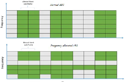
In HetNets, because pico cells are usually covered by macro cell, and because of the cell range expansion scheme, UEs are almost all distributed in pico cells. On the condition that pico cells can use the complete resource, we made a few changes to the original ABS scheme, as shown in Figure 1 and Figure 2.
Fig. 1. Original time domain enhance Inter-Cell Interference Coordination
Figure 1 shows the original time domain eICIC. Figure 2 is the idea proposed in this paper. The green frequency band is where macro cell can obtain higher transmission performance. Therefore, we reserved it and marked it in green. We moved the resource blocks which supposed to transmit ABS to other less efficient frequency bands. In this way, the performance of macro cell can be increased, and small cell can obtain better efficiency in those bands.
The green blocks in Figure 3 indicate the part where pico cell can obtain better transmission quality because macro cell has transmitted ABS. If we observe the difference between the two pictures from pico cell’s viewpoint, the green blocks which have better quality are moved to other parts. However, according to scheduling scheme, resource blocks that have better quality can still be given to users who have higher demand. For pico cell, the advantage of eICIC is not sacrificed.
Fig. 3. Illustration of pico cell resource
3.3 Two dimensional cross-tier interference coordination avoidance scheme
According to dynamic optimized ABS equation, the sum rate and the product rate are:
Sum rate:
∑ ∑
∑ ∑ ∑
∑ ∑ ∑
··· (7)
Product rate:
∏ ∏ ∏ ∏ ∏
∏ ∏ ∏
(8)
In the above equations, θ is replaced by parameter , , and respectively. These parameters will be introduced later. Here, and
represent RB data rate instead of user data rate;
i is resource block index, and since resource frequency band is 20MHz, the value of i is 1~100; j is pico cell index; k is time index which uses 1ms as one unit and 10ms as one cycle. Channel rate is defined by Shannon Theorem:
( ) ··· (9)
SINR is categorized into macro cell and pico cell. Pico cell category is categorized into that is interfered by macro cell and that is not interfered by macro cell. They are expressed as follows.
··· (10)
··· (11)
··· (12)
Equation (10) and (11) represent the SINR of pico cell [15]. Equation (10) represents the SINR of pico cell interfered by macro cell, and equation (11) represents the SINR of pico cells not interfered by macro cell; Equation (12) represents the SINR of macro cell. There is only one macro cell in the simulation environment of this paper. Therefore, the macro cell won’t be interfered by other macro cells.
4 PROPOSED ALGORITHM
Figure 4 is index matrix x. 1 is marked in green and represents that macro cell transmits data in this resource block. 0 is empty with no data being transmitted. X is an index matrix of 100x10. If a cell decides to transmit data in this resource block, then the corresponding value should be 1, or otherwise 0. For example:
= [1,1,0,1,0,0,0,1,1,1]
= [1,1,0,1,0,0,0,1,1,1]
= [0,0,1,0,1,1,1,0,0,0]
represents the data is transmitted in In-Cell,
and so does ; is the transmission in pico cell range expansion; ( ) represents pico cell range expansion user transmits data when macro cell is not transmitting data.
x is planned with the following steps:
1. Deciding the ratio of ABS: ABS is chosen in the ascending order from 0~6 in 10ms cycle. The ratio is denoted as parameter .
2. Deciding the ratio of reserved frequency: in this paper, we decide that macro cell have the priority to reserve the frequency band it prefers. The value of is assigned from 1~100. However, considering the problem of complement later, we set a condition as:
( ) ( ) ··· (13)
The extra part which macro cell reserves should be smaller than the reserved frequency and should not be an original ABS block. In this way, there is enough resource blocks to complement the amount of original ABS blocks.
3. Complementing the empty part which are short of because of macro cell’s reservation: according to the information sent back from UE, we can judge which frequency band that each cell has the best efficiency in the previous time interval and make a preference rank. Because our consideration is about the heterogeneous interference between macro and small cells, it is easy to make decision of the preference frequency band of macro cell since there is only one. But, there can be a few to dozens of pico cells, and thus the preference rank of pico cell should be designed in another way in order to find the rank that will be beneficial to the overall system.
There are two considerations in making the preference rank of pico cell:
1. The distance to macro cell (d). The small cell which is closer to macro cell has the strongest interference, and thus the weight in decision making should be higher.
2. The number of victim users in cell range expansion areas of small cell. The more victim users there are, the higher the weight is. The preference rank is generated by vote by pico cells. However, if each pico cell has one vote, it is easy to generate same votes. Therefore, we add a weight parameter here: let the number of victim users be v and the distance to macro cell be d.
(
) ··· (14)
is the coverage distance of macro cell, and is the maximum number of victim users, that
is, the total number of users in pico cell.
The designed parameter can be figured out by Equation (9). When v increases, M decreases; similarly, when d decreases, M increases. The influence of v and d to weight is set to 50%, respectively. If we want to decide the weight using distance or the number of victim users, we can make changes here; the outcome of M will be a value between 0 to 1.
When M has been calculated, we change the value of each vote from one vote to 1+0.1 vote to allow weight to decide the order of frequency bands but won’t exceed the original value of one vote.
When the strategy of pico cells has been decided, we can obtain the frequency bands which have higher votes, indicating that pico cells have worse transmission quality in these bands. We complement the blank part which macro cell had planned in the order shown in Figure 5.
Now, we have temporarily established the bit map of x. We then figure out the corresponding performance using Equation (7) and (8). By trying all combinations of and , we obtain their
best performance and the corresponding matrix x. The best allocation is obtained accordingly. The flowchart of generating index matrix x is shown in Figure 6.
Figure 6 Flowchart of generating index matrix x
5 PERFORMANCE VALIDATION AND
RESULTS
5.1 Simulation environment
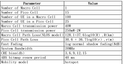
In this paper, we use Matlab as the simulation software. We define the simulation environment parameters according to 3GPP regulation, as show in Table 1.
In the installation environment, a macro cell contains 15 pico cells; the emission power of macro cell is set at 40W; the coverage range is 2km; the number of UEs in its service is 100. The emission power of pico cell is set between 250mW to 2W; the coverage range is between 80m to 120m; the number of UEs in its service is 25. The system bandwidth is 20MHz; 1ms is allocated with 100 resource blocks, not including carrier aggregation. Each simulation lasts for 30 seconds. x matrix is updated every 40ms basing on the ABS pattern of the specification. The distribution of cells and UEs is as shown in Figure 7.
Table 1: Simulation environment parameters
Figure 7 Distribution of cells and UEs
5.2 Discussion of simulation results
Table 2 compares the average throughput per UE in three kinds of environment under different interference coordination schemes. They are environment with no eICIC, with original eICIC, and with the proposed two dimensional cross-tier coordination avoidance scheme. In the environment with no eICIC, pico cell is interfered seriously. The average throughput is 9.97Mbps. When original eICIC is used, the performance increases
significantly from 9.97Mbps to 15.55Mps
(+55.97%). In the environment with the proposed two dimensional cross-tier interference avoidance scheme, pico cell has less interference. The average throughput per UE is 15.81 Mbps. Compared to no eICIC, the performance has increased to 115.81Mps (+ 58.58%).
Parameter Value
Number of Macro Cell 1
Number of Pico Cell 15
Number of UE in a Macro Cell 100
Number of UE in a Pico Cell 25
Marco Cell transmission power 40W
Pico Cell transmission power 250mW~2W
Macro Cell Path Loss(NLOS model) 128.1+37.6log10(R) ,R(km)
Pico Cell Path Loss 30.6 + 36.7log10(r) ,r(m)
Fast Fading log-normal shadow fading(8dB)
System Bandwidth 20MHz
CRE bias(db) 3,6,9,12,15
ABS bitmap renew period 40 ms
Table 2: Average throughput per UE in three kinds of environment
5.2.1 The optimization outcome of sum rate utility parameter
Figure 8 shows the average UE throughput (sum rate utility) corresponding to different CRE bias. The throughput increases when bias is in the range of 3db, 6db, and 9db. More UEs handover earlier to pico cells, and users under eICIC scheme obtain better frequency bands. Therefore, the throughput increases. When CRE bias is in the range of 9db, 12db, and 15db, the throughput decreases. The reason is when bias raises to a certain degree, UE will handover to pico cells too early and the SINR is bad. Thus, the throughput is not as good as at 9db, and a descending trend appears.
Fig. 8. Average UE throughput (sum rate utility)
Regarding the average throughput performance, the UE handover earlier to pico cell when bias increases, and thus the service range of pico cell enlarges. As a result, the interference between pico cells also increases. Comparing the method proposed in this paper to original eICIC, the proposed method has better performance, as shown in Figure 9.
Fig. 9. Improvement percentage (sum rate) of the proposed scheme compared to original eICIC
We categorize UE into Macro, Pico-CRE, and Pico-INC for discussing their improvement degree, respectively. Under eICIC, macro cell sacrifices the resource to allow pico cell to transmit data for the increase of overall system performance. In this paper, macro cell is in the two dimensional
interference coordination avoidance scheme, and thus it reserves part of the resource for itself. When sum rate is used as the performance parameter, the macro cell is seen to have significant improvement, as shown in Figure 10.
Fig. 10. Macro UE improvement percentage (sum rate)
Regarding pico cell, the frequency bands used by UE of Pico-CRE are the preference bands decided by pico cells, and therefore the throughput has raised a little. Finally, regarding Pico-INC, because some of the frequency bands have been reserved for UE of Macro cell and Pico-CRE, UE of Pico-INC can use only the rest of the bands. But, UE of Pico-INC are closer to the cells, so the throughput is still acceptable, as shown in Figure 11.
Fig. 11. The improvement percentage of Pico UE (sum rate utility)
5.2.2 The outcome of the optimization of product rate utility parameter
Similar to sum rate, the boundary point of the throughput trend of product rate also locates at 9db. When bias is less than 9db, the throughput is an increasing trend. When bias is larger than 9db, the throughput trend is descending due to the increase of interference. Product rate emphasizes fairness, the performance is lower than sum rate as a result, as shown in Figure 12.
Fig. 12. Average UE throughput (product rate utility)
No eICIC (bias=0db)
Original eICIC (bias=12db)
Proposed scheme (bias=12db) Average
With respect to the improvement degree, the overall performance is improved. The difference from the case of sum rate is that the improvement of product rate does not have a regular ascending or descending trend in accordance to the CRE bias, as shown in Figure 13.
The improvement of macro cell user throughput is still relatively obvious. Considering the principle of fairness, macro cell cannot reserve the frequency bands it needs just as what it does in sum rate case. Therefore, the improvement is not as significant as that of sum rate case, as shown in Figure 14.
Fig. 13. Improvement percentage (product rate utility) of the proposed scheme compared to the original eICIC
Fig. 14. Macro UE improvement percentage (product rate utility)
Regarding pico cell, the improvement of Pico-INC user throughput grow slightly. Improvement of Pico-CRE user throughput is random. The overall performance increases, as shown in Figure 15.
Fig. 15. Pico UE improvement percentage (product rate utility)
Product rate is the optimization basing on the principle of fairness. A performance judging value, Jain Index [9], is introduced here in addition to throughput.
( ) (∑ )
(∑ ) ··· (15) There are N UE in the system.
represent the data rate from UE1 to UEN , respectively.
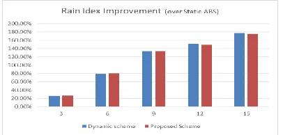
Both the fairness of dynamic eICIC and that of
the proposed two dimensional cross-tier
interference coordination scheme improve
significantly in Jain index case. But, because both update duty cycle dynamically, they don’t have much difference between each other, as shown in Figure 16.
Fig. 16. Jain index improvement percentage
6 CONCLUSIONS
The goal of this paper attempts to allow macro cell which looses a great deal of resource due to ABS scheme to properly allocate frequency bands in order to fulfill the original motivation of ABS and increase overall performance, especially the transmission performance of macro cell itself.
HetNets will still be an important issue in the future. When machine-type users join in the networks, the total number of UEs will become enormous. Homogeneous interference between small power cells and relays will become more and more serious. How to manage resource more efficiently and avoid interference as data transmission demand is increasing, besides time and frequency band coordination, using power control interference coordination scheme in the coverage range is one of the subject matters. Using these coordination factors sufficiently in the new environment to obtain better resource quality and performance is a goal for researchers to put effort into.
7 REFERENCES
[1] Stefania Sesia, Issam Toufik, and Matthew Baker, “LTE the UMTS Long Term Evolution from theory to practice”, July.2011
and Communication Technology Convergence (ICTC), 2010 International Conference
[3] Aleksandar Damnjanovic, Juan Montojo, Yongbin Wei, Tingfang Ji, Tao Luo, Madhavan Vajapeyam, Taesang Yoo, Osok Song, And Durga Malladi, “A Survey On 3gpp Heterogeneous Networks” 2011 June IEEE Wireless Communications.
[4] LTE Advanced: Heterogeneous Networks, http://www.3glteinfo.com/lte-advanced-heterogeneous-networks/
[5] Ronald Y. Chang, Zhifeng Tao, Jinyun Zhang, and C.-C. Jay Kuo, “Multicell OFDMA Downlink Resource Allocation Using a Graphic Framework” IEEE Transactions On Vehicular Technology, Vol. 58, No. 7, September 2009
[6] Marko Porjazoski and Borislav Popovski,
“Analysis of Intercell Interference
Coordination by Fractional Frequency Reuse in LTE”
[7] Subramanian Vasudevan, Rahul N. Pupala, and Kathiravetpillai Sivanesan, “Dynamic eICIC – A Proactive Strategy for Improving Spectral Efficiencies of eterogeneous LTE Cellular Networks by Leveraging User Mobility and Traffic Dynamics” IEEE Transactions On Wireless Communications, Vol. 12, No. 10, October 2013
[8] Heterogeneous Networks in LTE – 3GPP, http://www.3gpp.org/technologies/keywords-acronyms/1576-hetnet
[9] R. Jain, D.-M. Chiu, and W. Hawe, “A quantitative measure of fairness and discrimination for resource allocation in shared computer systems,” DEC Research Report TR-301.
[10]Christos Bouras, Georgios Kavourgias,
Vasileios Kokkinos, Andreas
Papazois,“Interference Management in LTE
Femtocell System Using an Adaptive
Frequency Reuse Scheme”, Computer
Technology Institute and Press Diophantus and
Computer Engineering and Informatics
Department, University of Patras, Greece, WTS, pp. 1-7, 2012
[11]Yi Wu, Dongmei Zhang, Hai Jiang, Ye Wo, “A Novel Spectrum Arrangement Scheme for Femtocell Deployment in LTE Macrocells”, 2009 IEEE 20th International Symposium on
Personal, Indoor and Mobile Radio
Communications, pp. 6-11, Sept 2009
[12]Mahmudur Rahman, Halim Yanikomeroglu, “Enhancing Cell Edge Performance: A Downlink Dynamic Interference Avoidance Scheme with Intercell Coordination”, IEEE
Transaction on Wireless Communication, Vol 9, No. 4 April 2010
[13]Chen Jiming, Wang Peng, Zhang Jie, “ Adaptive Soft Frequency Reuse Scheme for In-building Dense Femtocell Networks”, IEEE Journals & Magazines China Communications, Vol 10, Issue. 1, Jan 2013
[14]David L´opez-P´erez, Holger Claussen, “Improved Frequency Reuse through Sector Offset Configuration in LTE Heterogeneous Networks” IEEE ICC 2014 - Mobile and Wireless Networking Symposium
[15]Supratim Deb, Pantelis Monogioudis, Jerzy Miernik, and James P. Seymour, “Algorithms
for Enhanced Inter-Cell Interference