Varun Krishnan K S
Department of Electronics and Electronics Engineering Toc H Institute of Science and Technology, Arakkunnam, Kerala, India
Dr.Preethi Thekkath
Department of Electronics and Electronics Engineering Toc H Institute of Science and Technology, Arakkunnam, Kerala, India
Abstract- Electric drives are gaining much importance in the present scenario, as the conventional energy sources are at the verge of depletion. The PMDC (Permanent Magnet Direct Current) Motor Drives are becoming popular, for its usage in compact electric vehicles. This paper presents a comparative study of well-known KY converter, its coupled inductor step-up derivative, with the boost converter to accomplish a performance evaluation of the same. In this comparative study, effectiveness of converter unit in the drive, power quality concerns of the produced DC output and its operation reliability are taken into account. Some simulation results are provided to emphasis the comparison between above mentioned converter topologies.
Keywords – Comparative Study, PMDC Drive, KY Converter, Step Up Converters
I. INTRODUCTION
PMDC motors are known for its compact size, due to the absence of field windings and circuitry to provide the magnetic field. High efficiency, high starting torque and a linear speed/torque curve are its advantages when compared to the conventional wound rotor type DC motor. Since PMDC drives are widely used in compact electrical vehicles, converters need to provide a high step-up ratio, as high voltage DC battery cannot be housed in the compact structure.
Different PMDC topologies, their characteristics and modes of operation are discussed in [1-3]. Topology discussed in [1] require a large number of components and also require an inverter - converter dual stage operation, which will increase the complexity. In [2], converter topology requires much greater filter inductance value to sustain the CCM operation. KY converter have an inherent quality of maintaining Continuous Current Conduction (CCM) throughout the operation. Topology is quiet simple with less number of components.
The rest of the paper is organized as follows. A detailed comparative study between step-up KY converter and boost converter is explained in section II. Simulation results are presented in section III. Concluding remarks are given in section IV.
II. COMPARATIVE STUDY
A. Boost Converter –
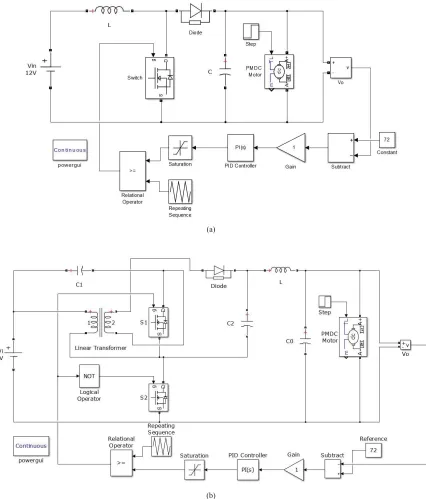
Boost converter is the basic step up converter topology with two semiconductor devices and one energy storing element. The key principle that drives the boost converter is the tendency of aninductorto resist changes in current by creating and destroying a magnetic field. During this course some amount of energy is stored in the inductor winding, which is fed to the output. Circuit diagram of boost converter topology is shown in Figure 1
Mode of operation of boost converter can be explained in two stage, when switch S is closed and when switch S is opened.
Figure 1. Circuit diagram of Boost Converter
(b) When the switch S is opened, current will be reduced as the impedance is higher. The magnetic field previously created will be destroyed to maintain the current towards the load. Thus the polarity will be reversed (means left side of inductor will be negative now). As a result, two sources will be in series causing a higher voltage to charge the capacitor through the diode D.
If the switch is cycled fast enough, the inductor will not discharge fully in between charging stages, and the load will always see a voltage greater than that of the input source alone when the switch is opened.
B. Inductor Coupled Step-Up KY Converter –
Figure 2. Circuit diagram of Inductor Coupled KY Converter
This topology combines KY converter with a traditional synchronously rectified (SR) buck-boost converter and a coupled inductor with the turns ratio, which is used to improve the voltage gain. The duty cycle and the turns ratio are independent, which means that tuning the duty cycle does not affect the turns ratio and vice versa. And voltage gain can be determined by adjusting both the duty cycle and the turns ratio [4]. Most of the converter topologies has one Right-Hand Zero (RHZ) in the transfer function under the continuous current mode (CCM) owing to instable operation. This will cause the parameters of the corresponding controller to be difficult to design and the transient load response to be slow[5].
C. Comparison between KY and Boost –
Boost Converter KT Converter
Duty Ratio
For a high step up ratio, large duty ratio is required, owing to a higher conduction loss.
Voltage gain is attained with the combine action of duty ratio and turns ratio. A smaller duty ratio is sufficient even for high step up ratio
Output Current Pulsation
Does not have an output inductor generating a pulsating output current. This will result in a high voltage ripple
Topology contain an output inductor which make output current non pulsating
Stability RHZ during the CCM operation reduce the stability Have a high level of stability even with CCM operation
Table 1. comparison of Boost Converter and Inductor Coupled KY converter
III. SIMULATION AND RESULT
Simulation in done in Matlab 2014a with same design conditions and the obtained simulation results are given below.
A. Design Parameters
Components of boost converter and KY converter topology is done with the following system requirement
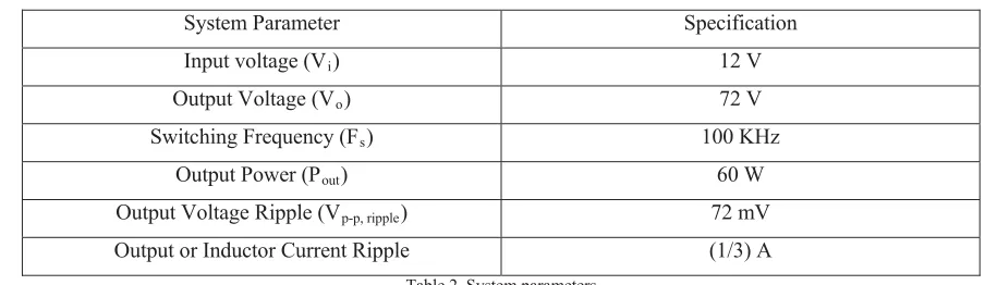
System Parameter Specification
Input voltage (Vi) 12 V
Output Voltage (Vo) 72 V
Switching Frequency (Fs) 100 KHz
Output Power (Pout) 60 W
Output Voltage Ripple (Vp-p, ripple) 72 mV
Output or Inductor Current Ripple (1/3) A
Table 2. System parameters
Design equation of boost converter is given in [6]. And KY converter is designed with the design equations provided in [4].
Components of Boost Converter Specification
Output Capacitor (C) 96.37 μF
Inductor (L) 302.91 μH
Duty Ratio (D) 83.33%
Table 3. Design Values of Components in Boost converter
Components of KY Converter Specification Magnetizing Inductor (Lm) 148.7 μH
Output Inductor (Lo) 180 μH
Energy Transferring Capacitor (C1) 174 μF
Charge Pumping Capacitor (C2) 69.4 μF
Output Capacitor (C0) 300 μF
Duty Ratio (D) 50%
Table 4. Design Values of Components in KY converter
(a)
(b)
(a) (b)
Figure 4. Output Voltage Waveform of (a) Boost Converter (b) Inductor Coupled KY Converter
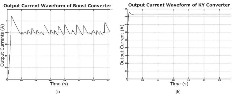
Voltage waveform of boost converter is having a high amount of ripple so that it swings around the final desired value of 72 Volts. Voltage ripple is due to the pulsation in output current shown in Figure 5(a). Whereas in the case of KY converter output voltage settle down to the desired voltage level in a quick succession.
D. Waveform of Output Current
(a) (b)
Figure 5. Output Current Waveform of (a) Boost Converter (b) Inductor Coupled KY Converter
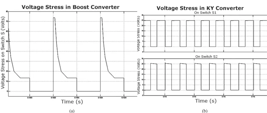
E. VoltageStress
(a) (b)
Figure 5. Voltage Stress in (a) Boost Converter (b) Inductor Coupled KY Converter
Voltage stress in Boost Converter on switch S is somewhat equal to output voltage level 72 V. As the output voltage level increase, voltage stress on the switches will also increase, making the converter switches expensive. On the other hand, voltage stress on the switches of KY converter is independent of output voltage and it is equal to twice of input voltage, which is 25 V in this case.
IV.CONCLUSION
Through this comparative study, performance of Inductor coupled KY converter is evaluated. Its superiority over boost converter in output voltage regulation and stable operation in the CCM operation range is evaluated using simulation results. KY converter is well suited to be a step up converter, with high voltage ratio, and can be used in the PMDC motor drives for compact electric vehicles.
REFERENCES
[1] M. Ammal Dhanalakshmi, G. Arthiraja, B. Arunkumaran, Ashly Mary Tom, “An Improved DC/DC Converter with Reduced Voltage Stress and Filter Circuit for PMDC Motor Drives”, ICCPCT- IEEE, pp. 736-741, 2004.
[2] Mahendra Chandra Joshi, Susovon Samanta,"Modeling and Control of Bidirectional DC-DC Converter Fed PMDC Motor for Electric Vehicles", Annual IEEE India Conference (INDICON),2013.
[3] Mohamed Y. Tarnini,"Microcontroller Based PMDC Motor Control for Driving 0.5KW Scooter", 16th International Power Electronics and Motion Control Conference and Exposition,pp. 1024-1028, Sept.2014.
[4] Hwu K.I., Yau Y.T., "A novel voltage-bucking/boosting converter: KY buck-boost converter", International Conference on Industrial Technology, IEEE, pp.1-4, Apr. 2008.