e-ISSN: 2278-067X, p-ISSN: 2278-800X, www.ijerd.com
Volume 12, Issue 6 (June 2016), PP.12-17
A Review on Model Based Design Flow for Implementation of
PRBS Using Matlab and correlate with Correlation Radar Using
VHDL
1
Shrikant Kumar,
2Paresh Rawat
1Student, Department of ECE, Truba College of Science and Technology Bhopal India 2Head of Department of ECE, Truba College of Science and Technology Bhopal India
Abstract:
Radars square measure general devices for defense, survey & vehicle steerage systems but the delicate style & needs of pricey devices makes it out of reach to the daily applications. we tend to projected associate degree approach to creating the device easier, cheaper & to form the device abundant compatible for vehicles so it will be used for machine-controlled vehicle driving system also as collision shunning system though several alternative options will be additional thereto like vehicle signature reading will be accustomed determine the kind of car like deliverance or emergency vehicles.Keywords:-
Anti-collision, Correlation Radar, PRBS, Radiolocation, Target Detection, M-SequenceI.
INTRODUCTION
The measuring device is that the basic demand of anti-collision system therefore several form of measuring device has been already projected consistent with its property and demand of system .Anti-collision system use measuring device detection to live distance to obstacles and obstacles relative speed. Several radar microwaves, radar microwave measuring device, radio detection and ranging, radiolocation, measuring instrument, measuring system, measuring device antennas were developed however correlation radar is that the most up-to-date radar employed in Anti-collision system. It’s a nasty and incorrect estimation of the protection distance from the motive force that cause automobile accidents on the road. The protection distance is that the minimum distance needed to prevent a braking vehicle.
The distance estimation is worsened owing to dangerous visibility condition because of whether or not (rain, fog, snow).Hence, driver would like help to perform AN economical estimation of distance on road beneath dangerous vision condition. The measuring device isn't restricted by whether or not condition.
We targeted on its application on automotive RADARs that is employed for road anti-collision system, though recent developments in chip producing technology provides as capability to form it multi-function device such it may be used for automatic driving system however this is often another goal, presently we have a tendency to discuss facet once an outsized range of vehicles can use this technology then the interference created by their signals will altogether jam the radar microwave, radar microwave measuring device, radio detection and ranging, radiolocation, measuring instrument, measuring system, measuring device therefore it become altogether unusable to avoid this downside we have a tendency to analyzed the performance of correlation radar for various PN sequences beneath interference & clangorous condition so the most effective PN sequence which might properly work on such conditions may be found.
1. Correlation measuring device
The classical correlation is that the total of sample merchandise x and y, with y being solely shifted in time. Zeros replace gaps within the shifted sequence. We do not use a classical correlation operate however a cyclic one rather than a straightforward time shift the cyclic correlation performs a circular permutation of the second sequence.
One of the applications of correlation is finding the time it takes for a known signal to meet up with a system, if the signal isn't grossly distorted throughout the transient. The lag of your time at the most price of the cross correlation is that the time shift caused by the system. This principle is employed in developing a correlation measuring device system. Another type of correlation referred to as cyclic correlation consists of rotating one among the signals instead of shifting it. Just in case of measuring device applications, cyclic correlation produces much better results than linear correlation.
The general principle of correlation measuring device is to repeatedly transmit a Pseudo Random Binary Sequence (PRBS) towards a possible target. The signal received back when reflection from the target determines its distance and relative speed.
2. Pseudo random sequence
PRBS or Pseudo Random Binary Sequence is basically a random sequence of binary numbers. It is random in a sense that the worth of associate part of the sequence is freelance of the values of any of the alternative parts .It is 'pseudo' as a result of it is settled and once N parts it starts to repeat itself, in contrast to real random sequences
1. The relative frequency of 0′s and 1′s area unit every ½
2. The run lengths of 0′s and 1′s area unit: ½ of all run lengths area unit of length 1; ¼ area unit of length 1/8 are of length 3; then on.
3. If a PN sequence is shifted by any non-zero range of parts, the ensuing sequence can have an equal range of agreements and disagreements with relevancy the first sequence.
II.
RADAR
Radar is an object-detection system that detects the presence of objects by exploitation reflected magnetic force energy- specifically radio waves. Beneath some conditions a radiolocation system will establish vary the altitude, direction, or speed of each moving and glued objects like craft, ships, spacecraft, radio-controlled missiles, motorcars. The radiolocation dish, or antenna, transmits pulses of radio waves or microwaves that bounce off any object in their path. The item returns a little a part of the wave's energy to a dish or antenna that is typically set at a similar web site because the transmitter. The frequency of magnetic force energy used for radiolocation is unaffected by darkness and additionally penetrates fog and clouds. This allows radiolocation systems to see the position of airplanes, ships, or alternative obstacles that area unit invisible to the optic owing to distance, darkness, or weather. Fashionable radiolocation will extract wide additional data from a target's echo signal than its varying.
1. Block Diagram of radiolocation
All targets turn out a diffuse reflection i.e. it's mirrored in a very wide range of directions. The mirrored signal is additionally known as scattering. Disperse is that the term given to reflections within the wrong way to the incident rays. {radar microwave, radar microwave measuring device, radio detection and ranging, radiolocation, measuring instrument, measuring system, measuring device signals may be showed on the standard set up position indicator (PPI) or alternative additional advanced radar display systems. A PPI features a rotating vector with the radiolocation at the origin, that indicates the inform direction of the antenna and therefore the bearing of targets
2. Basic Principle of Operation
The basic principle of operation of primary measuring device is easy to know. The implementation and operation of primary radars systems involve a good vary of disciplines like building works, serious mechanical and technology, high power microwave engineering, and advanced high speed signal and processing techniques. A radar microwave, radar microwave measuring device, radio detection and ranging, radiolocation, measuring instrument, measuring system, measuring device system incorporates a transmitter that emits radio waves known as radar signals in preset directions. Once these acquire contact with associate object they're sometimes mirrored and/or scattered in several directions. The radar microwave, radar microwave measuring device, radio detection and ranging, radiolocation, measuring instrument, measuring system, measuring device signals that square measure mirrored back towards the transmitter square measure the fascinating ones that build radar work. If the thing is moving either nearer or farther away, there's a small amendment within the frequency of the radio waves, attributable to the Doppler shift.
3. Distance determination
The distance is decided from the time period of the high-frequency transmitted signal and therefore the propagation. The particular vary of a target from the measuring device is thought as slant vary. Slants vary is that the line of sight distance between the measuring device and therefore the object well-lighted? Whereas grounds vary is that the horizontal distance between the electrode and its target and its calculation needs data of the target's elevation. So the subsequent formula arises for the slant range:
𝑅 = 𝐶𝑜𝑡 2
Where C0 = speed of light = measured running time, R = slant range antenna.
Distance menstruation Principle
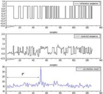
The distance menstruation shows the results of a simulated correlation menstruation. From high to bottom, the primary graphic shows a 1023 length PRBS, (for clarity considerations, we have a tendency to solely show the primary 127 chips of the total sequence), this sequence is that the reference code. The second graphic depicts a simulated received sequence (time delay and Gaussian noise were added). The last graphic shows the results of the correlation between the reference code and also the simulated received sequence. On the last graphic we are able to see a peak of correlation.
The position of the height corresponds to the delay that we have a tendency to introduce. Results of correlation between a 1023 chips PRBS and a simulated received sequence to perform obstacle detection with this measuring system, we have a tendency to solely ought to localize the correlation peaks, between the emitted code and its echo. Thus, a peak within the correlation graphic denotes a detected obstacle whose distance d to the detector is given by d = v л/2 Where v is that the wave speed and л is that the time delay. On the correlation measuring system diagram, the correlation unit is connected to an indication process unit.
Figure 1.2 Result of correlation between a 1023 chips PRBS and simulated received sequence.
The correlator provides real time values of correlation result to the signal process unit. The latter performs obstacle detection and provides the space to the obstacle in real time.
4. Radar Reflections from Flat Ground
of targets at low heights, a mirrored image at the Earth's surface is critical. This is often potential providing the ripples of the realm among the primary physicist zone don't exceed the worth zero.001 R (i.e.: among a radius of a thousand m no obstacle could also be larger than one m!)
III.
CLASSIFICATION OF MEASURING INSTRUMENT
1. Pulse measuring instrument
Pulse measuring instrument transmits a sequence of short pulses of RF energy. By activity the time for echoes of those pulses scattered off a target to come back to the measuring instrument, vary to the target are often calculable by the heart beat measuring instrument. The live parts of pulse measuring instrument area unit transmitter, consisting of associate degree generator and a pulse modulator. The antenna system that passes magnetism energy from the transmitter to the transmission medium, and receives reflection from the target. The receiver, that amplifies the signal received by the heart beat measuring instrument and detects returns from target and Interfaces, together with displays and interfaces to different electronic systems shown in Figure four.4. Continuous measuring instrument
As opposition periodical measuring instrument systems, continuous wave (CW) measuring instrument systems emit electromagnetic wave in the least times. Standard CW measuring instrument cannot live vary as a result of there's no basis for the measure of the time delay. Recall that the essential measuring instrument system created pulses and used the quantity between transmission and reception to work out the targets vary. If the energy is transmitted incessantly then this may not be potential.
CW measuring instrument will live the fast rate-of-change within the target's vary. His is accomplished by a right away measure of the Doppler shift of the came signal. The Doppler shift may be a modification within the frequency of the non-particulate radiation caused by motion of the transmitter, target or each. For instance, if the transmitter is moving, the wavelength is reduced by a fraction proportional to the speed it's taking possession the direction of propagation. Since the speed of propagation may be a constant, the frequency should increase because the wavelength shortens. Worldwide Web result's associate degrees upwards shift within the transmitted frequency, referred to as the Doppler shift. RADAR sets transmit a high-frequency signal incessantly. The echo signal is received and processed for good
2. Doppler measuring instrument
Doppler radar microwave, radar microwave measuring device, radio detection and ranging, radiolocation, measuring instrument, measuring system, measuring device is specialized radar that produces use of the Doppler shift to supply speed and knowledge concerning objects at a distance. It will this by beaming a microwave signal towards a desired target and listening for its reflection, then analyzing however the frequency of the came signal has been altered by the object's motion. This variation offers direct and extremely correct measurements of the radial part of a target's speed relative to the measuring instrument. Doppler radars area unit employed in aviation, sounding satellites, police speed gun, and radiology. The particular term "Doppler Radar".
IV.
DOPPLER RESULT
The emitted signal toward the automotive is mirrored back with a variation of frequency that depends on the speed away/toward the measuring instrument (160 km/h). This is often solely a part of the $64000 speed (170 km/h).The Doppler shift (or Doppler shift), is that the modification in frequency of a wave for associate degree observer moving relative to the supply of the waves. It’s ordinarily detected once a vehicle sounding a siren approaches passes associate degreed recedes from an observer. The received frequency is hyperbolic (compared to the emitted frequency) throughout the approach, it's identical at the moment of passing by, and it's decreased throughout the recession. This variation of frequency conjointly depends on the direction the wave supply is moving with relation to the observer; it's most once the supply is moving directly toward or removed from the observer, and diminishes with increasing angle between the direction of motion and also the direction of the waves, till once the supply is moving at right angles to the observer, there's no shift. Since with electromagnetic wave like microwaves frequency is reciprocally proportional to wavelength, the wavelength of the waves is additionally affected. Thus, the relative distinction in speed between a supply associate degreed an observer is what offers rise to the Doppler shift.
V.
CORRELATION RADAR
The most necessary measuring instrument employed in this project is correlation measuring instrument whose perform is to supply the matching between transmitted and received signal and also the matched signal is send to comparator for comparison the info Digital lay correlation perform is given higher than .The classical correlation is that the total of sample product X and Y, with Y being solely shifted in time. Zeros replace gaps within the shifted sequence.
cyclic correlation perform a circular permutation of the second sequence.
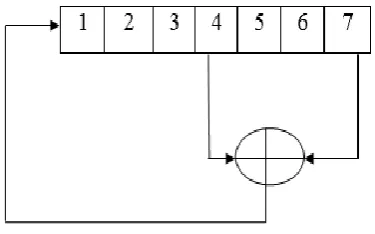
Pseudo random sequences are often unipolar or bipolar. For unipolar sequence, chips will take the worth zero and one once a bipolar sequence will have values -1 or one. We used unipolar sequences and this sequence is generated by victimization register. Pseudo random binary sequences area unit generated victimization some specific outputs of the register's flip flops area unit fed-back via a XOR circuit.
This feedback is completed in order that the register plays its (2n-1) potential states, like n is that the range of flip-flops forming the register. Thus, we tend to get what's referred to as a most length sequence.
𝐶𝑥𝑦(𝑘) = 𝑥 𝑖 𝑦(𝑘 + 𝑖) 𝑁
𝑖=0
Where Cxy is that the correlation, N is that the range of samples and k is that the time shift.
VI.
PRBS
PRBS or Pseudo Random Binary Sequence is primarily a random sequence of binary numbers. It is random in a sense that the worth of associate degree component of the sequence is freelance of the values of any of the different components. It is 'pseudo' as a result of it is settled and when N components it starts to repeat itself, in contrast to real random sequences.
Figure 1.4.Binary Pseudo Random Sequence Generator
Examples of random sequences area unit radioactive decay and white noise. A binary sequence (BS) may be a sequence of N bits, a j for j = zero, 1... N − 1, i.e. m ones and Nm zeros. A binary sequence is pseudo-random (PRBS) if its autocorrelation perform, has solely 2 values. PRBS is enforced exploitation LFSR or Linear Feedback register. LFSR is associate n-bit register that pseudo-randomly scrolls between 2^n-1 values, however will it terribly quickly as a result of theirs stripped-down combinatory logic concerned. Once it reaches its final state, it'll traverse the sequence precisely as before.
VII.
PAST WORKS
implementation of an obstacle detection, obstacle dodging and anti-collision system employing a COTS multi-beam forward wanting asdic. The aim is to equip our in-house engineered MEREDITH autonomous underwater vehicle the aptitude to navigate around obstacles that arise in its programmed path. For a system, the flexibility to spot unknown obstacles and discards false returns and noise is a very important issue and intensely difficult. To get rid of this drawback, image process technique is used to extract potential obstacles from the asdic image. This is follow by the employment of a time period multi-frame filter to make sure the presence of obstacles. Lounis Douadi, Pascal Deloof [5] et all projected an automotive anti-collision systems the principle of this method is to avoid collision between the equipped vehicle and also the one ahead, or alternative quite obstacles (pedestrians, animals, etc.). As a consequence, this may cut back accidents and enhance road safety. Correlation radar microwave, radar microwave measuring device, radio detection and ranging, radiolocation, measuring instrument, measuring system, measuring device is that the most up-to-date radar used for anti-collision system. He conjointly provides plan concerning the principle of distance activity exploitation this sensing element additionally because the implementation of the correlation perform on associate FPGA. Chika Sugimoto, Yasuhisa Nakamura,[6] and Takuya Hashimoto propose a model pedestrian-to-vehicle communication system that uses a telephone and wireless communication to enhance the security of pedestrians. A pedestrian-to-vehicle communication system was developed by employing a telephone and an automotive navigation system equipped. With GPS and wireless communication perform essentially the provide the thought concerning it the exchange of data between a telephone and an automotive navigation system and create every of a pedestrian and a driver notice the opposite from out of sight. L. Sakkila [7] - P. Deloofet all projected a method real time process unit used for associate anti-collision road measuring device system. This measuring device supported a numerical correlation between the transmitted signal and also the received signal. The signal uses orthogonal codes to make sure a multiple access communication between all vehicles in close to space. This method used the pseudo-random sequences and a correlation receiver is extremely helpful to find signal buried in noise within the anti-collision measuring device field. The pseudo-random sequences area unit desirable because of the easier modulation of the measuring device wave form they involve and their hardiness. This makes sure that the projected receiver is economical and straightforward to implement. C. Tatkeu, P. Deloof [8] et all projected a way for improve liableness, security on roads .In this technique cooperative been developed to facilitate the exploitation of automatic collision dodging measuring device that uses an electrical device within targets.
VIII.
CONCLUSION
We have delineate the principle of a distance activity with correlation radar microwave, radar microwave measuring device, radio detection and ranging, radiolocation, measuring instrument, measuring system, measuring device and gave our contributions on real time implementation of this radar. Several enhancements were performed on the correlator design. This issues optimized multipliers and enhancements on adder layers. A specific attention was paid to our correlator generator. The foremost interest of the latter is that it's able to generate the VHDL code of the correlator together with all its parts, in associate automatic approach.
REFERENCES
[1]. Yuki Nakanishi, Ryohta Yanaguchi “A New Collision Judgment Algorithm for Pedestrians –Vehicular Collision Avoidance Support System in Advanced ITS” IEEE Networking and Services, no-6, pp.103-106, Mar.2010
[2]. Pravin P Ashtankar, Sanjay S. dorle, “Design Approach for Anti-Collision Mechanism between vehicle to Vehicle for improving Safety operation in Intelligent transportation system, IMECS, vol.2, page.1-4, March 2009
[3]. Hung Youpeng, Zhang Haibo, “Radar Infrared sensor Track Correlation Algorithm Using Gray Correlative Analysis” IEEE Computer Society Washington, pp.707-710,Apr. 2009
[4]. Obstacle detection, obstacle avoidance and anti-collision system using a COTS multi-beam forward looking sonar proposed by Ken Toe, Kai Wei Ong and Hoe Chee Lai, IEEE OCEANS, PP.1-10, Oct. 2009
[5]. Lounis Douadi, Pascal Deloof, Yassin Elhillali “Real time implementation of reconfigurable correlation radar for road anti-collision system” IEEE Industrial Technology, pp.1-7, Apr. 2011
[6]. Chika Sugimoto, Yasuhisa Nakamura, Takuya Hashimoto ”Development of pedestrian-to-vehicle communication system prototype for pedestrian safety using both wide-area and direct communication, IEEE AINA, no.22, pp.64-69, Mar. 2008
[7]. L. Sakkila, P. Deloof. Real time processing unit used for an anti-collision road radar system, IEEE Industrial Technology, pp.1-7, Apr. 2008
[8]. C. Tatkeu, P. Deloof, Y. Elhillai “A Cooperative radar system for collision avoidance and communication between vehicles” IEEE Intelligent Transportation Systems, pp.1012-1016, Sept. 2006
[9]. Retro-directive Noise Correlation Radar with Extremely Low Acquisition Time Shalabh Gupta and E. R. Brown. IEEE Microwave Symposium Digest, vol.1, pp.599-602,June. 2003.
[10]. M .Lienardand P. Degauque “Correlation Radar: An optimization of code generator architecture vol.39, no.19, pp.1-2, Apr. 2003.