Abstract— Driving simulators are used in the automotive industry to prove new systems and evaluate the driver’s behaviour and interaction with the vehicle. The DRIVAS S IS T simulators combine haptic, visual and acoustic cues in order to immerse the driver into a sufficient degree of realism. The goal of this paper is to present aspects concerning the simulation and validation of a control strategy for a motion driving simulator which includes the dynamical models of the human vestibular system. It is proved that by introducing the motion perception of the driver, the workspace required for actuating the driving simulator is reduced.
Index Term— driving simulators, vestibular system, real time simulations, control.
I. INT RODUCT ION
There is a large variety of driving simulator designs available, depending on the application that they serve. Nevertheless most driving simulators are built with the same goal: to immerse the driver to a certain extend into the simulation environment. One of the most challenging tasks when designing a driving simulator is its validation. There are two major aspects in a simulator validation approach: the model validation of the simulated systems (vehicle dynamics) and the driver’s response to the offered environment. Understanding the driving task and the implication of decision making for the driver is still challenging.
The driving task was often approached in literature as a visual guided task [1]-[3]. It was proved however that the drivers use other factors when steering their vehicle [4]-[5].
Durkee characterized the driving perception task using the speed and following distance estimation by the driver (predetermined by the researchers) and the adjustment of the speed or distance using the simulator’s facilities (pedals, steering wheel, etc) and underlined the importance of understanding the human perception and ego motion [6].
Visual channels are used by the human while driving a car in order to collect different information about the driving
T his work was partially done in the frame of the Project PRODOC ID 7676 as part of a doctoral joint cooperation.
A. Capustiac is a PhD student at the University of Duisburg Essen; Germany; phone: +49(0)203-379-2901; fax: +49(0)2033794494; e-mail:
B. Hesse is a PhD student at the University of Duisburg Essen; Germany; e-mail: [email protected].
D. Schramm is with the Department for Mechatronics as Professor, University of Duisburg Essen, Germany; e-mail: [email protected].
D. Banabic is with the Department of Manufacturing T echnology as Professor, T echnical University of Cluj-Napoca, Romania; e-mail:
environment [1]. Experimental studies showed that driving skills are significantly affected by the vestibular system [7]-[8]. This contribution proposes a low cost actuation solution and presents the development of a control strategy that includes both vehicle dynamics and human motion perception models.
II. DRIVING SIMULAT ORS FOR HUMAN-MACHINE-INT ERFACE ST UDIES
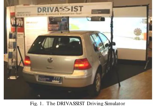
Due to the work being conducted on advanced driving assistance systems (ADAS) at the Chair of Mechatronics at the University of Duisburg-Essen, a tool was developed to test ADAS in combination with a real driver in the loop. The driving simulator DRIVASSIST provides good results for high-way like traffic scenarios as already stated in [9].
The DRIVASSIST simulator combines visual, acoustical and haptic cues submerging the driver into a sufficient degree of realism with the help of visualization of driving situations and scenarios through screens, engine sounds simulated with loudspeakers, a force-feedback steering wheel, force-feedback pedals and steering torque.
By combining inertial, visual and acoustic cues, driving simulators are the proper tools to test and develop vehicle
systems and to study the human–machine–interface (HMI). Perception of the motion is defined as the interpretation of the sensory information by the human, while ego motion represents the motion of the body in the space [5]. The motion is sensed by the human through the balance organs in the ear and skin and by judging the acceleration through skin pressure.
The vestibular system is responsible of controlling the equilibrium and motion senses in the human body. Its role is
A Human Centered Control Strategy for a
Driving Simulator
A.
Capustiac, B. Hesse, D. Schramm, D. Banabic
to transfer information about the accelerations and rotations applied on its body [4].
In a driving simulator, the visual cues are introduced with the help of a graphic system. The optical flow is the most investigated cue in the motion research [5]. It is defined as the motion experience while running, driving, and walking. This effect is accurately perceived by the human brain, helping to control locomotion and continuous movement towards the destination. Jamson proved in [10] that for correct speed perception in a driving simulator, a horizontal view of at least 120° is required.
The DRIVASSIST simulators therefore are designed to give the driver at least that required field of view. The architecture enables the user to set up a modular simulator. Monitors (or projectors) can be added easily, so that a 360° field of view can be reached. The visualization of the environment is done with the help of a commercial game engine. This ensures a high level of realism and an easy adaption of scenarios.
Rendering of the hearing cues in a driving simulator can increase its degree of realism. Different sounds can be simulated in a driving simulator: engine sounds based on current engine states, wind sounds, horns, sirens, etc. The engine and road sounds can increase the fatigue of the driver, together with the vibrations introduced in the simulator and they are one important piece of information about the vehicle state. The acoustic set up in DRIVASSIST simulators meet the needs of a modern game. The used game engine enables a 3D sound of vehicles, the environment or triggered sound -emitters. This can not only be used to create a realistic vehicle sound, but it can also be used as a human–machine–interface device.
The haptic perception refers to the tactile awareness through the skin and kinaesthetic perception of the position and motion of the joints and muscles [5], [11]. Besides vibrations of the vehicle, the design of surfaces within the cockpit of a driving simulator and the characteristics of the steering systems and the pedals are important factors.
Especially the steering characteristics have been addressed during the development of the DRIVASSIST simulators. A multi-body model is used to derive the steering wheel torque in real-time and a DC motor is then used to generate exactly that torque at the steering wheel. This force-feedback steering wheel has already been used during the design of lane-keeping
assistance systems and other studies and its realism has been shown during these studies [9].
III. DEVELOPMENT OF AN ACT IVE DRIVING SIMULAT OR
The manoeuvres analyzed with the help of the static driving simulator had a moderate vehicle dynamic nature and therefore no vehicle movement was needed for a realistic impression. However, modern driver assistance systems are getting more and more complex. Assistance for longitu dinal and lateral vehicle guidance is combined. Additionally, modern assistance systems also cover guidance as well as stabilization tasks.
A static simulator therefore is not fully sufficient to evaluate the performance of assistance systems for all relevant driving manoeuvres. In order to expand the simulation scenarios to more complex manoeuvres, e.g. driving on country roads and in the city and to evaluate corresponding assistance systems with such manoeuvres, an active driving simulator is required to offer a more realistic driving experience to the driver. This paper therefore focuses on the development of such an active simulator.
Different actuation mechanisms are used and described in the specialized literature. The parallel Stewart platform with 6 Degrees of Freedom (DOF) is widely used. The fidelity of a driving simulator increases with the number of situation reproduced that occurs also in reality. For this reason, it is assumed that a high level simulator offers a more realistic experience as a mid-level simulator [14]. However, Denne stated in [15] that the roll, pitch and heave motion are normally sufficient for simulators.
The driving simulator is designed in order to use three DOF, roll, pitch, and heave. The DOF are realized by vertical excitation of the wheels through hydraulic actuators. Although the DOF and the workspace of the simulator are limited, it will resituate a sufficient sensation of movement as closely as the one sensed in a real vehicle for the planed driving scenarios. This solution was chosen with respect to the simplicity of the design, type of psycho-physic studies to be carried out and the global costs.
The main goal of the motion simulator is to combine two major motion aspects [18]. The first one is the road excitation which can be introduced to each wheel by means of hydraulic actuators so that the actuators displacements (higher frequency) are very similar to the profile of the original road surface [13]. The second aspect is to impose a defined motion (low frequency) to the vehicle body (inverse model). Since not only road excitation, but also the roll, pitch and heave motion of the simulator is to be controlled, the dynamic transfer path in between the actuators and the vehicle body has to be understood.
The ride of vehicles on different road categories is accompanied by the permanent presence of shocks and vibrations.
These vibrations have different effects on the human organs. The vestibular system is sensitive to accelerations and less to the frequency of the vibration [12]. The frequencies of the vibrations have a great influence on the organ of Corti, and the effect increases with the frequency. Thus introducing the road characteristics and the road response in the driving simulator will resituate a proper driving feeling.
The road profiles were modelled by implementing in MATLAB/Simulink the following equation [13]:
̇ ( ) ( ) √ ( ) ( ) (1) where ( ) is defined as the road unevenness (roughness), and ( ) is the white noise signal. For simulation purposes a white noise Simulink block with noise power 1 was used. The lowest cut off angular frequency is described as:
(2)
The data used in simulations are given in Table I.
Figure 3 shows the road profile obtained for a vehicle driving with 10 m/s velocity over a B category road.
IV. INT ENDED CONT ROL WIT H T HE INVERSE DYNAMICS
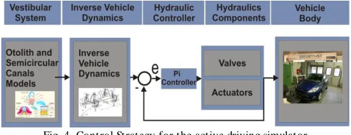
In order to be able to study the interaction between the hydraulic actuators and the vehicle, a simulation model is needed. Figure 4 describes the simulation steps implemented. The goal is to obtain a control strategy using the inverse dynamics of the vehicle combined with a PI controller of the hydraulic valve and with the human vestibular system model. For model validation, the IPG Car Model was used. This software allows performing different and complex makeovers [16]. For test purposes, angles and body movements were given as input to the system. The desired actuators strokes are calculated. In order to have an actual stroke, the hydraulic actuators were modelled and used for the PI valve controller. The aim of imposing a certain movement on the vehicle body is to relate certain driving makeovers to imposed forces on the human body while driving.
A. Vestibular System Modeling
The vestibular system has two parts: the semicircular canals and the otolith. The semicircular canals are three tubes that control the human body’s sense of balance. These canals are positioned perpendicular to each other, permitting them to perceive the possible motions in an R3. The fluid inside the canals moves as the body moves, bending the hairs inside the channel and enabling the brain to determine the movement of the body through the space, depending on the excitation level of the sensorial cells [5].
The otolith senses the linear motion. This organ transmits information about specific forces detected by the human body to the brain. The specific forces are defined as a relation between the translational acceleration and the gravitational vector. The two organs in the human ears (utricle and sacule) detect the horizontal and vertical motion [4].
As stated before, the motion simulator has 3 DOF. For this reason, the dynamic modeling was performed only for roll, pitch and heave motion. In order to obtain the sensed ang ular velocity by the driver, the following transfer functions were implemented:
( )
( )( ) (3)
Respectively: ( )
( )( ) (4)
In order to find the sensed linear acceleration, the dynamics
of the otolith was used:
( ) ( )
( )( ) (5)
The values for the parameters are given in Table II [7].
The semicircular canals are modelled as a system where by inputting the angular acceleration, the subjective sensation of angular velocity is obtained. The otolith is modelled as a system where inputting the specific force, the output obtained is the subjective sensation of tilt and linear velocity.
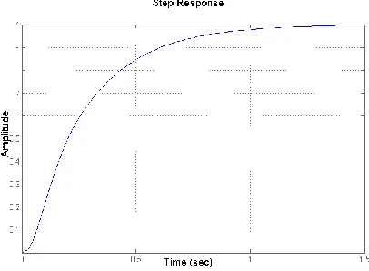
Figure 5 shows the step response of the cupula for the roll semicircular canal. The cupula is placed within the membrane of the ampullae of each semicircular canal. The role of the
Fig. 4. Control Strategy for the active driving simulator
TABLEI
SIMULATION ROAD PROFILES [23]
Road Class Parameters Value Units
A (very good) Gq(Ω0)- roughness coefficient
B (good) Gq(Ω0)
C (average) Gq(Ω0)
D (poor) Gq(Ω0)
E (very poor) Gq(Ω0)
All n0 0.1 [cycle/m]
Fig. 3. Road profile modeled for a vehicle driving on a B road category
TABLEII
SIMULATION VESTIBULAR SYSTEM DATA [7]
Motion Parameters Value Units
Roll 6.1 [s]
Pitch 5.3 [s]
All 30 [s]
k 0.4 -
13.2 [s]
5.33 [s]
ampullae is to allow the interaction between the utricule chamber and the semicircular canals. The role of the cupula is to transmit the excitation of the hair cells while the fluid passes it, through a signal to the brain. Van Egmond defined the step response of the cupula as the subjective cupulogram in [20]. It was called so because it records the time of sensation reported by the human. Physically the membrane of the semicircular canal is being deflected, and then under the influence of its own elastic torque it returns to the initial form.
Figure 6 shows the bode diagram of the semicircular canals transfer function for the rotation about roll axis. In the 0 - 20 rad/s range (0 Hz to 3.18 Hz) the subjective sensation is that of the angular velocity of the motion inputted. The same observation was made in [4]. Meiry also noted that while a rotation with constant angular velocity is not perceived by the semicircular canals, a constant angular acceleration motion is sensed over time so the perception coincides with the instantaneous angular velocity of the motion applied on the human.
B. Inverse Vertical Vehicle Model
The first step in realizing relevant motion or forces is to use the derived inverse dynamic vehicle model and impose certain movements. In order to obtain the strokes of the actuators, a simplified vehicle model is used as an approach to the real vehicle. The model consists of 5 bodies, the chassis and the wheels combined with the wheel carriers. The wheels are only allowed to move in vertical direction. The vehicle chassis is supported through spring and damper elements. The spring s and dampers are massless elements and are attached to the wheels and the vehicle chassis as shown in Figure 7. The steering system is not used in this set up [18].
The inverse dynamics of the comfort model determines the
strokes of the actuators ( ) for different imposed roll pitch and heave motion ( ) of the vehicle body and is described by the following equations:
( ̈ ( ̇ ̇ ) (
)) ( ) (6) The velocity of the wheel centre is calculated:
̇
( ̈ ( )) ̇ (7)
The vertical position of the suspension attachment point at the chassis is defined as :
̇
(8) The unload spring length of the tire suspension is:
( )
( ) (9)
And respectively the unload spring length of chassis suspension:
( )
( ) (10)
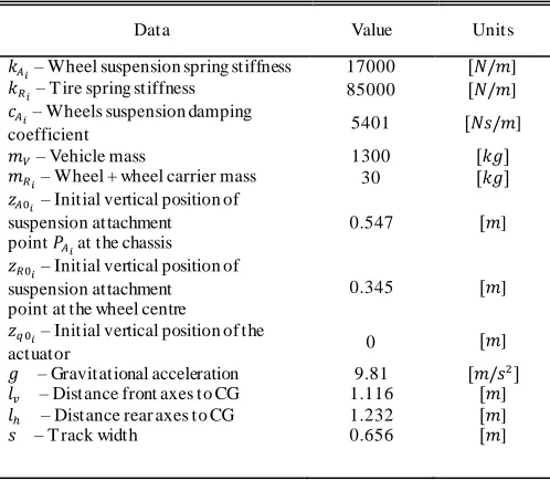
All parameters used in the simulations are given in Table 3.
Fig. 7. T he vehicle comfort model used in simulations
Fig. 5. T he step response of the transfer function for roll motion
C. Hydraulic Actuator Model
In order to be able to implement a fairly simple control strategy, the hydraulic parts were modelled. The following equation describes the model of the servo valve dynamics, written as a second order model of the form:
̈ ̇ ( ̇ ) (11)
where is the normalized servo valve position, ̇ is the velocity, ̈ is the acceleration, is the valve input voltage and to maximum valve voltage (1 V), is a proportional factor, is the valve hysteresis, is the damping ratio and is the natural frequency [19]. The hydraulic cylinder model was obtained implementing the following equation of motion:
( ( ) ) (12)
where m is the total mass of the system, is the area ratio, and are the pressures in chamber A respectively chamber B, is the piston area, is the external load, is the friction force and is the piston’s acceleration. These equations are implemented in Matlab/Simulink.
The outputs of the system are the actual actuator positions. The overall hydraulic system consists of a differential cylinder subjected to a time varying load and a two stage servo valve supplied by a constant pressure from a fixed displacement pump. The setup is shown in Figure 8, where and are the piston and valve displacement. The pump supplies the system with a constant pressure . The hydraulic system inputs are the valve voltage and the external force . The system outputs are the pressures in both chambers and
and the position of the piston .
The next step is to implement a PI controller for the hydraulic valve into the system. The input of the controller is the signal , which is the difference between the desired actuator position and the actual actuator position and the output is the saturated controlled valve voltage of . The
output is send to the hydraulic model described by equations (11) - (12).
D. Direct Vertical Vehicle Model
For validation purposes, the direct vehicle model was developed with the help of the linearized NEWTON-Equation:
̈ ∑ ( ( ⏟ )
( ̇⏟ ̇ )
̇
)
(13)
The linearized EULER-Equations for the vehicle model are calculated as follows:
̈ (( ̇ ) (
̇ ) ( ̇ ) (
̇ )) (14)
̈ (( ̇ ) (
̇ )) (( ̇ ) ( ̇ )) (15) The NEWTON-Equations for the wheels are:
̈ ( ) ( ) ( ̇ ̇ ) (16)
E. Simulation results
While driving a vehicle, the human feels a complex sum of accelerations. In driving simulators, these accelerations are introduced with the help of inertial (motion) cues.
These accelerations are integrated over time to result in velocities and further integrated to produce displacements. There are two types of accelerations felt in the vehicle: the gravitational and the inertial ones (speed up, slow down, corners) [15]. It was proved that in encased environment the difference between the gravitational and inertial acceleration cannot be felt [6] and that accelerations and decelerations under 0.05 g are normally ignored by the human [4].
Each cue, taken separately is also important in simulating a real driving situation, but it is important to correctly combine them. For example, for convincingly reproducing the forward acceleration of the vehicle, the platform will be tilted backwards and the visuals will show forward movement and the appropriate sound effects for this manoeuvre will be provided. In the setup discussed in this paper, the vehicle itself acts as a mobile platform with 3 DOF.
TABLEIII
SIMULATION VEHICLE DATA [18]
Data Value Units
– Wheel suspension spring stiffness 17000 ]
– T ire spring stiffness 85000 ]
– Wheels suspension damping
coefficient 5401 ]
– Vehicle mass 1300
– Wheel + wheel carrier mass 30
– Initial vertical position of
suspension attachment point at the chassis
0.547 ]
– Initial vertical position of
suspension attachment point at the wheel centre
0.345 ]
– Initial vertical position of the
actuator 0 ]
– Gravitational acceleration 9.81
– Distance front axes to CG 1.116 ]
– Distance rear axes to CG 1.232 ]
– T rack width 0.656 ]
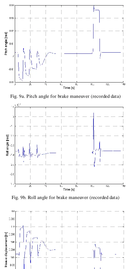
In order to test the controller proposed, the brake manoeuvre was simulated with the help of the IPG Car Maker. The recorded motion roll ( ), pitch ( ) and heave ( ) were inputted to the vestibular model. The sensed angular velocity and acceleration and linear acceleration were obtained from these models. Figures 9 show the recorded data.
For this manoeuvre, the vehicle first accelerates for 80 s and then brakes. The total time of the manoeuvre is 105 s.
Filtering these inputs thorough the transfer functions that describe the vestibular system, the sensed angular velocity and acceleration and the sensed vertical velocity and acceleration by the human driver could be obtained. It was observed that the amplitudes of the output signals were reduced with maximum 10% from the inputted signals. Figure 10 shows the sensed pitch angular velocity by the human driver while breaking [16].
With the help of these results, the driver’s motion sensing in a car can be analyzed.
It is crucial to know the values of the accelerations sent by the human in a vehicle in order to be able to filter these signals and implement them in the motion cueing algorithms. In [21] the gain for the proposed model remained constant, in the range of normal head movements from 0.1 to 1.0 Hz, with the phase close to zero degrees. It was showed that in this frequency range, the otolith functions as a specific force transducer.
The data obtained from the vestibular system model were inputted in the inverse vehicle model. It was possible to obtain actuators strokes with respect to the driver’s perception model. Figure 11 shows two sets of strokes for the four actuators.
The first set (q1-q4) are the strokes obtained while inputting to the inverse vehicle model the data recorded with the help of IPG Car maker (roll, pitch and heave). In the second set (qf1 -qf4), the strokes are obtained by introducing in the inverse Fig. 9a. Pitch angle for brake maneuver (recorded data)
Fig. 9b. Roll angle for brake maneuver (recorded data)
Fig. 9c. Heave displacement for brake maneuver (recorded data)
Fig. 10. Pitch velocity obtained from the vestibular model
vehicle model the roll, pitch and heave data obtained from the vestibular system.
The amplitudes of the second data are smaller than the first. In this way it is shown that by including the vestibular system model it is possible to use a reduced working space.
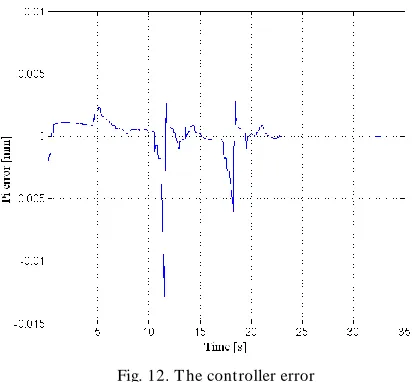
With the help of the inverse dynamic model, the actuators positions, velocities and accelerations( ̇ ̈ ) were calculated. To be able to study the error and the effect of the PI controller, the data presented in Figure 11 were used as desired actuator position for the control scheme presented in Figure 4. Values from were considered (front wheel left).
Figure 12 presents the error of the controller while running the simulation proposed in Figure 4.
The vehicle body is controlled with a feed forward control. In this contribution the vehicle body is substituted with a vehicle model. This enables an improvement of the control strategy without setting up the real system. The resulting vehicle movement is shown below.
The direct dynamic model described by the equations (13)-(16) was used for validation. The heave motion was considered. Figure 13 presents recorded heave motion with the
help of the IPG Car Maker and the heave motion obtained from the forward dynamics model. The results obtained from the simulations were satisfying.
Figure 13 clearly shows that the actual vehicle movement has the same characteristics and the same amplitude as the desired one. This implies that the first goal of the driving simulator, to provide the driver with realistic road excitation can be reached.
V. CONCLUSION
The results of this contribution show, that the desired vehicle body movement can be performed with the intended hydraulics setup. The inverse dynamics enable the calculation of needed piston movements in order to force a certain vehicle movement.
Driving simulators can offer means of analyzing the driver’s behaviour in a safe environment. The objective of this paper is to develop a control strategy that contains the driver’s perception of motion in a 3 DOF simulator. Using dynamics models, the interaction between driver and the simulator is studied.
The transfer functions implemented help understanding the human perception of motion. The mathematical models of the linear and rotational motion sensorial human organs show the acceleration values sent by the human while driving a manoeuvre. It was shown that by including the vestibular system model in the control strategy, the strokes of the actuators needed are smaller, while performing the same manoeuvre.
Fig. 12. T he controller error
REFERENCES
[1] D.N. Lee, “A theory of visual control of braking based on information about time-to-collision“. In Perception 5(4), 1976, pp: 437 – 459. [2] G. Reymond, A. Kemeny, J. Droulez, A. Berthoz, “Role of lateral acceleration in curve driving: driver model ad experiments on a real vehicle and a driving simulator“, 2001, In Human Factors, Vol.43. [3] T . Hadata, H. Sakata, H. Kusaka, “Psychophysical Analysis of the
Sensation of Reality Induced by a visual wide field display“. In SMPTE
Journal, 1980, August, Vol. 89, pp: 117-126.
[4] J. Meiry, T he vestibular system and human dynamic space orientation. PhD T hesis. Massachusetts Institute of T echnology, USA, 1958. [5] A. Kemeny, F. Penerai, “ Evaluation perception in driving simulation
experiments“ , In Trends in Cognitive Sciences, 2003,Vol. 7, No. 1.
[6] S.M. Durkee, T he effect of Simulation Attributes on Driver Perception and Behaviour, Master of Science T hesis, Montana State University, USA, 2010.
[7] S. Baron, R. Lancraft, G. Zacharias, Pilot/Vehicle Model Analysis of Visual and Motion Cue Requirements in Flight Simulation, NASA Report 3312, 1980.
[8] R. T elban, F. Cardullo, Motion Cueing Algorithm Development: Human-Centerde Linear and Nonlinear Approaches. NASA Report 213747, 2005.
[9] B. Hesse, G. Hiesgen, T . Brandt, D. Schramm, “ A Driving Simulator as a T ool for the early Characteristics Validation of Human -Centered Mechatronic Systems“. In Proceedings of VDI Mechatronik, 2009, pp: 109-116.
[10] H. Jamson, “ Driving simulation validity: issues of field of view and resolution“. In Proceedings of Driving Sim ulators Conference, Paris, France, 2000, pp: 57-64.
[11] A. Rydström, The use of haptics when interacting with in -car interfaces, Doctoral T hesis, Lulea University of T echnology, Sweden, 2009. [12] VDI 2057, Human exposure t o mechanical vibrations. Whole body
vibrations. Düsseldorf: Verein Deutscher Ingenieure.
[13] L. He, G. Qin, Y. Zhang, L. Chen, “Non-stationary Random Analysis of vehicle with fractional damping“, In Proceedings of The international
Conference on Intelligent Computation Technology and Autom ation,
2008.
[14] S.T . Godley, T .J. Triggs, B.N. Fildes, “Driving simulator validation for speed research“. In Accident Analysis and Prevention, Vol. 34, 2002, pp: 589-600.
[15] P. Denne, Simulators for leisure – A new industry. IEE Conference on Simulation, 1986.
[16] IPG Company, http://www.ipg.de/, November, 2010.
[17] V. T chermychouk, Objective assessment of static and dynamic seats under vehicular vibrations. Master Thesis, 1999, Concordia University, Montreal, Canada
[18] A. Capustiac, M. Unterreiner, D. Schramm, “ Actuation strategy for a new Driving Simulator Setu“ p. In The Journal of State Phenom ena. 2010, Vol: Robotics and automation Subsystems, pp: 166 -167. [19] C. Heckhoof, A. Albadawi, R. Germann, T . Brandt, M. Hiller, D.
Schramm, “Motion control of a large scale quadruped walking robot“. In
Proceedings of Multibody Dynam ics 2007.
[20] A.A. Van Egmond, J.J. Groen, B.W. Jongkees, “T he mechanics of the semicircular canal“. In Physiology, 1949, pp: 1-17.
[21] L.R. Young, “Perception of the body in space“, In The Handbook of
Physiology – T he Nervous System III, pp 1023-1006.
[22] M. Mauer, C. Stiller, Fahrerassistenzsysteme mit maschineller Wahrnehmung, s.l. :Springer Verlag, 2005.