Moment Method Analysis of Standard and Reduced
Height Broad-Wall Longitudinal Slot Doublets
in Rectangular Waveguides
1
Rintu K. Gayen,
2Sushrut Das
1,2Dept. of Electronics Engg., Indian School of Mines, Dhanbad, Jharkhand, India
Abstract
This paper presents a method of moments based analysis of standard and reduced height a broad-wall longitudinal slot doublets antenna using Multiple Cavity Modeling Technique
(MCMT). Theoretical data for reflection coefficient, transmission coefficient, resonance length and resonance conductance have
been obtained. The theoretical data have been compared with experimental data and Ansoft HFSS’s simulated data to validate the proposed method. The excellent agreement obtained between the results validates the analysis.
Keywords
Waveguides, Slot Antennas, Moment Method, Reflection Coefficients, Transmission Coefficients, Normalized Admittance, Resonance.
I. Introduction
Waveguide based slot antennas are extensively used in array
antennas in ground based, air borne and ship borne radars in various frequency bands ranging from 1 GHz to 1000 GHz due to their large power handling capability, generation of ultra low side lobes and excellent polarization characteristics. Slots milled on the broad wall are capable of giving vertical and horizontal polarization, depending on its location and orientation on the broad wall of a rectangular waveguide. Front-fed reflector or cassegrain antenna systems suffer from gain reduction, due to
aperture blockage due to feed structure. Slot arrays do not suffer
from this drawback. Moreover, such arrays can be fabricated with minimum power loss compared to the case of reflector antennas. Due to these characteristics, the waveguide-fed slots have found
an important place in the array antennas as radiating elements. Studies on waveguide broad-wall longitudinal slot antennas date back before World War II. Till then a number of workers have carried out considerable investigations on the admittance properties of the structure and a detail review of it will be a literature of its own. A brief survey of these literatures has been provided in [1].
In addition to that, Datta, Chakraborty and Das [2] analyzed of
a strip loaded resonant longitudinal slot in the broad wall of a rectangular waveguide. In this paper a longitudinal slot at the centre of the broad wall of a rectangular waveguide in the presence of one or two vertical strips was analysed. The combination is excited
by the dominant TE01 mode, and the slot radiates externally. The effect of finite thickness of the waveguide walls was taken care
of by treating the slot as a stub waveguide. The coupled integral equations were solved using Galerkin’s technique. The resultant
coefficients were used to compute the dominant mode scattering
parameters and hence the equivalent T-network. The possibility of obtaining a resonant condition for the radiating centred slot strip combination was established. Design data derived in this study eliminate the need to gather initial input data experimentally.
Matzner and Amir [3] presented efficient moment method solution
for a longitudinal slot in a rectangular waveguide. In this paper
longitudinal slot in a rectangular waveguide was solved by the
moment method, where the transverse variation of the tangential electric field on the apertures of the slot contains the correct edge
behaviour. It was shown that three expansion functions are enough for an excellent convergence and accuracy of the solution. Kim and Eom [4] presented mode-matching model for a longitudinally slotted waveguide array. In this paper a mode-matching model for a longitudinally slotted waveguide array was presented. Fourier transforms and residue calculus were applied to obtain fast convergent series solutions. This model accurately estimates the radiation patterns of a longitudinally slotted waveguide array without a heavy computational burden. Kim and Eom [5] also presented radiation from longitudinal slots on the narrow wall of a rectangular waveguide. In this paper radiation from longitudinal slots on the narrow wall of a rectangular waveguide was studied. The mode-matching technique was used to obtain a system of
simultaneous equations for modal coefficients. Computations were performed and compared with measured data at 9.375 GHz. Montisci and Mazzarella [6] presented effect of the longitudinal component of the aperture electric field on the analysis of waveguide
longitudinal slots. In this paper Method of moment analysis of longitudinal radiating slots in the broadwall of a rectangular waveguide required a careful choice of the basis functions. This is particularly true when we need an accurate evaluation of both
longitudinal and transverse components of the Electric field on a slot with finite wall thickness. It was shown that entire-domain, two-dimensional, sinusoidal basis functions are a successful choice
for an accurate and effective modeling of a radiating slot cut in a thick waveguide wall. In this communication there focused focus
on slender slots, which ensure high polarization purity. If a very accurate array design is required, the effect of the longitudinal component of the Electric field, often neglected in the analysis of a narrow longitudinal slot, was shown to have a significant influence on the slot radiating and circuital properties.
Immediately after finding the interesting properties of a broad-wall longitudinal slot as radiating elements, studies were carried on finding the properties of slot doublets. Soon it was found that slots
milled on the opposite broad walls of a rectangular waveguide can provide two radiation nulls and otherwise Omni-directional radiation pattern. Initial reports on the resonance characteristics
of these structures [7, 8] were based on experimental results.
A theoretical description remained unavailable. Later Sangster
and Wang [9, 10] presented theoretical results on the resonance
properties of Omni-directional slot doublets in rectangular waveguides. In these papers moment method was employed to
analyze a longitudinal slot doublets in both air-filled and dielectric-filled rectangular waveguides in which the slot radiators were
located in the opposite broad faces of the waveguide. An analysis procedure for arrays of waveguide slot doublets based on the full T-network equivalent circuit representation of radiators was presented by Coetree and Joubert [11]. Later Mondal and
Chakraborty [12-13] presented a new configuration of a waveguide
offsets with respect to the waveguide center line. They studied and presented the resonance and radiation properties of the structure.
In this paper a moment method analysis of standard and reduced height a broad-wall longitudinal slot doublets antenna in rectangular waveguides are presented based on Multiple Cavity Modeling Technique (MCMT). The methodology involves in replacing all the apertures and discontinuities of the rectangular waveguide
based structures, with equivalent magnetic current densities so that the given structure can be analyzed using only Magnetic Field
Integral Equation (MFIE). To make the MFIE applicable to the
generalized waveguide structure problems, the given structures
are modeled using rectangular cavities. As it is necessary to use a number of such cavities in order to study these complicated
waveguide structures, the present method is named as Multiple
Cavity Modeling Technique (MCMT). The interfacing apertures
between different regions (waveguide – cavity, cavity –half space)
are then replaced by equivalent magnetic current densities. By applying the continuity condition of the tangential magnetic
field at the interfacing apertures, and expanding the unknown
magnetic current densities in terms of entire domain sinusoidal
basis function by using the Method of Moments, the problem is
reduced to solving the simultaneous linear equations.
II. Problem Formulation
The 3D view of a broad-wall longitudinal slot doublet is shown in fig. 1. The corresponding cavity modeling and details of magnetic current at the apertures are shown in fig. 2 respectively.
Fig. 1: Three Dimensional View of Waveguide Slot Doublets Proposed Antenna Structure
Fig. 2: Details of different regions and magnetic currents at the
apertures of a waveguide slot doublet.
The electric field at the slot may be assumed to be X-directed
and can be expressed in terms of a sum of weighted sinusoidal
basis functions, i, p z
e
defined over the entire length of the slot asfollows:
Where i,
p z
e
is defined as:(
′ ′ ′ =)
π(
′ +)
i p,z
p
sin z L On aperture "i"
e x , y ,z 2L
0 Elsewhere
Where 2L is the slot length, 2W is the slot width and 2b is the guide height. With the given electric field distribution the magnetic
currents can be obtained using equivalence principle.
At the region of slot, the tangential components of the magnetic field should be identical. This will give
( )
+( )
−( )
−( )
= wvg 1 cav1 1 cav1 2 wvg 3 incz z z z z z z z z
H M H M H M H M H (1)
( )
( )
( )
− cav1 1 + cav1 2 + uhs 2 =
z z z z z z
H M H M H M 0 (2)
( )
−( )
−( )
+( )
= wvg 1 wvg 3 cav2 3 cav2 4 incz z z z z z z z z
H M H M H M H M H (3)
( )
( )
( )
− cav2 3 + cav2 4 + lhs 4 =
z z z z z z
H M H M H M 0 (4)
The magnetic field scattered inside the cavity region due to the
source is determined by using cavity Green’s function of the electric vector potential. The cavity Green’s function has been derived by
solving the Helmholtz equation for the electric vector potential for unit magnetic current source. The scattered field inside the
waveguide due to slots in the broad wall of the waveguide also has been derived using the Green’s function for the electric potential
for such a slot. From the field existing at the apertures fed by the waveguide, the radiated field can be derived using plane wave spectrum approach. The radiated field is obtained by expanding
the spherical waves in terms of plane wave spectrum in the vector potential formulation.
The field components are given by
( )
(
)
(
)
( )
( )
( ) ∞ ∞ = −∞ −∞ + − = − × π η − − π − π ∑
∫ ∫
x z 2 2 Mlhs uhs i i z
z z 2 p,z 2 2 2 1 / 2
p 1 x z
z
z j k x k z
x 2 x z
z
k k
WL
H M E
k k k k
j sin k L for p even cos k L for p odd
sinc k W e dk dk
2Lk p 1 2 p
( )
( )
( )
(
)
(
)
(
)
(
)
(
)
(
)
Mwvg i i m n
z z p,z 2
p 1 m 0 n 0 mn w 2 2 2 mn mn j W
H M E
2k ab
cos n cos m x a
2a 1 S p
m m n
sinc W cos x a cos y b
2a 2a 2b
p p
k sin z L
2L 2L
sinh z for p even
cosh z ∞ ∞ = = = ε ε = × ηγ π π + × + π π π + + × π π − + + − γ γ
∑ ∑∑
− β
π
= −
inc j z
z x
H j sin e
2a
( )
{
}
(
)
(
)
(
)
{
}
{
(
)
}
(
)
{
}
{
(
)
}
2 Mcav i i 2
z z 2 p,z p 1 m p 1
m0 m0
m0 m0
m0 m0
j m
H M E k
2L k
1 sin m z L cos n x W
sin 2 t 2L 2W
cos y t cos y t y > y
cos y t cos y t y < y
∞ = = = ωε π = − × π π + + × Γ Γ Γ − Γ ′+ ′ ′ ′ Γ − Γ +
∑
∑
Where 2a is the guide width, 2t is the slot / waveguide wall thickness,xw is the sot offset from the center of the waveguide
and S p( )= πp (2Lγmn)
Rests of the symbols have their usual meaning. The method of moments is applied with Galerkin’s specialization [14] to obtain 2M different equations from the boundary conditions to enable
determination of theEip z, . The weighting function wq zl, (x y z, , )are defined as follows:
(
)
= π(
+)
l q,z
q
sin z L On aperture "l"
w x, y,z 2L
0 Elsewhere
for all q (q = 1, 2, 3, …….., M). After taking moment of each of the terms in boundary conditions (1) – (4), with l
q,z
w , we obtain
a set of simultaneous equations which upon solving gives the
unknown basis coefficients. The (p, q)th elements of the moment
matrices can be derived as follows:
( )
( )
( ) ( )
(
)
( )
(
)
(
)
(
)
∞ ∞ = = −γ ε ε = × ηγ + π + γ − δ + γ + × γ γ ∑∑
mn 2 wvg i l m np,z z q,z 2 2 m 0 n 0 mn
2 2 2 mn L 2 pq 2 mn mn mn
j W 1
H M ,w
k ab 1 S p
2S p S q k p
k L e
2L 1 S q
sinh L for p, q both even
cosh L for p, q both odd
0 otherwise
(
)
( )
× π + π ≠ 2 w1 if i=l m
cos x a cos n if i l
2a
where δpq is the Kronecker delta function.
( )
{
}
(
)
∞ = = = ωε π = − × ′ Γ ′ Γ Γ ≠∑
2cav i i 2
p,z z q,z 2
m p q 1
m0
m0 m0
j m
H M ,w k
2L k
cos 2 t if y = y 2LW
sin 2 t 1 if y y
( )
(
)
(
)
(
)
π π θ= φ= = − × λ η − θ φ × θ φ θ φ π π θ φ − π ∫ ∫
2 2 lhs / uhs i lp,z z q,z vis. reg. 2 / 2 2
2 2 0 0 2 2 2 16W L
H M ,w
1 sin cos
sin Lk sin cos for p, q both even cos Lk sin cos for p, q both odd
0 otherwise p q 1 2Lk sin cos
2 2 p
(
)
× θ φ − π θ φ θ θ φ 2 22Lk sin cos 1
q sinc Wk sin sin sin d d
(
)
(
)
(
)
2 2 lhs uhs l
p,z q,z invis. reg. 2 2 2 2 0 0 2 2 2 16W L
H ,w j
1 cosh cos
sin Lk cosh cos for p, q both even cos Lk cosh cos for p, q both odd
0 otherwise
p q 1 2Lk cosh cos
2 2 p
∞ π θ= φ= = − × λ η − θ φ × θ φ θ φ π π θ φ − π
∫ ∫
(
)
2 22Lk cosh cos 1
q
sinc Wk cosh sin cosh d d
× × θ φ − π θ φ θ θ φ
( )
( )
inc l w
z q,z
2 2
x
2 Wq W
H ,w j sin sinc
L 2a 2a
cos L for q odd j sin L for q even
q 2L π π π = × β β π β −
The expression for the reflection coefficients at the z = 0 plane
are obtained as:
( )
( )
( )
( )
2w z
inc 3 2
z z 0
M M
1 3
p,z p,z 2 p 1 p 1
x
H W sin sinc W
2a 2a
H 4a bk
cos L for p odd S p
E E
jsin L for p even 1+S p − = = = π π π Γ = = × ηβ β − β
∑
∑
The admittance for the shunt network models are obtained from
the Γ using the following relations [15]
(
)
Y = − Γ2 1+ Γ
III. Results
On the basis of the formulation, MATLAB codes have been written to compute the reflection coefficients, transmission coefficients,
resonance length and resonance conductance of the structures. The results are presented below:
The magnitude of the S – parameters of the structures for slots
length = 16 mm, width = 1 mm, thickness = 1.27 mm, offset = 8.43 mm, - 8.43 mm have been obtained and compared with HFSS and measured data in figure 3 over a frequency range 8.2 GHz to 12.4 GHz.
Fig. 3: Comparison of theoretical data for the magnitude of reflection and transmission coefficient with HFSS and measured
The magnitude of the S – parameters of the antenna structures for
slots length = 16 mm, width = 1 mm, offset = 1.524 mm, -1.524 mm/ 3.294 mm, - 3.294 mm and 4.755 mm, - 4.755 mm, thickness = 1.27 mm milled on a waveguide with 2a = 22.86 mm, 2b = 10.16 mm/ 5.08 mm and 2.54 mm are plotted with frequency in fig. 4 and fig. 5 respectively.
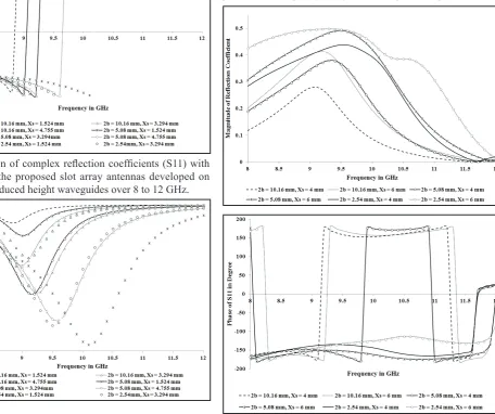
Fig. 4: Variation of complex reflection coefficients (S11) with
frequency for the proposed slot array antennas developed on
standard and reduced height waveguides over 8 to 12 GHz.
Fig. 5: Variation of complex transmission coefficients (S21) with
frequency for the proposed slot antennas developed on standard
and reduced height waveguides over 8 to 12 GHz.
The magnitude of the S – parameters of the antenna structures for
slots length = 16 mm, slot distance along the propagation direction = 23.4 mm and 22.7 mm, width = 1 mm, offset = 4 mm, - 4 mm and 6 mm, - 6mm, thickness = 1.27 mm milled on a waveguide with 2a = 22.86 mm, 2b = 10.16 mm/ 5.08 mm and 2.54 mm are plotted with frequency in figure 6 and figure 7 respectively.
Fig. 6: Variation of complex reflection coefficients (S11) with
frequency for the proposed slot antennas developed on standard
Fig. 7: Variation of complex transmission coefficients (S21) with
frequency for the proposed slot antennas developed on standard
and reduced height waveguides over 8 to 12 GHz.
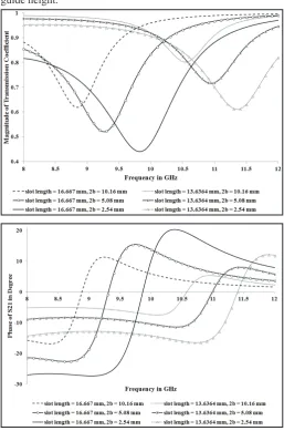
The magnitude of the S – parameters of the antenna structures
for slots length = 16.667 mm and 13.6364 mm, width = 1 mm, offset = 4.755 mm, - 4.755 mm, thickness = 1.27 mm milled on a waveguide with 2a = 22.86 mm, 2b = 10.16 mm/ 5.08 mm and 2.54 mm are plotted with frequency in figure 8 and figure 9
respectively.
Fig. 8: Variation of complex reflection coefficients (S11) with
frequency for the antenna system with different slot length and guide height.
Fig. 9: Variation of complex transmission coefficients (S21) with
frequency for the antenna system with different slot length and guide height.
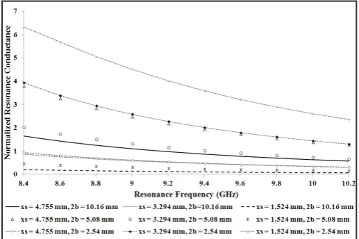
Fig. 10: Variation of normalized conductance for the proposed
slot array antennas developed on standard and reduced height
waveguides over 8 to 12 GHz.
Fig. 11: Variation of resonant length for the proposed slot array antennas developed on standard and reduced height waveguides
over 8 to 12 GHz.
IV. Conclusions
This paper presents, method of moments based analysis of reduced
height as well as of standard height broad-wall longitudinal slots antenna using Multiple Cavity Modeling Technique (MCMT). Theoretical data for reflection coefficient and transmission
coefficient have been obtained for the antenna system and also have been compared with HFSS and measured data in figure 3 to
validate the analysis. The excellent agreement obtained between them validates analysis.
The variations of the complex S-parameter with frequency for
different slot offset and guide height have been shown in figure
4 – 5. Figure 4 shows that as the slot offset increases (keeping
guide height constant) the magnitude of reflection coefficient and
resonance frequency increases. In addition if the guide height
decreases (keeping slot offset constant) the magnitude of reflection coefficient and resonance frequency increases. Figure 5 shows as the slot offset increases (keeping guide height constant) the |S21|
also decreases. Similarly if the guide height decreases (keeping
slot offset constant) the |S21| also decreases.
Figure 6 – 7 shows that the antenna network parameters depend on slot offset and guide height. Figure 6 shows that as the slot
offset increases (keeping guide height constant) the magnitude of
reflection coefficient and resonance frequency increases. However
if the guide height decreases (keeping slot offset constant) the
magnitude of reflection coefficient and resonance frequency
increases. Figure 7 shows as the slot offset increases (keeping
guide height constant) the |S21| also decreases. Similarly if the
guide height decreases (keeping slot offset constant) the |S21| also decreases and resonance frequency increases.
Figure 8-9 shows that the antenna network parameters depends both on the slot length and guide height. Figure 8 shows that if the slot length is increased, the magnitude of reflection coefficient
increases and the resonance frequency decreases (for same guide
height). Reflection coefficient and the resonance frequency also
increase with decrease in guide height for the same slot length.
Figure 9 shows that as slot length is increased |S12| decreases for
the same guide height. |S12| also decreases with the increase in
guide height if slot length is kept constant.
As evident from figure 10, the resonance conductance increase with decrease in guide height, provided slot offset is kept constant. If slot offset is increased, keeping guide height constant, resonance
conductance increases.
Finally fig. 11 reveals that the resonance slot length depends on
guide height and slot offset. If the slot offset increases (keeping guide height constant) the resonance slot length increases. Similarly if the guide height decreases (keeping slot offset constant) the resonance slot length increases.
Finally, this paper demonstrates that MCMT can also effectively incorparete the internal mutual coupling, essential for the analysis
of antenna arrays. Therefore we can conclude that MCMT can be applied for the analysis of antenna arrays.
V. Acknowledgment
The measurements were carried out in the Department of
Electronics and Electrical Communication Engineering, Indian
Institute of Technology – Kharagpur and the authors wish to express their gratitude to Prof. A. Bhattacharya of Indian Institute of
Technology, Kharagpur, for allowing us to use the lab facility.
References
[1] S. Gupta,"Electromagnetic field estimation in aperture and slot Antennas with their equivalent network representation", Phd Dissertation, Department of Electronics & Electrical Communication Engineering, I.I.T. Kharagpur, India, 1996.
[2] A. Datta, A. Chakraborty, B.N. Das,“Analysis of a strip
loaded resonant longitudinal slot in the broad wall of a
rectangular waveguide”, IEE Proceedings-h, Vol. 140, No. 2, April 1993.
[3] H. Matzner, N. Amir,“Efficient moment method solution for a longitudinal slot in a rectangular waveguide”, IEE Proc.-Microw. Antennas Propag., Vol. 153, No. 4, August 2006. [4] Yang H. Kim, Hyo J. Eom,"Mode-Matching Model for a
Longitudinally Slotted Waveguide Array”, IEEE Antenna and wireless propagation letters, Vol. 6, 2007.
[5] Yang H. Kim, Hyo J. Eom,“Radiation from Longitudinal Slots on the Narrow Wall of a Rectangular Waveguide”, IEEE Antenna and wireless propagation letters, Vol. 7, 2008. [6] Giorgio Montisci, Giuseppe Mazzarella,“Effect of the
Longitudinal Component of the Aperture Electric Field
on the Analysis of Waveguide Longitudinal Slots”, IEEE Transaction on Antenna and Propagation, Vol. 59, No. 11, November 2011.
[7] I. P. Kaminow, R. J. Stegen.,“Waveguide slot array design”, NTIS Report, AD63600, 1954.
1967.
[9] A. J. Sangstar, H. Wang,“Resonance properties of omnidirectional slot doublet in rectangular waveguide”, Electronics Letters., Vol. 29, No. 1, pp. 16 – 18, January 1993.
[10] A. J. Sangstar, H. Wang,“Moment method analysis of a horizontally polarized omnidirectional slot array antenna”, Proc. of IEE Microwave Antenna Propagation., Vol. 142, No. 1, pp. 1–6, February 1995.
[11] J. C. Coetree, J. Joubert,“Analysis procedure for arrays
of waveguide slot doublets based on the full T-network
equivalent circuit representation of radiators”, Proceedings of IEE Microwave Antenna Propagation., Vol. 147, No. 3, pp. 173 – 178, February 2000.
[12] P. Mondal, A. Chakrabarty,“Equivalent circuit representation of waveguide slot doublet”, Proceedinngs of APSYM 2006, pp. 111 - 114, December, 2006.
[13] P. Mondal, A. Chakrabarty,“Slotted waveguide antenna with two radiation nulls”, IEEE transactions on Antennas and propagation, Vol. 56, No. 9, pp. 3045 – 3049, Sepetember 2008.
[14] R. F. Harrington, Field Computation By Moment Methods, Roger E. Krieger Publishing Company, USA, pp. 5 – 7. [15] B. N. Das, G. S. Sanyal.,“Network Parameters of A Waveguide