Optimization Study on TSF Based on Dynamic
Modeling Combined with Genetic Algorithm for a
Steel Mill
Wang Li-guo
1, Li Linchun
1, Lv Linlin
1, Xu Dian-guo
11
Dept. of Electrical and Electronics Engineering, Harbin Institute of Technology, Harbin, ChinaAbstract— Considering the terrible harmonic
pollution and rapid variable reactive power due to the
furnaces of 35kV bus, the TSF(Thyristor Switched
Filters)has been studied in this paper. Due to superior
performance of TSF such as high voltage, big capacity and
fast response of compensating reactive power, it was
applied to suppress harmonic current and compensate
reactive power of secondary side of main transformer of a
steel mill of Heilongjiang Province in China. An
optimization method of TSF that combining dynamics
with GA (Genetic Algorithm) is proposed in this paper.
The work conditions of TSF were modeled and analyzed
by Thevenin and Norton theorem, respectively.
Considering the perturbation of impedance and frequency
of the 35kV power system, response of fundamental
current injected into every filter of TSF was analyzed
based on dynamics analyzing method. Expressions of
harmonic current injected into every filter of TSF were
given by character calculation. The results of numerical
analysis and measuring results show that, by TSF the
harmonic currents injected into power system accord with
Chinese national standard GB/T-14549-93 and its power
factor is increased to 0.95 from before 0.82. In fact,
proposed method can apply to suppress harmonics and
compensate reactive power of furnace of 35kV bus of the
steel mile.
Index Term— Thyristor Switched Filter; dynamics
modeling; parameter perturbation; harmonic current;
reactive power; GA (Genetic Algorithm)
I. INTRODUCTION
Comparing to Passive Power Filter (PPF), Thyristor
Switched Filters (TSF) can compensate dynamic reactive
power and prevent over compensation. Comparing to
Static Var Compensator (SVC) [1-2] and Static Var
Generator (SVG) [3], TSF has the advantages of high
voltage, fast compensating dynamic reactive power,
suppressing harmonic and eliminating voltage flicker
efficiently. Comparing to Hybrid Active Power Filter
(HAPF) [4,5], TSF has the advantage of lower cost and
better work effect. Therefore, the research on TSF has
great practical value on solving the problems of serious
harmonic pollution and dynamic compensation of
reactive power on electrical distribution network of high
voltage. It also has better effect on protecting power
system and corresponding electrical equipment [6,7].
The biggest advantage of TSF to PPF is that the
switch of PPF was substituted by thyristor of TSF. In
fact, TSF can switch tuning filter by thyristor
immediately and accurately according to require of
actual reactive power. Considering the resonance of the
reactance of power system with filter capacitor of TSF
due to the harmonic current, selecting a set of
appropriate parameters of TSF is one of the main
difficulties for designing TSF. Corresponding to the
basic coding rules Thyristor Switched Capacitor (TSC)
and PPF, TSF must be taken into consideration of both
difficulties [8]. Among performance criterion of TSF
such as stability, cost, voltage grade, filter effect,
compensation capacity, the stability must be first
considered due to the potential influence of resonance
between TSF and inductance of the power system.
Especially the perturbation of frequency and inductance
of power system must be considered in order to avoid
the resonance of TSF. In fact series and parallel
resonance between TSF and power system often decided
Manuscript received Jul. 25, 2010; revised Aug. 9, 2011
†
Corresponding Author: [email protected] Tel: +86-451-86413420, Fax: +86-451-86413420, Harbin
Institute of Tech.
*
by parameters of TSF. Fig.1 gives a resonance photo of
TSF with power system of 690V. It shows that the
thyristor and the capacitor of TSF are all burned-out due
to the resonance. Therefore, when design TSF, accurate
parameters that may be avoid resonance and ensure the
safety and stability of TSF must be considered [9-10].
Fig. 1. Resonance photo of TSF with power system
How to obtain optimization parameters of TSF
based on analyzing the performance, effect and cost is
the main study intention in this paper. A method of
optimization modeling TSF that combining dynamics
analysis with GA [11] is proposed, in order to suppress
harmonic current and compensate reactive power of the
DC furnace of a steel mill. Based on modeling
fundamental and harmonic current between power
system, DC furnace and TSF, the equations described
dynamic behavior of TSF has been derived. By the
dynamic modeling TSF the influence of perturbation of frequency and power system’s impedance on TSF has been analyzed. Moreover, in order to avoid resonance of
TSF with power system, parameters of TSF may be
optimized by GA based on optimization criterion of
stability and cost. Based on above discussing, a TSF that
consists of 3.th, 5.th, 7.th, 11.th, 13.th and high pass
filter which capacity is 6.82MVar is given. The practice
measuring data show that, the harmonic currents inject
into 35kV bus completely accord with Chinese national
standard GB/T-14549-93 and its power factor is
increased to 0.95 from 0.82. The actual measured
harmonic current of the 35kV distribution feeder verifies
the feasibility and validity of proposed method.
II. GENETIC ALGORITHM
Based on GA that was proposed by professor
Holland of Michigan state university, multi-objective
optimization of parameters of TSF was considered. It
superiority function consist of some terms discussed as
follows [11].
A. Filter effect and total harmonic distortion (THD)
The design principle of TSF is to filter the
harmonic current that feedback to the power system. By
TSF the harmonic current must be lower than Chinese
national standard GB/T-14549-93. THD of the current is
the first optimizing criterion when the multi objective
optimization method is applied to optimize the TSF. If
fundamental current and every order of harmonic current
was obtained the THD may be expressed as follows
.
3,5,7,11,13,23,25
2 25
1 1
i I I T
i hi
I (1a)
max T
TI (1b)
There, variable TI denotes the THD of studied
harmonic current. Variable I1 denotes fundamental
current. Variable Ihi (i3,5,7,11,13,23,25) denote the
harmonic current that was induced by the load of
harmonic source such as power rectifier of DC furnace,
inverter of the motor with high capacity and etc.
Variable TImax is the standard value of THD that is
allowed by Chinese national standard GB/T-14549-93.
According to optimization criterion of GA TI that
describes the distortion degree of current must be
minimized.
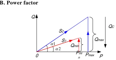
B. Power factor
0 P
Q
Pmi n
Qmax
QC
1
2
Qmin
Pmax S1
S2
Fig. 2. Vector analysis of reactive power compensation
Compensating fundamental reactive power is an
important function of TSF that including several single
tuning filters and a high passing filter. By the power
analyzer U900F the maximal and minimal reactive
power of the inductive load of a power system may be
min
Q respectively. In fig.2 variable Pmax and Pmin
correspond to maximal and minimal active power of
inductive load that satisfy following expression
1 max max
tag Q / P (2a)
2 min min
tag Q / P (2b)
Suppose TSF consists of 3.th, 5.th, 7.th, 11.th, 13.th
and high pass filter, according to multi objective
optimization method of GA, following expression must
be satisfied
max , 13 , 11 , 7 , 5 , 3
min Q Q Q
Q
h i
i
(3)
There variable Q denotes the sum of
compensating capacity of total filter that one among it
may be denoted by variableQi
i3,5,7,11,13,h
. Troubleof Eq.3 is that if above filter was switched a ccording to
reactive power only, the filter effect of TSF can’t be
considered. So filter capacity must be regarded as a
criterion of multi objective optimization of GA. Suppose
there are 3rd, 5th, 7th, 11th, 13th, 23rd and 25th harmonics
that may be denoted by I3,I5,I7,I11,I13,I23 and I25
respectively, compensating capacity of every filter may
be described as follows
3 5 7 11 13 23 25
i i i
i , , , , , ,
Q I / i I / i Q
(4)Based on above discussing a optimization strategy
of switching TSF was given which including following
two conclusions,
First, the filter with maximum compensating
capacity may be divided into several groups that with
same capacity in order to avoid overcompensation.
Second, in order to increase filter capacity of every
group, a capacitor of TSF may be instead of a group of
two series combined with two parallel connection of
capacitor.
Fig.3 Phase diagram of measured voltage and current
Fig.3 is the phase diagram of voltage and current
that measured by power analyzer. Angle of power factor
and degree of unbalancedness of three phases may be
analyzed by positive sequence, negative sequence and
zero sequence voltage and current. Fig.3 show that,
according to the multi objective optimization method of
GA, the power factor of studied power system must be
closed to 1.0, at least closed to 0.95.
C. The Lowest Cost of TSF
The cost of TSF is decided by the compensating
and filter capacity of TSF which was associated with
classification of voltage and capacity of capacitor.
Moreover, TSF may be described by a topology consists
of circuit breaker, thyristor, fuse, reactor and capacitor
and etc.. Except breaker, thyristor and fuse which rated
voltage and rated current were only calculated by above
topology model, the capacity of every reactor and
capacitor which parameters may be modified must be
considered, in order to decrease the cost of TSF.
According to multi objective optimization method
of GA, the cost of TSF was given by following
expression
h C h L h R i
i C i
LL PC P R PL PC
P
F
3,5,7,11,13
)
( (5)
TherePR,PL and PC denote the unit price of the
resistor, reactor and capacitor of TSF. Li(i3,5,7,11,13)
and Ci(i3,5,7,11,13) denote the reactor and capacitor of
ith single tuning filter respectively. Rh,LhandCh denote
the resistor, reactor and capacitor of high pass filter of
TSF. Variable
F
that denotes the total cost of TSF mustbe minimized by above multi objective optimization
method of GA.
III.STUDY BACKGROUND OF DCARC-FURNACE
In order to suppress harmonic current and
compensate reactive power, a harmonic current, power
factor, total harmonic distortion and etc. of 35kV bus of
a steel mill has been studied. The topology of
distribution power system is shown as Fig.4. Rating
capacity of main transformer 1# is 12.5MVA. The
voltage of primary side and secondary side is 35kV and
0.24kV respectively. Short-circuit impedance of main
transformer which connection type is Y/△ is 6.67%.
There is in-phase inverse parallel rectifier with rated
current 6kA in order to eliminate 5th and 7th harmonic
iA iA ’
i
35kVia id/2 ia ’
i
dT2
id/2
AC DC
furnace
T3
furnace
240V
220V
12500kV A 6.67%
12500kV A 6.67%
T1
Fig. 4. Schematic diagram of electric arc furnace
There are two DC electric arc-furnaces for rough
working and two AC arc-furnaces for precision working
in steel mill. Due to asymmetric triggering pulse of
inverse parallel rectifier there are 5th, 7th, 11th, 13th, 23rd
and 25th harmonic current in 35kV bus. Considering AC
arc-furnace with 5000kVA the 3rd harmonic current must
be analyzed.
As shown in Fig.4 primary side of transformer T1
and T2 was measured by a Power Quality Analyzer
U900F. Every harmonic current injected into 35kV
distribution feeder was shown as Tab.1. According to
Chinese national standard GB/T-14549-93 and base
short-circuit capacity of 35kV bus the harmonic
standard value was given that was shown by second row
of Tab.I.
Table I
Harmonic current injected into phase C of 35kV distribution feeder
(A)
order n harmonic
(A)
3 5 7 11 13 23 25
China
standard 18.0 18.0 13.2 8.4 7.0 4.1 3.8 95%
probability 20.3 32.0 36.6 20.5 15.2 4.5 3.9 Maximum
value 30 60 52 32 22 8.3 7.2
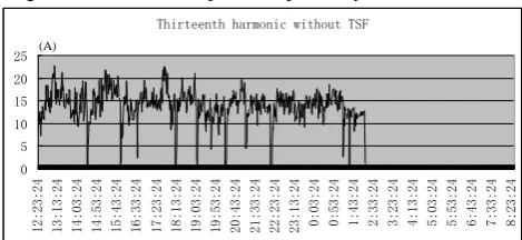
The Tab.I and Fig.5 - Fig.10 show that, the 3rd, 5th,
7th, 11th, 13th, 23rd and 25th harmonic currents were
greater than national standard of China. In particular
maximum values of 5th and 7th harmonic current are
especially terrible. Moreover, there are periodic
harmonic currents that were induced by work period of
arc furnace.
Fig.11 shows that the current THD of power system
is greater than 4% that permitted by Chinese national
standard. Fig.12 indicates that the power factor of this
power system is about 0.82.
Third harmonic without TSF
0 5 10 15 20 25 30 35
12:23:24 13:13:24 14:03:24 14:53:24 15:43:24 16:33:24 17:23:24 18:13:24 19:03:24 19:53:24 20:43:24 21:33:24 22:23:24 23:13:24 0:03:24 0:53:24 1:43:24 2:33:24 3:23:24 4:13:24 5:03:24 5:53:24 6:43:24 7:33:24 8:23:24 (A)
Fig. 5. 3rd harmonic inject into power system without TSF
Fifth harmonic without TSF
0 10 20 30 40 50 60 70
12:23:24 13:13:24 14:03:24 14:53:24 15:43:24 16:33:24 17:23:24 18:13:24 19:03:24 19:53:24 20:43:24 21:33:24 22:23:24 23:13:24 0:03:24 0:53:24 1:43:24 2:33:24 3:23:24 4:13:24 5:03:24 5:53:24 6:43:24 7:33:24 8:23:24 (A)
Fig. 6. 5th harmonic inject into power system without TSF
Seventh harmonic without TSF
0 10 20 30 40 50 60
12:23:24 13:13:24 14:03:24 14:53:24 15:43:24 16:33:24 17:23:24 18:13:24 19:03:24 19:53:24 20:43:24 21:33:24 22:23:24 23:13:24 0:03:24 0:53:24 1:43:24 2:33:24 3:23:24 4:13:24 5:03:24 5:53:24 6:43:24 7:33:24 8:23:24 (A)
Fig. 7. 7th harmonic inject into power system without TSF
Eleventh harmonic without TSF
0 5 10 15 20 25 30 35
12:23:24 13:13:24 14:03:24 14:53:24 15:43:24 16:33:24 17:23:24 18:13:24 19:03:24 19:53:24 20:43:24 21:33:24 22:23:24 23:13:24 0:03:24 0:53:24 1:43:24 2:33:24 3:23:24 4:13:24 5:03:24 5:53:24 6:43:24 7:33:24 8:23:24 (A)
Fig. 8. 11th harmonic inject into power system without TSF Thirteenth harmonic without TSF
0 5 10 15 20 25
12:23:24 13:13:24 14:03:24 14:53:24 15:43:24 16:33:24 17:23:24 18:13:24 19:03:24 19:53:24 20:43:24 21:33:24 22:23:24 23:13:24 0:03:24 0:53:24 1:43:24 2:33:24 3:23:24 4:13:24 5:03:24 5:53:24 6:43:24 7:33:24 8:23:24
(A)
0 3 5 7 11 13 23 25 0
10 20 30 40 50 60
harmonic order
h
a
rm
o
n
ic
c
u
rr
e
n
t
(
A
)
measured harmonic current by Power Analyzer
China nationalstandard value 95% probability value maximun value
Fig. 10. Harmonic current comparing with Chinese national standard
THD i
0 5 10 15 20 25
12:23:24 13:22:24 14:21:24 15:20:24 16:19:24 17:18:24 18:17:24 19:16:24 20:15:24 21:14:24 22:13:24 23:12:24 0:11:24 1:10:24 2:09:24 3:08:24 4:07:24 5:06:24 6:05:24 7:04:24 8:03:24
Fig. 11. THD of current of power system before TSF
power factor
0 0.2 0.4 0.6 0.8 1 1.2
12:23:24 13:30:24 14:37:24 15:44:24 16:51:24 17:58:24 19:05:24 20:12:24 21:19:24 22:26:24 23:33:24 0:40:24 1:47:24 2:54:24 4:01:24 5:08:24 6:15:24 7:22:24
Fig. 12. Power factor of power system before TSF
There were switchboard tripping, burn-out cable,
computer and TV was automatically turned on, lighting
flashing, fuse of consumer line blow out and etc in 35kV
bus of the steel mile which induced by terrible harmoni c
current.
Considering the high voltage, terrible harmonic
current, rapid varying reactive power and big
compensation capacity, TSF is applied to suppress
harmonic and compensate reactive power of DC furnace
of above steel mile.
IV. DYNAMIC MODELING OF TSF
Considering the effect of in-phase inverse parallel
rectifiers with asymmetrical 12 pulsetriggering signal of
DC furnace, a TSF consist of 5th, 7th, 11th and 13th single
tuning filter were presented. Third single tuning filter
and high pass filter of TSF were given also according to
actual measured harmonic current and power factor. The
topology of TSF was shown by Fig.13.
35kV
Ia
AC furnace
DC furnace
T1 T2
T3
13th
filter 11th
filter 7th
filter 5th
filter 3rd
filter
High passin
g filter
Fig. 13. The topology of TSF
3 L
3 R
3 C
5 L
5 R
5 C
7 L
7 R
7 C
11 L
11 R
11 C
13 L
13 R
13 C
h
C
h
R
h
L
f
i3 f
i5 i7f f
i11 i13f ihf
Lh
i
f d
i
s
L
u
d
L
f s
i
a) fundamental model
3
L
3
R
3
C
5
L
5
R
5
C
7
L
7
R
7
C
11
L
11
R
11
C
13
L
13
R
13
C
h
C
h
R
h
L
Lh
i
s
L
n
I
h
i3 i5h i7h i11h h
s
i
h
i13 ihh
b) harmonic model Fig. 14. Proposed model of TSF
When design the TSF, in order to obtain rated
voltage and rated current of corresponding reactor and
capacitor of TSF which were decided by fundamental
current of power system and harmonic current induced
by load, the fundamental model and harmonic model of
TSF were given and analyzed by Thevenin and Norton
theorem, respectively.
Fig.14 shows the fundamental and harmonic model
of TSF, respectively. There Ls 35.92mH and
mH 89 . 15 d
L denote the fundamental equivalent inductor
of power system and load, respectively. Variable u
denote the phase voltage of 35kV bus of steel
mine.Li(i3,5,7,11,13,h)andCi(i3,5,7,11,13,h) denote the
reactor and capacitor of TSF.
In Fig.14 a), suppose uCk(k3,5,7,11,13,h) and
) , 13 , 11 , 7 , 5 , 3
(k h
ikf denote voltage of capacitor and the
loop current of every single tuning filter and high pass
equations were given ) , 13 , 11 , 7 , 5 , 3 (
/C k h
i
uck kf k (6)
) 13 , 11 , 7 , 5 , 3 ( ) ( n L L i L u i R u i n s nf s cn nf n nf
(7)
s hf s ch Lh h
hf u Li u L i L
i [ ( )]/ (8)
) )( /
( h h hf Lh
Lh R L i i
i (9)
) /( )] (
[ s d s d
df u L i L L
i (10)
There df hf f f f f
f i i i i i i
i
3 5 7 11 13 (11)
In Eq.6 Variable
u
denote phase voltage of 35kVbus of power system that satisfied following expression
) 2 ( ) 3 / 35 (
2 cons f t
u (12)
There f denote fundamental frequency of power
system.
In fig.14 b), ikh(k3,5,7,11,13,h,s) denote the
harmonic current injected into ith filter and power system
respectively. Define following variables
s s j nfL
z 2 (13)
) 2 /( 2 2
/ h h h h h
h j nfC R j nfL R j nfL
z (14)
) 13 , 11 , 7 , 5 , 3 ( ) 2 / 1 2 (
R j nfL nfC i
zi i i i (15)
There zs , zh and zi denote reactance of power
system, high pass filter and ith single tuning filter
respectively. Variable n( n1,2,3,,23,25) denote the
order of harmonic current. Applying symbolic
computation, the harmonic current injected into power
system is express as follows
n s h s I Z Z Z Z Z Z Z Z Z Z Z i 13 11 7 5 3 13 11 7 5 3 // // // // // // // //
(16)
The harmonic injected into ith filter may be
expressed as follows
n s i s h i I Z Z Z Z Z Z Z Z Z Z Z i 13 11 5 3 13 11 5 3 // // // // // // // //
(17)
There In
n1,2,3,,23,25
denote every harmoniccurrent induced by the load, i.e. DC furnace in this
paper.
Table II
Parameters of a phase of TSF by classical algorithm
Order
harmonic(A)
3 5 7 11 13 h
R () 3.85 1.86 2.11 3.39 4.91 80.43
L (mH) 267.45 74.70 59.76 60.16 73.52 52.57
C
μF 5.00 6.00 3.72 1.46 0.85 0.33
kVar/unit 109 98.15 97.40 95.53 111.23 108
Value/phase 6 8 5 2 1 1
Tab. II and Tab. III show the parameters of TSF by
classical algorithm and GA respectively. Comparing
Tab.III with Tab. II, obtained parameters of TSF by
multi objective optimization of GA, especially
capacitors, were standardization product of China. It
denotes that the cost of TSF may be evidently decreased
by GA.
Table III
Parameters of a phase of TSF by GA
Order
harmonic(A)
3 5 7 11 13 h
R () 4.06 1.79 2.02 3.20 5.40 36.30
L (mH) 272.06 70.46 56.51 56.31 80.30 25.17
C
μF 4.58 6.36 3.82 1.27 0.76 0.25
kVar/unit 100
Value/phase 6 8 5 2 1 1
V. PERTURBATION ANALYSIS OF TSF
In order to decrease the cost of reactor and
capacitor and avoid overcompensating, its grade of
voltage and current of TSF must be considered also.
Based on above analysis the influence of surge current,
flicker of voltage or perturbation of impedance and
frequency of power system to TSF are studied in this
paper.
As shown by Eq.6-Eq.12, the differential equations
that described dynamic behaviors of TSF were derived
according to KCL (Kirchhoff’s Current Law) and KVL
(Kirchhoff’s Voltage Law). Considering perturbation of
fundamental frequency f and inductor Ls of power
system is within ±1% and ±5% respectively, the
influence of perturbation to rated current of capacitor of
TSF were analyzed by dynamic numerical iterative
method. Corresponding calculation results are illustrated
by Fig.15 to Fig.20.
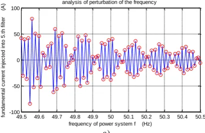
Fig.15a)-Fig.20a) show the response of
fundamental current injected into 3rd, 5th, 7th, 11th and
13th single tuning and high pass filter when the
perturbation of frequency of power system is within
(1±1%)×50Hz. It indicates that the surge current
induced by perturbation of frequency is evidently greater
than stationary fundamental current.
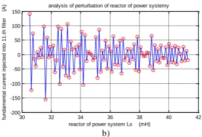
fundamental current injected into 3rd, 5th, 7th, 11th and
13th single tuning and high pass filter when the
perturbation of inductor Lsof power system is within
(1±5%)×35.93mH. It indicates that the surge current
induced by perturbation of power system is also
evidently greater than stationary fundamental current.
49.5 49.6 49.7 49.8 49.9 50 50.1 50.2 50.3 50.4 50.5 -80 -60 -40 -20 0 20 40 60 80
frequency of power system f (Hz)
fu n d a m e n ta l c u rr e n t in je c te d i n to 3 .t h f ilt e r ( A
) analysis of perturbation of the frequency
a)
30 32 34 36 38 40 42
-100 -50 0 50 100
reactor of power system Ls (mH)
fu n d a m e n ta l c u rr e n t in je c te d i n to 3 .t h f ilt e r ( A
) analysis of perturbation of reactor of power systemy
b)
Fig.15 Analysis of current injected into 3.th filter
49.5 49.6 49.7 49.8 49.9 50 50.1 50.2 50.3 50.4 50.5 -100
-50 0 50 100
frequency of power system f (Hz)
fu n d a m e n ta l c u rr e n t in je c te d i n to 5 .t h f ilt e r ( A
) analysis of perturbation of the frequency
a)
30 32 34 36 38 40 42
-300 -200 -100 0 100 200 300
reactor of power system Ls (mH)
fu n d a m e n ta l c u rr e n t in je c te d i n to 5 .t h f ilt e r ( A
) analysis of perturbation of reactor of power systemy
b)
Fig. 16. Analysis of current injected into 5.th filter
More detail data of current are illustrated by Tab.4 .
Maximum fundamental currents injected into each filter
that was described by Fig.15-fig.20 in condition of
perturbation of power system are shown by boldface of
Tab.4. It must be considered when design the rated
current of the capacitor of TSF.
49.5 49.6 49.7 49.8 49.9 50 50.1 50.2 50.3 50.4 50.5 -100
-50 0 50 100
frequency of power system f (Hz)
fu n d a m e n ta l c u rr e n t in je c te d i n to 7 .t h f ilt e r ( A
) analysis of perturbation of the frequency
a)
30 32 34 36 38 40 42
-150 -100 -50 0 50 100
reactor of power system Ls (mH)
fu n d a m e n ta l c u rr e n t in je c te d i n to 7 .t h f ilt e r ( A
) analysis of perturbation of reactor of power systemy
b)
Fig. 17. Analysis of current injected into 7.th filter
49.5 49.6 49.7 49.8 49.9 50 50.1 50.2 50.3 50.4 50.5 -150 -100 -50 0 50 100 150
frequency of power system f (Hz)
fu n d a m e n ta l c u rr e n t in je c te d i n to 1 1 .t h f ilt e r ( A
) analysis of perturbation of the frequency
30 32 34 36 38 40 42 -200 -150 -100 -50 0 50 100 150
reactor of power system Ls (mH)
fu n d a m e n ta l c u rr e n t in je c te d i n to 1 1 .t h f ilt e r ( A
) analysis of perturbation of reactor of power systemy
b)
Fig. 18. Analysis of current injected into 11.th filter
In fact, the rated current of a capacitor is decided
by fundamental and harmonic current injected into the
capacitor.
For example, according to Tab.1 and Tab.4 the
current injected into 5th single tuning filter are satisfy
following expressions A 830 . 87 2 5 2 max 5 max
5 i f ih
i (18a)
A 598 . 78 max 5 f
i (18b)
A 60 5 h
i (18c)
There, if5max and ih5 denote the maximum
fundamental and harmonic current injected into 5th
single tuning filter respectively.
49.5 49.6 49.7 49.8 49.9 50 50.1 50.2 50.3 50.4 50.5 -60 -40 -20 0 20 40 60 80
frequency of power system f (Hz)
fu n d a m e n ta l c u rr e n t in je c te d i n to 1 3 .t h f ilt e r ( A
) analysis of perturbation of the frequency
a)
30 32 34 36 38 40 42
-100 -50 0 50 100
reactor of power system Ls (mH)
fu n d a m e n ta l c u rr e n t in je c te d i n to 1 3 .t h f ilt e r ( A
) analysis of perturbation of reactor of power systemy
b)
Fig. 19. Analysis of current injected into 13.th filter
a)
b)
Fig. 20. Analysis of current injected into high pass filter Table IV
Current injected into each filter in condition of perturbation of power system
current
filter
fundamental Current
(A)
frequency f perturbation
(A)
Ls perturbation
(A)
3.th 29.398 72.153 67.155
5.th 39.198 78.598 159.153 7.th 24.499 82.746 27.004 11.th 9.799 105.855 42.804
13.th 4.900 74.701 28.426 high pass 4.900 28.401 15.431
Above principle of selecting perturbation current
accord with multi objective optimization method and
transient response of TSF that induced by perturbation
of parameters of power system. Maximum rated current
injected into each filter of TSF are shown by Tab. V.
Table V
Maximum rated current of each filter of TSF (A)
filter
current
3rd 5th 7th 11th 13th high pass
Fundamental
f
i 72.15 78.60 82.75 105.86 74.70 28.40
Harmonic ih 30 60 52 32 22 15.50
2 2
max h
f i
i 78.14 98.88 110.60 43.91 77.87 32.35
Rated current 60.12 76.06 75.18 85.07 59.90 24.89
(A)
30 32 34 36 38 40 42
-60 -40 -20 0 20 40
reactor of power system Ls (mH)
fu n d a m e n ta l c u rr e n t in je c te d i n to r e a c to r o f h .t h f ilt e r ( A )
analysis of perturbation of reactor of power systemy (A)
49.5 49.6 49.7 49.8 49.9 50 50.1 50.2 50.3 50.4 50.5 -30 -20 -10 0 10 20 30
frequency of power system f (Hz)
fu n d a m e n ta l c u rr e n t in je c te d i n to r e a c to r o f h .t h f ilt e r ( A )
Considering the operating current of a capacitor is
usually 1.3 times larger than rated current, the rated
current of a capacitor of each filter are shown by fifth
row of Tab.5. The question is that, rated current of 5th
filter is 39.198A which is 1.94 times less than maximum
current injected into this filter. A topology of two groups
including 16 capacitors first connected in parallel then
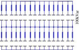
they are connected in series each other is proposed.
Above topology is illustrated by Fig.21.
1
0
0
k
V
ar
Fig. 21. Topology of capacitors of 5.th single tuning filter
By fig.21 that consists of 32 capacitors which
capacity of every capacitor is 100kVar, the actual rated
current of capacitor of 5th single tuning filter was
described by following expression
5actual 39 198 2 78 396A 76 06A
i . . . (19)
It indicates that proposed topology can bear
maximum current injected into 5th single tuning filter.
VI. FAULT ANALYSES OF TSF
A unit of 5th single tuning filter consists of 4
capacitors connected in parallel and series is shown by
Fig.22. There are total 8 same units in Fig.21.
C51 C53
C52 C54
51 i
53 i U
10
0k
V
a
r
52
i i54
fuse53 fuse51
fuse54 fuse52
C51 C53
C52 C54
51
i i53
U
10
0k
V
a
r
52
i i54
fuse53 fuse51
fuse54 fuse52
a) work state b) fault state
Fig. 22. Topology of a unit of 5.th filter
Suppose I denote the total current injected into this
unit, in work state it satisfies following expression
51// 53 52// 52
/2 5/2 5453 52
51 i i i U C C C C U C
i
(20)
In Eq.20,
5 54 53 52
51 C C C C
C (21)
In Eq.20 variablei51,i52,i53 and i54 denote the
current injected into capacitors that marked by C51, C52,
C53 and C54 respectively. Fig.22 b) illustrate the fault
state of capacitor that induced by surge current, flicker
of voltage or perturbation of impedance and frequency
of power system.
For example, if the capacitor C51 burn-out,
following expression was satisfied
53 52// 54
2 5/3 5452
53 i i U C C C U C
i (22a)
3 / 5 54
52 i U C
i (22b)
Comparing Eq.20 to Eq.22a show that current
injected into capacitor C53 in fault state is 1.333 timers
greater than that one in work state, it must be considered
when designing a TSF.
Supposing the resonance point of the 5th tuning
filter in work state is n50 that satisfy
85 . 4 2
0 . 1
5 5
50
C L n
(23)
There L5 denote the reactor of 5.th filter.
2 5.943 3
/ 2 2
0 . 1
50 5
5
50
n
C L n
(24)
It indicates that resonance point of 5th tuning filter
in fault state is 1.225 times greater than that one in work
state. Eq.24 implies that the 6th harmonic current will
inject into the 5.th tuning filter when the fault occur.
34 35.17 35.92 36.68 38
-460 -450 -440 -430 -420 -410
inductance of power system Ls (mH) analysis of perturbation of inductance of power
system
i3
+
i5
+
i7
+
i1
1+
i1
3+
ih
(
A
)
stability area period response instability area
chaos
instability area chaos
bifurcation point
Fig. 23. Analysis of perturbation of inductance of power system
Fig.23 indicate that when the perturbation of
inductance occur, the chaos of vector sum of
current
i3i5i7i11i13i23i25
will appear in conditionof inductance Ls35.17mH orLs36.68mH . Especially
there are bifurcations at Ls35.17mH or Ls36.68mH .
There is period response of
i3i5i7i11i13i23i25
are the main reasons that influence the stability of
response of TSF.
The instability of TSF, i.e. the resonance induced
by perturbation of parameters of power system must be
avoided. Above discussing may give a reference to
designing the parameters of TSF.
VII.EFFECT ANALYSIS OF TSF
In order to predict the effect of TSF the characters
calculation method was applied to modeling and
simulating the TSF.
3 5 7 11 13 23 25
0 10 20 30 40 50 60
harmonic oeder n
h
a
rm
o
n
ic
c
u
rr
e
n
t
(
A
)
China standard
actual current harmonic current harmonic current by TSF
Fig. 24. Harmonic current injected into power system
Obtained detail data was shown by Fig.24 where
the symbol “△” denote the standard value of harmonic
current accord with national standard GB/T-14549-93 of
China. Symbol “o” denotes actual harmonic current
injected into the power system, symbol “*”denotes
harmonic current by TSF.
Fig.24 indicates that the harmonic current injected
into power system by TSF was evidently lower than
national standard GB/T-14549-93. As a matter of fact,
the effect of TSF may be influenced by the many
complex elements of power system such as perturbation
of frequency and inductance, load variation and etc..
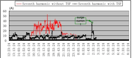
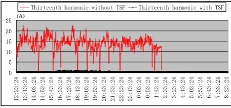
Fig.25-Fig.29 illustrates the harmonic current
injected into second line of 35kV bus by TSF which data
are measured by U900F at one time. There “+” and red
line denote the ith harmonic current injected into power
system by TSF and not respectively.
0 5 10 15 20 25 30 35
12:23:24 13:13:24 14:03:24 14:53:24 15:43:24 16:33:24 17:23:24 18:13:24 19:03:24 19:53:24 20:43:24 21:33:24 22:23:24 23:13:24 0:03:24 0:53:24 1:43:24 2:33:24 3:23:24 4:13:24 5:03:24 5:53:24 6:43:24 7:33:24 8:23:24
Third harmonic without TSF Third harmonic with TSF
(A)
Fig. 25. 3.th harmonic inject into power system by TSF
0 10 20 30 40 50 60 70
12:23:24 13:13:24 14:03:24 14:53:24 15:43:24 16:33:24 17:23:24 18:13:24 19:03:24 19:53:24 20:43:24 21:33:24 22:23:24 23:13:24 0:03:24 0:53:24 1:43:24 2:33:24 3:23:24 4:13:24 5:03:24 5:53:24 6:43:24 7:33:24 8:23:24
Fifth harmonic without TSF Fifth harmonic with TSF
(A)
surge curren t
Fig. 26. 5.th harmonic inject into power system by TSF
It indicates that the 3rd, 5th, 7th, 11th and 13th
harmonic current injected into second line of 35kV bus
by TSF are evidently less than that one when TSF wasn’t
applied.
An especially conditions were shown by Fig.26 and
Fig.27 there were some 5th or 7th harmonic current
wasn’t eliminated. For example, between 19:03:24 and
19:53:24 of Fig.26, there was a peak value of 5th
harmonic current that reached to 32A which overrated
national standard GB/T-14549-93 of China. This
problem for surges current that induced by switching
dynamic filter of TSF may solved by taking an ulterior
optimizing control stratagem of crossing zero of voltage.
0 10 20 30 40 50 60
12:23:24 13:13:24 14:03:24 14:53:24 15:43:24 16:33:24 17:23:24 18:13:24 19:03:24 19:53:24 20:43:24 21:33:24 22:23:24 23:13:24 0:03:24 0:53:24 1:43:24 2:33:24 3:23:24 4:13:24 5:03:24 5:53:24 6:43:24 7:33:24 8:23:24
Seventh harmonic without TSF Seventh harmonic with TSF
(A)
surge curren t
0 5 10 15 20 25 30 35
12:23:24 13:13:24 14:03:24 14:53:24 15:43:24 16:33:24 17:23:24 18:13:24 19:03:24 19:53:24 20:43:24 21:33:24 22:23:24 23:13:24 0:03:24 0:53:24 1:43:24 2:33:24 3:23:24 4:13:24 5:03:24 5:53:24 6:43:24 7:33:24 8:23:24
Eleventh harmonic without TSF Eleventh harmonic with TSF
(A)
Fig. 28. 11.th harmonic inject into power system by TSF
0 5 10 15 20 25
12:23:24 13:13:24 14:03:24 14:53:24 15:43:24 16:33:24 17:23:24 18:13:24 19:03:24 19:53:24 20:43:24 21:33:24 22:23:24 23:13:24 0:03:24 0:53:24 1:43:24 2:33:24 3:23:24 4:13:24 5:03:24 5:53:24 6:43:24 7:33:24 8:23:24
Thirteenth harmonic without TSF Thirteenth harmonic with TSF
(A)
Fig. 29. 13.th harmonic inject into power system by TSF
power factor
0 0.2 0.4 0.6 0.8 1 1.2
12:23:24 13:23:24 14:23:24 15:23:24 16:23:24 17:23:24 18:23:24 19:23:24 20:23:24 21:23:24 22:23:24 23:23:24 0:23:24 1:23:24 2:23:24 3:23:24 4:23:24 5:23:24 6:23:24 7:23:24 8:23:24
Fig. 30. Power factor of power system by TSF
THD i
0 2 4 6 8 10
12:23:24 13:22:24 14:21:24 15:20:24 16:19:24 17:18:24 18:17:24 19:16:24 20:15:24 21:14:24 22:13:24 23:12:24 0:11:24 1:10:24 2:09:24 3:08:24 4:07:24 5:06:24 6:05:24 7:04:24 8:03:24
Fig. 31. THD of power system by TSF
Comparing Fig.30 with Fig.12 show that, the power
factor of 35kV bus increases from 0.82 to 0.95 by TSF.
There isn’t any overcompensation of reactive power in
Fig.30.
Comparing Fig.31 with Fig.11 show that, the THD
of current of 35kV bus decreases from about 20% to
7.8%. It indicates that the harmonic current injected into
the power system was evidently suppressed.
VIII. CONCLUSIONS
In this paper the TSF was applied to suppressing
harmonic current and compensating reactive power of
the furnaces of a steel mile of China. In order to
decrease the cost of TSF the optimization method of GA
was applied to normalizing the parameters of TSF.
Based on Thevenin and Norton theorem a dynamic
model of TSF in condition of fundamental and harmonic
current that described the behavior of TSF was given
respectively.
Combining the dynamic modeling method with
KCL and KVL, the perturbation of impedance and
frequency of the 35kV power system was analyzed.
Expressions of harmonic current injected into every
filter of TSF were derived by character calculation.
Based on presented method the maximum rated current
of the capacitors and reactors of TSF may be decided.
The results of simulation model and measure
practice show that, the harmonic currents injected into
power system and power factor accord with national
standard GB/T-14549-93 of China. Except the analysis
of this paper, the proposed method may used to analyze
other similar system, such as suppress drop off voltage
and harmonic distortion of wind power system when it
was connected with the power system.
ACKNOWLEDGMENT
The authors would like to thank the support from “National Natural Science Foundation (50877016, 50877017)”.
REFERENCES
[1] Sameh K.M. Kodsi, Claudio A. Canizares, Mehrdad Kazerani, “Reactive current control through SVC for load power factor correction,” Electric Power Systems Research, vol.76, pp.701-708, 2006.
[2] Fan Ruixiang, Li Zheng, Zhao Gang, Sun Min, “The Design of Relocatable SVC and Its Application in Jiangxi Power Grid,” Automation of Electric Power System, vol.32, no.14, pp. 91-95, 2008.
[3] Shukla A, Ghosh A, Joshi A, “State Feedback Control of Multilevel Inverters for DSTATCOM Applications,” IEEE Trans. on Power Delivery, vol.22, no.4, pp. 2409-2418, 2007.
[4] Bor-Ren Lin, Bor-Ren Yang and Hui-Ru Tsai, “Analysis and Operation of Hybrid Active Filter for Harmonic Elimination,” Electric Power Systems Research, vol.62, pp.191-200, 2002.
[5] Murat Kale, Engin Ozdemir, “Harmonic and reactive power compensation with shunt active power filter under non-ideal mains voltage,” Electric Power Systems Research, vol.74, pp.363-370, 2005.
Systems Research, vol.53, pp.133-140, 2001.
[7] Yong Zhao, Hongying Deng, Jianhua Li, Daozhi Xia, “Optimal planning of harmonic filters on distribution systems by chance constrained programming,” Electric Power Systems Research, vol.68, pp.149-156, 2004. [8] Wang Li-guo, Xia Yu, Ren Xiang, Xu Dian-guo, Xu
Zhuang, “Passive Control on the Negative Effect of Thyristor Switched Capacitor (I),” Asia-Pacific Power and Energy Engineering Conference, number: 5748810. [9] A.Wolf and M.Thamodharan, “Reactive Power Reduction
in Three-Phase Electric Arc Furnace,” IEEE Transactions on Industrial Electronics, vol. 47, no. 4, pp. 729-733, 2000. [10] Rohani R, Porkar B, “Improved EHV Line Switching Surge
Control via Controlled Switching Technique,” IEEE PEDES,vol.1, no.1, pp.1-4, 2010.
[11] Gao JQ; He GX; Wang YS, “A new parallel genetic algorithm for solving multiobjective scheduling problems subjected to special process constraint,” International Journal of Advanced Manufacturing Technology, vol.43, no.1, pp. 151-156, 2009.
Liguo Wang was born in Heilongjiang
Province, China, in 1972. He received his Ph.D.
in Electrical Engineering from the Harbin Institute of Technology, Harbin, China, in 2002.
Since 2003, he has been with the Department of Electrical and Electronics Engineering, Harbin Institute of Technology, where he is currently an Associate Professor. His current research interests
include harmonic suppression and reactive power compensation of power system, parameter identification in ac machines, and nonlinear