JETIR1404009 Journal of Emerging Technologies and Innovative Research (JETIR) www.jetir.org 248
Novel Image Compression using Modified DCT
Telagarapu Prabhakar
Department Electronics & Communication Engineering, GMR Institute of Technology, Rajam, Andhra Pradesh, India.
Abstract—Image compression is a widely addressed research area. Many compression standards are in place. But still
here there is a scope for high compression with quality reconstruction. In order to reduce the volume of multimedia data over wireless channels, data compression techniques are widely used. Discrete Cosine Transform (DCT) is one of the major compressions Scheme. Dynamic bit-width adaptation scheme in Discrete Cosine Transform (DCT) is proposed as an efficient compression technique. Experimentation has been carried out to perform image compression based on DCT, Discrete Wavelet Transform (DWT) and Dynamic bit-width adaptation scheme in discrete cosine transform. The performance evaluation of the three methods is done based on PSNR which proves that Dynamic bit-width adaptation scheme in DCT is superior.
Index Terms—Dynamic bit-width adaptation scheme in DCT, Discrete Wavelet Transform (DWT), Discrete Cosine
Transform (DCT), Performance Evaluation of Image Compression Methods, PSNR.
________________________________________________________________________________________________________
I.INTRODUCTION
As multimedia applications become more popular, there is a greater demand for the efficient representation of many different types of data. To accommodate the increasing use of multimedia in network environments, the amount of data transmitted must be minimized. Uncompressed multimedia (graphics, audio and video) data requires considerable storage capacity. Compressing multimedia data such as an image is significantly different than compressing raw binary data. Of course, general purpose compression programs can be used to compress images, but the result is less than optimal [1-3]. For still image compression, the `Joint Photographic Experts Group' or JPEG standard has been established by ISO (International Standards Organization) and IEC (International Electro-Technical Commission). The performance of these coders generally degrades at low bit-rates mainly because of the underlying block-based Discrete Cosine Transform (DCT) scheme. More recently, the wavelet transform has emerged as a cutting edge technology, within the field of image compression. Wavelet-based coding provides substantial improvements in picture quality at higher compression ratios. Dynamic bit-width adaptation is suitable for DCT applications to efficiently trade off image quality for lower energy of computation [2-6]. Depending on the sensitivities of 64 DCT coefficients, operands of different bit-widths are used to reduce the computational complexity. To select appropriate operand bit-widths that give rise to considerable power savings with minimum image quality degradation, propose an efficient bit-width selection algorithm. The modification is mainly focused on both Shift Row Transformations. In the Shift Row Transformation, if the value in the first row and first column is even, the first and fourth rows are unchanged and each bytes in the second and third rows of the state are cyclically shifted right over different number, else the first and third rows are unchanged and each byte of the second and fourth rows of the state are cyclically shifted left over different number of bytes. This modification allows for greater security and increased performance[7-10].
II.TRANSFORMSUSED
In this section, the mathematical representations of Discrete Cosine Transform and Discrete Wavelet Transform are explored.
A. 2-D DCT Operation in Separable Form
Implementation of DCT practically is done by using Separability property of DCT. First of let us see what is separability [2].
The 2D-DCT transform equation can be expressed as,
( ) ( )
1 1
0 0
(2 1) (2 1)
( , ) [ ] cos ( , )cos
2
]
2[
[
]
N N
x y
u v x u y
c u v X K f x y
N N α α π π − − = = + + = =
--- (1) For u, v =0, 1, 2, N −1.
This property, known as separability, has the principle advantage that C(u, v) can be computed in two steps by successive 1-D operations on rows and columns of an image. The arguments presented can be identically applied for the inverse DCT computation.
The 1-D discrete cosine transform (DCT) is defined as
( )
( )
( )
(
)
(
2
)
2
1
2
cos
1 0−
+
⋅
=
− = N xN
u
x
x
f
u
u
C
α
π
JETIR1404009 Journal of Emerging Technologies and Innovative Research (JETIR) www.jetir.org 249
( )
(
3
)
1
,...,
2
,
1
for
2
0
for
1
−
−
=
=
=
N
u
N
u
N
u
α
The output of the 2-D DCT, which is the 8x 8 block of 64 DCT coefficients, are quantized to eliminate less significant components. Each of the 64 DCT coefficients is divided by an integer number in the quantization table and rounded off.However, considering that high frequency DCT coefficients become negligibly small after quantization, expect that overall image quality would not be affected significantly even if decrease the bit-width of arithmetic units used for computation of high frequency coefficients [14].
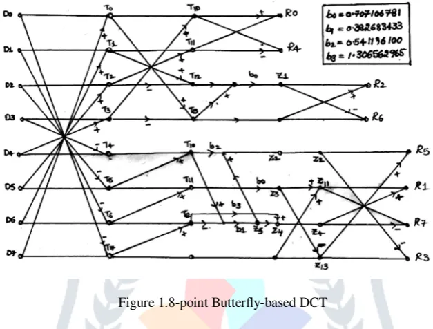
Figure 1.8-point Butterfly-based DCT
8-point Butterfly-based DCT/IDCT shown in Fig.2 is used to save the computational complexity efficiently. By using smaller bit-widths for calculating high frequency components, to achieve significant improvement in computation power at the expense of slight degradation in image quality. However, it is important to judiciously reduce the operand bit-widths for each DCT coefficient to minimize power consumption.
B. Discrete Wavelet Transform
In Sub band coding [16], signals are decomposed into a number of sub band signals using an analysis filter bank, and the adaptive filtering is performed on each sub band. The result in each sub band is combined into an output using a synthesis filter bank. If the sub band signals are band limited to frequency ranges much smaller than that of the original input signal they can be down sampled before processing. Because of the lower sampling rate, the processing of the down sampled signals can be carried out more efficiently. After processing, these signals are up sampled before being combined by the synthesis bank into a higher rate signal. The combined structure employed is called a quadrature mirror filter (QMF) bank. If the down sampling and up sampling factors are equal to or greater than the number of bands of the filter bank, then the output can be made to retain some or all of the characteristics of the input by properly choosing the filters in the structure. In the case of equality, the filter bank is said to be a critically sampled filter bank. The most common application of this scheme is in the efficient coding of a signal [11-12].
JETIR1404009 Journal of Emerging Technologies and Innovative Research (JETIR) www.jetir.org 250 Figure 3 Schematic diagram of 2D wavelet transform
III.BIT-WIDTHSELECTIONALGORITHMINDCT
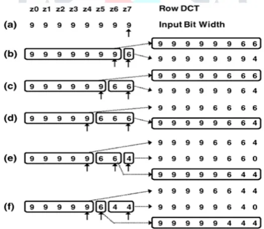
The set of permissible bit-width of adders to 12, 9, 6, 4, and 0 bits, where 0 bit means that no calculation is performed on the input. A point worth noting is that may be able to achieve more power savings by increasing the set of permissible adder sizes, but it would significantly increase the design space to explore as well as the complexity of hardware implementation. Fig. 3 illustrates the procedure to select a DCT operand whose bit-width is reduced. For the sake of simplicity, use 1-D DCT as an example, but the implemented algorithm deals with the bit widths of row DCT and column DCT operands simultaneously. In the Fig.5, Z0, Z7 are the outputs of 1-D DCT, where Z7 stands for the highest frequency componentand Z0 for the lowest frequency component. Initially, all the input bit-widths are 9 bits (the maximum input bit-width of row DCT), as shown in Fig. 5(a). First, try to reduce the bit-width for Z7 which is the least sensitive high frequency component. Decrease the bit-width for Z7 from 9 to 6 bits and check the image quality. If it still satisfies given image constraint, this change is confirmed [13].
Figure 4 Example of bit-width selection algorithm applied to row DCT.
In Fig. 5(b), have two groups, one with 9-bit width operands (Z0 - Z6) and the other one with 6-bit width operand (Z7). In this case, have two candidates for bit-width reduction: One is Z6, which is least sensitive to image quality among the first group, and the other is Z7. After calculating the PSNR of the two cases (Z7 = 6, Z6 = 6 and Z7 = 4, Z6 = 9), select the case which gives larger PSNR and reduce the bit width of the associated operand. Only one candidate is selected at a time and the bit-width of the selected candidate is reduced by one level (from 9 to 6 bits, from 6 to 4 bits, and so on). Figs. 5(e) and 5(f) show examples of three-candidate cases. The one with the largest PSNR among the three cases is chosen and the operand bit-width associated with that case is decreased. The algorithm continues until no candidate can satisfy the image quality constraint.
IV.EXPERIMENTALRESULTS
JETIR1404009 Journal of Emerging Technologies and Innovative Research (JETIR) www.jetir.org 251
Case I Case II Case III
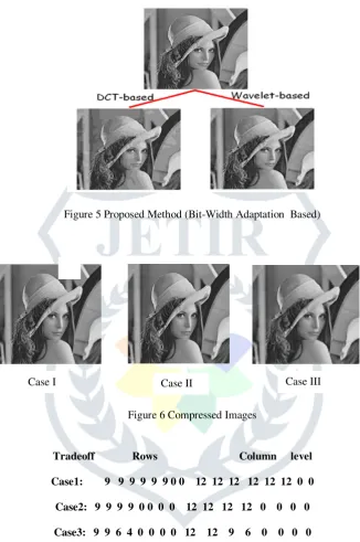
Processor with 2GB RAM. The performance of the three methods is evaluated by calculating PSNR. The original Image(Lena) and the compressed images based on the three techniques are shown in Fig.6.
In normal operation, 9-bit inputs and 12-bit inputs are used for row DCT and column DCT, respectively. As we go to the higher trade-off levels (sacrificing image quality in favor oflower power), the input bit-width for calculating both rowand column DCT is reduced, starting from the less sensitive
Figure 5 Proposed Method (Bit-Width Adaptation Based)
Figure 6 Compressed Images
Tradeoff Rows Column level
Case1: 9 9 9 9 9 9 0 0 12 12 12 12 12 12 0 0
Case2: 9 9 9 9 0 0 0 0 12 12 12 12 0 0 0 0
Case3: 9 9 6 4 0 0 0 0 12 12 9 6 0 0 0 0
Figure 6 Input operand bit-width in 2-D DCT operation for three different trade-off levels
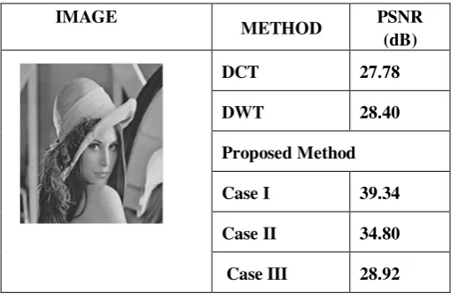
JETIR1404009 Journal of Emerging Technologies and Innovative Research (JETIR) www.jetir.org 252 Table 1The PSNR values of the three methods
IMAGE
METHOD PSNR
(dB)
DCT 27.78
DWT 28.40
Proposed Method
Case I 39.34
Case II 34.80
Case III 28.92
V.CONCLUSION
In this paper, the Dynamic bit-width adaptation is used in the DCT compression technique, where operand bit-widths are changed according to image quality and/or power consumptionrequirements. So for designing a better image compression system bit-width adaptation can be used in order to meet the power level requirements.
REFERENCES
[1] Jongsun Park, Member, IEEE, Jung Hwan Choi, Student Member, IEEE, and Kaushik Roy, Fellow, IEEE, “Dynamic Bit- Width Adaptation in DCT “, IEEE transactions on very large scale integration (vlsi) systems, vol. 18, no. 5, may 2010. [2] N. Ahmed, T. Natarajan, and K. R. Rao, “Discrete cosine transform,” IEEE Trans. Computer, vol. C-23, no. 1, pp. 90–93,
Jan. 1974.
[3] Sinha, A. Wang, and A. Chandrakasan, “Energy scalable system design,” IEEE Trans. Very Large Scale Integr. (VLSI) Syst., vol. 10, no. 2, pp. 135–145, Apr. 2002.
[4] J. Park and K. Roy, “A low power reconfigurable DCT architecture to trade off image quality for computational complexity,” in Proc. Int. Conf. Acoust., Speech Signal Process. (ICASSP), May 2004, vol. 5, pp. 17–20.
[5] J. Park, J. Choi, and K. Roy, “Dynamic bit-width adaptation in DCT: image quality versus computation energy trade-off,” in Proc. Des., Autom., Test Eur. (DATE), Mar. 2006, pp. 520–521.
[6] Telagarapu, Prabhakar, et al. "Image compression using DCT and wavelet transformations." International Journal of Signal Processing, Image Processing and Pattern Recognition 4.3 (2011): 61-74.
[7] T. Xanthopoulos and A. Chandrakasan, “A low-power DCT core using adaptive bit width and arithmetic activity exploring signal correlations and quantization,” IEEE J. Solid-State Circuits, vol. 35, no. 5, pp. 740–750, May 2000. [8] Shujun Li, Guanrong Chen and Xuan Zheng, "Chaos-based encryption for digital images and videos," chapter 4 in
Multimedia Security Handbook, February 2004.
[9] H. Cheng, L. Xiaobo, Partial encryption of compressed images and videos. IEEE Trans. Signal Process. 48 (8), 2439– 2451, 2000.
[10]Digital Compression and Coding of Continuous-Tone Still Images, ITU-T Recommendation T.81, Sep. 1992.
[11]J. M. Rabaey, A. Chandrakasan, and B. Nikolic, Digital Integrated Circuits, 2nd ed. Englewood Cliffs, NJ: Prentice– Hall, 2003.
[12]Synopsys Inc., San Jose, CA, “Nanosim reference guide,” Jun. 2001.
[13]Telagarapu, Prabhakar, BirendraBiswal, and VijayaSanthiGuntuku."Security of image in multimedia applications." Energy, Automation, and Signal (ICEAS), 2011 International Conference on. IEEE, 2011.