Coreless Transformer Technology
Vasantkumar Upadhye
Assistant Professor,
Department of Electrical and Electronics Engineering
Angadi Institute of Technology and Management, Belagavi, Karnataka, India
Anushri Nair
Department of Electronics and Communication Engineering Angadi Institute of Technology and Management, Belagavi, Karnataka, India
Abstract- Magnetic cores have been used in transformers in most of power converters for a long time. Coreless PCB transformers have the advantages of low costs, very high power density, no limitation due to magnetic cores, no magnetic loss and ease of manufacturing. They have the potential to be developed in microcircuits. Coreless printed transformers have great potential in applications in which stringent height and space requirements have to be met. This paper contains introduction, discussion of problems in high frequency magnetics, brief outlook on the coreless transformer technology, design and equivalent circuit model of the coreless transformer, types of the structures available, advantages and its applications. The high frequency capability, high reliability and the low profile structure make these transformers a viable and attractive option for reliable mega hertz switching converters and micro circuits.
Keywords – High frequency magnetics, Coreless Transformer Technology, BCB, Planar transformer, Stacked transformer, Segmented and Interleaved stacked Transformer.
I.INTRODUCTION
In this modern era, where we can find miniaturized electronic circuits, planar technology plays a prominent role because of their small size and reduced weight with high power density. The demand for power supplies in modern electronic equipment is ever increasing as it is essential for all electronic systems. The need for compactness of the power converter has led to the increase in operating frequency and the use of planar magnetics. Additionally, the efficiency of the switch mode power supplies can be increased by using higher operating frequencies.[2]
Some of the applications demand electrical isolation and multiple outputs, transformers have become the irreplaceable components in modern power supplies. The switching frequencies of isolated power supplies are limited to few hundreds of kHz because of the increased hysteresis and eddy current losses of core based transformers and the switching losses of the Power MOSFET at higher operating frequencies. The other major problems involved in high frequency magnetics are leakage inductance, skin and proximity effects and unbalanced magnetic flux distribution, which generate localized hot spots and reduce the coupling coefficient.[1]
II.CORELESSTRANSFORMERTECHNOLOGY
2.1 Problems In High Frequency Magnetics –
The problem with miniaturization of power conversion circuits such as AC to DC switch mode power supplies and DC to DC converters is the construction of the inductors and transformers. In general, the increased switching frequency leads to a reduction in size of the magnetic components but at frequencies in MHz region several other issues arise. The core materials commonly used in 20-500 KHz region have increased hysteresis and eddy current loss at the higher frequencies. Also the problems due to the skin effect and proximity effect get added up at high frequency. Commonly used magnetic core-based transformers for isolated gate drive circuits or low power converters require a manual winding process, which not only increases the labor cost, but also prohibits full automation of the circuits in their manufacture. This is the motivation to use coreless transformers (CLT).
Traditionally, magnetic cores are used in transformers for providing good magnetic paths for the energy to transfer from the primary to the secondary, or vice versa. Because of the relatively high manufacturing cost of manually wound transformers and inductors, recent research has focused on making transformer and/or inductor windings on printed circuit boards (PCB’s). Planar transformers provide a good solution for high-frequency switching-mode power supplies (SMPS). Since this class of transformers has advantages that improve the SMPS performance, their use has grown in recent years. Some of the high frequency parasitics can be drastically reduced due to their planar geometry and the proximity of the windings. Leakage inductance can be drastically reduced in these transformers due to the 4 proximity of the windings. The AC resistance is also reduced due to the high perimeter or area ratio of the conductors.[2]
Coreless PCB transformers do not have the limitations associated with magnetic cores, such as the frequency limitation, magnetic saturation and core losses. In addition, they eliminate the manual winding process and its associated problems, including labor cost, reliability problems and difficulties in ensuring transformer quality in the manufacturing process. The parameters of the printed windings can be precisely controlled in modern PCB technology. Because of the drastic reduction in the vertical dimension, coreless PCB transformers can achieve high power density and are suitable for applications in which stringent height requirements for the circuits have to be met.[3]
For some applications especially or when full integration is not practical, it could be advantageous to have a discrete integrated coreless component. More, recent applications involve high operating temperatures (the ambient is over 200°C), where the driver, closely placed to the power core, is stressed at the same time by high voltages and high temperatures.[4]
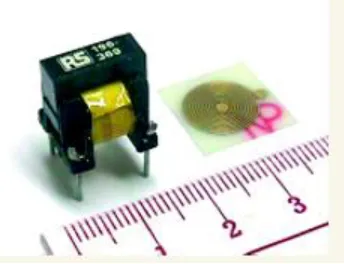
Figure 2.1: Photograph of a coreless PCB transformer (right) and a core-based transformer (left)
2.2. Coreless Transformer Technology –
metal, see figure 2.2. The primary winding and the secondary winding are etched on the same metal level, while the second metal level is used to "bring back" the extremum of the coil from the center of the device to the side of the chip. For some applications it is necessary to have the contact pads at the corner of the chip, for improved insulation in the package for example. This implementation is called "single layer" transformer and is noted "TRS". It was chosen over a double layer structure because the parasitic capacitance is less. In the double layer structure, an additional capacitance is introduced by the coils facing each other to form a planar capacitor.
.
Table (a): Electrical and Thermal Properties of Photo-BCB (CYCLOTENE 4000 resin series)
Figure 2.2: Technological description of a single layer transformer.
2.3CORELESSTRANSFORMERDESIGN-
peak current for a fixed voltage and frequency. Thirdly, the parasitic capacitance is estimated. The input parameters are: inner diameter din, track width w, track spacing s, number of turns n. Three constraints are taken into account: mechanical dimensions < 3mm, transceiver drive current < 25mA and parasitic capacitance between primary and secondary coils < 15pF. Many solutions, ranging from 30 turns to 60 turns, have been built with different layout options in a first explorative wafer run. The optimal solution is presented, a single layer 30 turn transformer with maximized winding density: minimal allowed track spacing and width. The parasitic capacitance between the primary winding and the secondary winding can be evaluated by considering single layer structure of the transformer. Two wires, primary and secondary are wound side by side producing a wire-to-wire capacitance.[4]
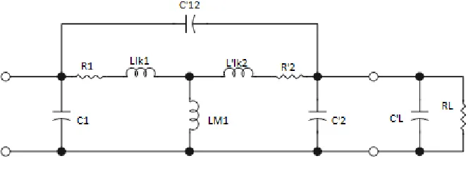
The equivalent circuit of a coreless PCB transformer is shown in Fig. 2.2, where,
R1 is the primary winding resistance,
R'2 is the secondary winding resistance referred to the primary,
RL is the resistive load,
Llk1 is the primary leakage inductance,
L'lk2 is the secondary leakage inductance referred to the primary,
LM1 is the primary mutual inductance,
C1 is the primary winding capacitance,
C'2 is the capacitance in the secondary winding referred to the primary,
C12 is the capacitance between primary and secondary windings, and
n is the turns ratio.
The no-load resonant frequency of the equivalent circuit is given by,
Fo=[1/(2π√(Leq×Ceq))]
where Leq = L'lk2 + Llk1 LM1 and Ceq = C'2 + C'12 . (Here C'2 includes the load capacitance)
Figure 2.3: Equivalent circuit of the PCB transformer with a parallel capacitive/resistive load.
2.4 TYPES OF STRUCTURES OF CORELESS TRANSFORMER –
1. PLANAR TRANSFORMER
Figure 2.4.1: Planar Transformer (single plane).
2. STACKED TRANSFORMER
As the name suggests in stacked transformers the primary and the secondary are stacked in different layers and hence the coupling is both vertical and lateral increasing inductance. Due to the stacked structure these transformer occupy lesser area and also have better coefficient of coupling. For an identical area with wider traces and equal turns; resistance reduces, L remains approximately constant or and as a result Q increases. However, the coupling capacitance between the primary and secondary windings increases.
Figure 2.4.2: Stacked Transformer (two planes).
3. SEGMENTED AND INTERLEAVED STRUCTURE
One of the techniques to improve the performance the transformer is to split the wide traces into multiple parallel segments and interleave to improve k. This also helps in mediating the proximity effect. Because the effective width of the primary or secondary winding can be enlarged, the self-inductances Lp and Ls are reduced while the resistance remains about the same for an equal area. So the QP and Qs will be reduced at low frequencies. However, the coupling capacitance between the primary and secondary windings increases. Hence, thought the segmentation improves the coefficient of coupling but the decrease of Q offsets the benefits.
2.5 ADVANTAGES –
Provides safe isolation. Do no degrade over time. Operates at higher frequencies.
Eliminates uncertainties and labour cost of manual winding. No core limitations present.
Smaller than core-based transformers.
2.6 APPLICATIONS –
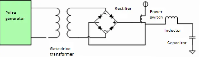
Transformer Isolated Gate Drive Circuit with a Wide Frequency Range.
Coreless transformer technology may be either used to replace half-bridge drivers, which use level shifters, or to replace optocouplers.
Transformer with Multiple Secondary Windings for Totem-Pole Gate Drives. Isolation Amplifier with 1MHz Bandwidth.
Transformers for Maximum Power Transfer.
III.CONCLUSION
The characteristics and some application examples of coreless PCB transformers have been described. Several misunderstandings of coreless PCB transformers have been clarified. Without the limitations of the magnetic cores, coreless PCB transformers offer better performance than their core-based counterparts in the high-frequency operating range. Research into coreless PCB transformers is still in its early stage. It is envisaged that coreless PCB transformers may find applications in many other areas. In particular, the advantages of coreless PCB transformers make them attractive in micro-circuits and in low profile applications in which stringent height requirements have to be met.
Coreless transformer technology is very robust and can easily be combined with innovative functions such as active Miller clamping, two-level turn-off or rail-to-rail outputs. These functions help design engineers to meet their targets in terms of cost, reliability, and time-to-market.
REFERENCES
[1] Radhika Ambatipudi, Hari Babu Kotte, and Dr. Kent Bertilsson ,“Coreless Printed Circuit Board (PCB) Stepdown Transformers for DC-DC
Converter Applications “,International Journal of Electrical, Computer, Energetic, Electronic and Communication Engineering Vol:4, No:10, 2010
[2] Pratibha Kota,”Analysis And Design Methodology For Pcb And Integrated Circuit Pulse Transformer”, submitted to the Faculty of the
Graduate College of the Oklahoma State University, July, 2008.
[3] S. Y. (Ron) Hui, S. C. Tang, H. Chung, “Coreless Printed Circuit Board (PCB) Transformers – Fundamental Characteristics and
Application Potential “, Circuits and Systems, Volume 11, Number 3, Third Quarter 2000
[4] Dominique Bergogne, Christian Martin, Pascal Bevilacqua, Wided Zine, Jean-Christophe Riou, Hilal Izzeddine, Régis Meuret, Bruno
Allard, “Integrated Coreless Transformer for High Temperatures Design and Evaluation”, Power Electronics and Applications (EPE), Sep 2013, Lille, France.
[5] M. Münzer; W. Ademmer; B. Strzalkowski; K. T. Kaschani, “Coreless transformer a new technology for half bridge driver IC´s”, Infineon