APPROACH TO DESIGN, MODELLING AND SIMULATION OF
MULTIPLE EFFECT EVAPORATORS
Chirag R. Thakur1, Lokesh P.Metangle2
1. INTRODUCTION
Evaporation is a process through which solvent is vaporized to obtain desire solute from solution or slurry. It takes place at surface of liquid to change phase from liquid to gases. Multiple effect evaporation is applied in large scale industry to reduce steam consumption . It is an endothermic process where heat is absorbed. Evaporation is a gist process of water cycle and aim only to concentrate the solution. The process of evaporation is higher if carried out at higher temperature. Therefore, for achieving desire product, solution needs to make more concentrated by vaporising the solvent.
It is an integral part of many processes in industries such as pharmaceutical, dairy and food processing, pulp and paper industry, sugar, desalination, etc. Thus either improving design or operation will helps industry to expand its capacity. Evaporation often intrudes upon operations known as drying, crystallization and distillation. In evaporation, the surrounding gas must not be saturated with evaporating substance, component of vapour are not separatedand residue is always liquid which distinguish it from distillation and drying operation respectively. The desire product may or may not be a solid, but heat must be transferred to evaporator to evaporate the solution which distinguishes it from crystallization since production of crystal is not concern. Evaporative cooling is achieved by reducing temperature of liquid through removing heat from vaporised liquid. This process is carried out until equilibrium is obtained.
In this paper, the modelling of evaporator has done for forward feed flow system. The impact of increasing feed flow rate and reduction in effects number has also been discussed.
1.1 Classification of Evaporators
Evaporators are classified on the basis of heat/heating medium such as 1. Solar radiation used for heating
2. Coil, Jackets, Flat plates are used for heating medium
3. Heating medium and evaporating liquid are brought in direct contact
4. Evaporating liquid and heating medium separated through tubular heating surface. There are many types of evaporators and those are enlisting below:
1. Horizontal spray film evaporators (HSFE) 2. Horizontal tube evaporators (HTE) 3. Vertical long tube evaporators
3.1. Rising or climbing film evaporators (RoCFE) 3.2. Falling film evaporators (FFE)
3.3. Rising-falling film evaporators (RFFE) 4. Short tube vertical evaporators
4.1. Inclined tube vertical evaporators (ITTE) 4.2. Basket type vertical evaporators (BTVE) 5. Forced circulation evaporators (FCE)
1,2B.Tech (Chemical Engineering), Department of Chemical Engineering, Priyadarshini Institute of Engg. & Tech., Nagpur
DOI: http://dx.doi.org/10.21172/1.134.03
e-ISSN:2278-621X
6. Plate evaporators (PE)
7. Agitated thin film evaporators or wiped film evaporators (ATFE).
1.2 Parameters needed for selecting any evaporators
Selection of any evaporator is depend upon parameters like heat transfer coefficient, Area of contact, flow pattern, economic, fouling, heat sensitivity, easy cleaning, leakage probability, etc. The parameters affection on selection is shown in table 1.
Parameters → Evaporators
Heat transfer coefficient
Area Flow pattern
Economic Foulin g
Heat sensitivity
Cleaning leakage
HSFE High High Annular,
Stratified
Moderate Min. Nuclease Boiling
Easy Gas
HTE High High - Appropriat
e
Handle High Easy Less
RoCFE High Less - Good Min. High Depend
on viscosity
Less
FFE High less - Good Min. High Easy occur
RFFE High Less - Good Min. High Moderat
e
-
ITTE High Less - Good Min. Depend on
temp. drop
Difficult Less
BTVE High High - less Min. Can’t use for
HS material
Easy -
FCE High Less - Lesser Contro
l
Less Easy Less
PE High High - High for
costly material
Less High Easy High
ATFE Less Limite
d
- Less Min. High Moderat
e
-
Table 1.Parameters for different evaporators
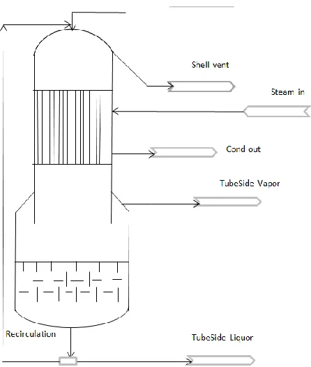
Falling film Evaporator a. Diagram
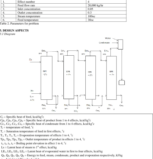
A forward flow sequence is considered where caustic soda is concentrating through falling film evaporator of four effect evaporating system. The operating parameters of this system are given below in table 2.
Sr. no. Parameters Value
1. Effect number 4
2. Feed flow rate 20,000 kg/hr
3. Inlet concentration 0.05
4. Outlet concentration 0.3
5. Steam temperature 100oc
6. Feed temperature 30oc
Table 2. Parameters for problem
3. DESIGN ASPECTS 3.1 Diagram
3.2 Design procedures
Cf = Specific heat of feed, kcal/kgoc
Cp1, Cp2, Cp3, Cp4 = Specific heat of product from 1 to 4 effects, kcal/kgoc
Cc1, Cc2, Cc3, Cc4 = Specific heat of condensate from 1 to 4 effects, kcal/kgoc
Tf = temperature of feed, oc
Ts = Saturation temperature of feed in first effects, oc
T1, T2, T3, T4 = Evaporation temperature of effects 1 to 4, oc
Tp1, Tp2, Tp3, Tp4 = Outlet temperature of product in effects 1 to 4, o
c t1, t2, t3, t4 = Boiling point elevation in effect 1 to 4,
o
c Ls = Latent heat of steam to 1st effect, kcal/kg
LE1, LE2, LE3, LE4 = Latent heat of evaporated water in first to four effects, kcal/kg
QF, QS, QC, QP, QE = Energy to feed, steam, condensate, product and evaporation respectively, kJ/kg
x = Initial total Dissolved solids y = Final total dissolved solids mF = Mass flow rate of feed, kg/hr
The design of multiple effect evaporator includes are, number of tubes, flow rate, mass and energy balance. It’s estimated as follow:
Find amount of product and amount of evaporation by Pm = (mF*x)/y and mF = Pm + Em respectively.
Now, find amount of steam (ms) required for desired separation by assuming steam economy. Thus, ms = Amount of water evaporated (Em) / steam economy (SE)
Now, use mass and energy balance equation for each effects to estimate the amount of product and amount of water evaporate.
mF = Pm + Em (1)
QF + QS = QC + QP +QE (2)
Concentration per effect is determined by,
Xnew = ( Xold* flow rate of feed in that effect) / ( product flow rate from that effect)
Repeat it till desired concentration of product is achieved by assuming new steam economy every time. Area for each effect is varying and found by, A = ( ms* Ls)/ U*ΔT
The number of tubes required in each effect can be found by, N = A / (π*D*L)
The flow rate of pump for each effect can be found by, Q = velocity * no. of tubes * area
3.3 Computation
This system will be analysed in various parameters such as varying flow rates, varying effects number and varying steam economy.
For the system given data is as follows: mF = 20,000 kg/hr
x = 0.05 and y = 0.3
Therefore, amount of product can be calculated as Pm = (mF * x) / y = 3333.33 kg/hr Now, amount of evaporate water can be found by,
mF = Pm + Em So, Em = mF– Pm
Em = 20,000 – 3333.33 = 16,666.67 kg/hr
Now, assuming new steam economy every time, the final steam economy as 3.5. Total steam required, ms = Em / SE
ms = 4761.90 kg/hr
The amount of product and evaporation can be determining by using mass and energy balance equation. For 1st effect:
Since, mF = Pm1 + Em1
20,000 = Pm1 + Em1 ………. (1)
Since, QF + QP = QC1 + QP1 + QE1
(mF*CF*ΔT) + (ms*Ls) = (Cm1*Cc1*ΔT) + (Pm1*Cp1*ΔT) + (Em1*LE1)
So, (20,000*0.95*75)+(4761.90*539.9282) = (4761.90*1.0104*100) + (Pm1*0.91*91) + (Em1*546.2201)
→ 3514941.72 = 52.81*Pm1 + 546.2201*Em1 ……….. (2)
By solving equation (1) and (2), we get Pm1 = 15988.99178 kg/hr Em1 = 4011.008219 kg/hr
Using different mass and energy balance equations for each effect, we can determine the amount of product and evaporation as shown in table 4.3.
Effects no. Mass balance equation Energy balance equation
1. mF = Pm1 + Em1 QF + QP = QC1 + QP1 + QE1
2. Pm1 = Pm2 + Em2 QP1 + QE1 = QC2 + QP2 + QE2
3. Pm2 = Pm3 + Em3 QP2 + QE2 = QC3 + QP3 + QE3
4. Pm3 = Pm4 + Em4 QP3 + QE3 = QC4 + QP4 + QE4
Table 3.1Effects and their mass and energy balance equations
Effect s
Ls and LE for feed Condensate at inlet (C)
Condensate at outlet (C)
Evaporation at outlet
Product at outlet (P)
- Ls or LE T Cc or CF ΔT Cc ΔT LE T CP ΔT
539.9282 100oc 0.95 75oc 1.0104 100oc 546.2201 90oc 0.91 91oc
552.3445 80oc 0.89 81oc 1.0047 80oc 561.3158 65oc 0.88 67oc
561.3158 65oc 0.88 67oc 1.0017 65oc 567.177 55oc 0.87 58oc
Table 3.2 Various operating parameters as per effects
Effects no. First Second Third Fourth
Mass flow rate of product (kg/hr)
15988.99178 11827.30474 7608.23208 3431.48
Mass flow rate of evaporation (kg/hr)
4011.008219 4161.687042 4219.07266 4176.76
Table 3.3 Mass flow rate of product and evaporation
The area required for each effect can be found by using design procedure 5. The value of overall heat transfer will vary as per temperature variation.
Q = U*A*ΔT and Q = ms*L
Where, ΔT is temperature difference between steam inlet and product outlet temperature. Therefore, A = (ms*Ls) / (U*ΔT). The area for each effect is shown in table 4.
Table 4. Area for each effect
Consider a tube having O.D. of 50.8 mm, Length of 6 m and velocity of fluid in pump is 0.04 m/sec (Range 0.02 to 0.05 m/sec) Thus, the No. of tubes required and volumetric flow rate of pump is shown in table 5.
Effects No. of tubes = N = A / (π*D*L) Volumetric Flow rate = Q = v*N*A
1. 213 1738.59 m3/sec
2. 212 1720.2528 m3/sec
3. 185 1308.468 m3/sec
4. 442 7476.872 m3/sec
Table 5. No. of tubes and volumetric flow rate of pump
If three effect systems has been considered then variation in flow rate, area, no. of tubes and volumetric flow rate of pumps variation is shown in table 6.
Effects Feed Flow rate Product flow rate (kg/hr)
Evaporation flow rate (kg/hr)
Area (m2) No. of tubes Volumetric flow rate (m3/sec)
1. 20,000 kg/hr 17152.6100 2847.38 151.40 158 956.84
2. 14068.75084 3083.85 144.00 150 864
3. 10803.7236 3265.02 131.02 137 717.88
Table 6.Three effect system parameters
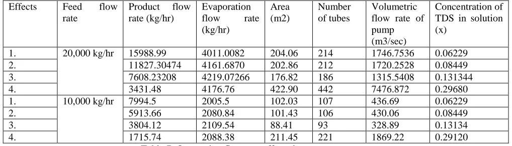
Now, if the feed flow rate is varying then all parameters associated with it will vary except concentration of TDS in solution. This can be shown in table 7.
Effects Feed flow rate
Product flow rate (kg/hr)
Evaporation flow rate (kg/hr)
Area (m2)
Number of tubes
Volumetric flow rate of pump (m3/sec)
Concentration of TDS in solution (x)
1. 20,000 kg/hr 15988.99 4011.0082 204.06 214 1746.7536 0.06229
2. 11827.30474 4161.6870 202.86 212 1720.2528 0.08449
3. 7608.23208 4219.07266 176.82 186 1315.5408 0.131344
4. 3431.48 4176.76 422.90 442 7476.872 0.29680
1. 10,000 kg/hr 7994.5 2005.5 102.03 107 436.69 0.06229
2. 5913.66 2080.84 101.43 106 430.06 0.08449
3. 3804.12 2109.54 88.41 93 328.89 0.13134
4. 1715.74 2088.38 211.45 221 1869.22 0.29120
Table 7. On varying flow rate affected parameters
Effect Area (A), m2 U*ΔT (ms*Ls) Area Calculated
1. A1 1400*9 4761.90*539.9282 204.06 m2
2. A2 1200*9 4011.008219*546.2201 202.86 m2
3. A3 1000*13 4161.687042*552.3445 176.82 m2
Therefore, from above table 8 it’s clear that if we double the flow rate i.e. 10,000 kg/hr to 20,000 kg/hr then its product yield, evaporation rate, Area and number of tubes required doubles whereas volumetric flow rate of pump is four times and concentration remains unaffected.
4. RESULT
By all algorithms we get results as Feed flow rate F: 20,000
Initial TDS x: 0.05 Final TDS y: 0.3 Steam economy: 3.5 No. of effects: 4
Effects Feed
flow rate
Product flow rate (kg/hr)
Evaporation flow rate (kg/hr)
Area (m2)
Number of tubes
Volumetric flow rate of pump (m3/sec)
Concentration of TDS in solution (x)
1. 20,000
kg/hr
15988.99 4011.0082 204.06 214 1746.7536 0.06229
2. 11827.30474 4161.6870 202.86 212 1720.2528 0.08449
3. 7608.23208 4219.07266 176.82 186 1315.5408 0.131344
4. 3431.48 4176.76 422.90 442 7476.872 0.29680
Graph is plotted between Temperature vs. Concentration and Concentration vs. no. of effects.
5. CONCLUSION
This system is operated at steam economy of 3.5. The feed flow rate and effect numbers are changed to evaluate effect on other parameters.The same methodology can be applied to other caustic soda medium to get results.
6. REFERENCES
[1] Kern, D.Q., 1950, Process Heat transfer, McGraw-Hill, USA.
[2] Dhara J. Shah, Prof. C. G. Bhagchandani, 2012, Design, Modelling and simulation of Multiple Effect Evaporators, International Journal of Scientific
Engineering and Technology, Volume No. 1, Issue No. 3, pg:01-05.
[3] McCabe, W.L.., Smith J.C., Harriot P., 1993, Unit Operations of Chemical Engineering, 5th ED., McGraw Hill, USA.
[4] Wikipedia of evaporation <http://en.m.wikipedia.org/wiki/Evaporation>.
[5] Durmus Kaya, H. Ibrahim Sarac, Mathematical modelling of multiple effect evaporators and energy economy, Energy System and Environmental
Research Institute, Energy 32 (2007), Pages 1536-1542.
[6] Badger WL, Banchero JT, Introduction to chemical engineering, New York: McGraw Hills; 1995.
[7] McCabe WL, Smith JC, Unit operation of chemical engineering, New York: McGraw Hills; 1976.
[8] R. Bhargava, S. Khanam, B. Mohanty, A.K. Ray, Simulation of flat falling film evaporator system for concentration of black liquor, Computer and chemical Engineering, 32 (2008), Pages 3213-3223.
[9] S. Khanam, B. Mohanty, Development of a new model for multiple effect evaporator system, Computer and chemical engineering, 35 (2011), Pages
1983-1993.
[10] Wikipedia of falling film evaporator <http://en.m.wikipedia.org/wiki/falling film evaporator>.
[11] Richardson, J.F., Harker J.H., Backhurst J.R., 2002, Particle Technology and separation Processes, 5th Edition, 2 Volume, Linacre House, Jordan Hill,
[12] Sinnott R.K., 2005, Chemical Engineering Design, 4th Edition, 6th Volume, Linacre House, Jordan Hill, Oxford.
[13] Bhatt, B.I. &Vora S.M., 2004, “Stoichiometry”, 4th Edition, Tata McGraw-Hill Publishing Co. Ltd., New Delhi.
[14] Thakore S.B. & Bhatt B.I., 2007, “Introduction to Process Engineering and Design”, Tata McGraw-Hill Publishing Co. Ltd., New Delhi.
[15] Perry R.H. & Green D., 1984, Perry’s chemical Engineering’s Handbook, 6th Edition, McGraw Hill, USA.
[16] Minton P.E., 1986, Handbook of Evaporation Technology, Noyes Publications, USA.
[17] Khanam, S., Mohanty, B., 2010, Placement of condensate flash tanks in multiple effect evaporator system, Desalination 262, pages 64-71.
[18] Khanam, S., Mohanty, B., 2010, Energy reduction schemes for multiple effect evaporator systems, Applied Energy 87, Pages 1102-1111.
[19] Kaya D. &saracHI., 2007, Mathematical modelling of multiple-effect evaporators and energy economy, Energy 32, Pages 1536-1542.
[20] Falling film evaporator working <www.gea.com/enproducts/falling-film evaporator.jsp>.