Application of vertical drains and vacuum
preloading in soft soil stabilization
*Sabahat Ali Khan, ** Mohd Ahmadullah Farooqi
*Assistant Professor, **Associate Professor,
Department of Civil Engineering,
Zakir Hussain College of Engineering and Technology, AMU, Aligarh, India.
ABSTRACT
Infrastructural development effort on soft clay deposits that exhibit excessively low bearing capacity and potential for large settlements poses a challenge for geotechnical engineers. An adequate ground improvement program to achieve proper consolidation is thus a prerequisite for both long- and short-term stability. Pre-construction consolidation using surcharge load alone not only takes too long but also practically quite cumbersome and costly to achieve 90% consolidation. A surcharge preloading along with an arrangement of vertical drains when combined with vacuum pressure makes an attractive ground improvement alternative. This reduces the cost of stabilization and increases the effectiveness of the combined system. The provision of negative pressure in the vertical drains intensifies radial flow of porewater that expedites consolidation. This paper discusses nuances of this system and identifies factors to improve its effectiveness.
Keywords:
Consolidation, PVDs, Soft Soil Stabilization, Vacuum Preloading.
1
Introduction
Demand for development of infrastructure on soft compressible soils is continuously on a rise with increase in population,
especially in the coastal regions of many countries. These soft soil deposits have a low bearing capacity and exhibit large
settlements when subjected to loading. It is therefore inevitable to treat soft soil deposits prior to construction activities in order to
prevent differential settlements and subsequently potential damages to structures for both long- and short-term stability. Even
though there are a variety of ground modification techniques available, the application of preloading with prefabricated vertical
drains (PVDs) is still regarded as one of the preferred methods of practice.
Traditionally, preloading has been the prevalent method of consolidation to increase shear strength and control
post-construction settlement. Since permeability is low and the length of drainage path is equal to the thickness of soil deposit,
preloading alone takes too long to achieve the desired degree of consolidation [1]. In preloading method, the inherent objective is
to reduce the amount of preload to avoid two consequences: 1) reduction in the cost of project 2) collapse of soil mass due to the
fact that most of the soils are weak enough to withstand higher preloads.
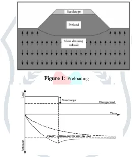
Preloading is the application of surcharge load on the site prior to the construction of the permanent structure, until most
of the primary consolidation has occurred and is commonly used to improve soft clayey soil deposits. The effective surcharge
pressure for preloading can arise from either the weight of imposed fill material e.g., an embankment and/or the application of a
vacuum pressure applied to a saturated soil. Using a vacuum pressure has several advantages over embankment loading, e.g., no
fill material is required, construction periods are generally shorter, and there is no need for heavy machinery. In addition, the
vacuum pressure method does not put any chemical admixtures into the ground and, consequently, it is an environmentally
friendly ground improvement method. Several applications of the use of the vacuum consolidation method to improve soft clayey
2.1 Conventional preloading
The simplest solution of preloading is a preload, e. g. by means of an embankment. When the load is placed on the soft soil, it is
initially carried by the pore water. When the soil is not very permeable, which is normally the case; the water pressure will
decrease gradually because the pore water is only able to flow away very slowly in vertical direction. In order not to create any
stability problems, the surcharge embankment is usually raised as a multi-stage exercise, with rest periods between the loading
stages. The principle is shown in Fig. 1. If the temporary load exceeds the final construction load, the excess refers to as surcharge
load. The temporary surcharge can be removed when the settlements exceeds the predicted final settlement. This should preferably
not happen before the remaining excess pore pressure is below the stress increase caused by the temporary surcharge. By
increasing the time of temporary overloading, or the size of the overload, secondary settlement can be reduced or even eliminated
(Fig. 2). This is because by using a surcharge higher than the work load, the soil will always be in an over consolidated state and
the secondary compression for over consolidated soil is much smaller than that of normally consolidated soil. This will benefit
greatly the subsequent geotechnical design [5].
Figure 1
:
PreloadingFigure 2
:
Resultant Settlement due to preloading2.2 Vacuumpreloading
Sometimes it is not practical to place a fill embankment because the soft soil might be sometimes so weak that even a common 1.5
m embankment might already cause stability problems. In such a case, vacuum preloading method is adopted to improve the
strength of soft clays to accelerate consolidation. In this method the surcharge load is replaced by atmospheric pressure. In its
simplest form the vacuum consolidation method consists of a system of vertical drains and a drainage layer (sand) on top. It is
sealed from atmosphere by an impervious membrane. Horizontal drains are installed in the drainage layer and connected to a
vacuum pump. To maintain air tightness, the ends of the membrane are placed at the bottom of a peripheral trench filled e. g. with
bentonite. Negative pressure is created in the drainage layer by means of the vacuum pump (Figure 3). The applied negative
pressure generates negative pore water pressures, resulting in an increase in effective stress in the soil, which eventually leads to
Figure 3:
Vacuum System (From Vibro Menard: Ground Improvement Specialists)3
Types of vertical drains
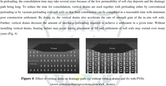
In preloading, the consolidation time may take several years because of the low permeability of soft clay deposits and the drainage
path being long. To reduce the time for consolidation, vertical drains are used together with preloading either by conventional
preloading or by vacuum preloading over soft soils so that final construction can be completed in a reasonable time with minimum
post construction settlement. By doing so, the vertical drains also accelerate the rate of strength gain of the in-situ soft soils.
Further, vertical drains decrease the amount of surcharge/preloading required to achieve a settlement in a given time. Without
installing vertical drains, bearing failure may occur during placement of fill and settlement of soft soils may extend over many
years (Fig. 4)
Figure 4
:
Effect of vertical drain on drainage path; (a) without vertical drains and (b) with PVDs(www.americandrainagesystems.com/wick_drains)
The analyses for vertical drains were previously carried out elsewhere [1-6]. Due to highly efficient drain installation
methods, preloading associated with vertical drains has become an economic and acceptable alternative to other ground
modification techniques.
3.1 Sand Drains
Sand drains are boreholes filled with sands. Diameters, lengths and spacing are designed based on requirement of degree and time
of consolidation desired (TABLE)
TABLE
Types of vertical drains (after Holtz et al., 1991)Drain Type Installation Method
Drain
Diameter
(m)
Typical
Spacing
(m)
Maximum
Length (m)
Sand drain Driven or vibratory closed-end mandrel
(displacement type) 0.15 – 0.6 1 - 5 ≤ 30
sand drains
(“sandwicks”)
auger; rotary wash boring (displacement or
non-displacement)
Prefabricated
band-shaped
drains
Driven or vibratory, closed-end mandrel
(displacement or low displacement)
0.05 – 0.1
(equivalent
diameter)
1.2 – 3.5 ≤ 60
3.2 Pre-fabricated Vertical Drains (PVD)
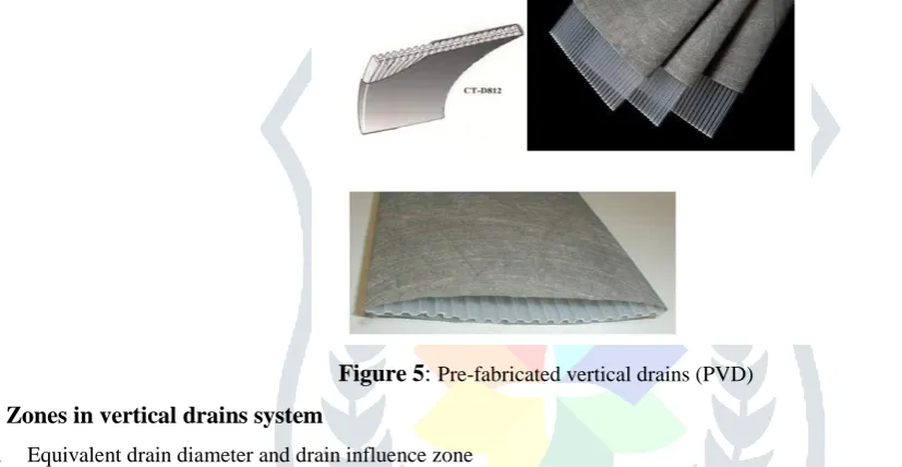
Pre-fabricated vertical drains (PVDs) are a composite geosynthetic system consisting of an inner core and outer filter jacket. The
most commonly used PVD has 100 mm width and 6 mm thickness. The inner core is constructed with polymer-based products
like polypropylene having fabricated flow path of channel shaped on both sides along its length. The outer jacket serves as a filter
to allow passage of water to the inner core preventing clogging by soil particle intrusion. These filter jackets are generally
constructed with nonwoven geotextile. Like sand drains, length and spacing of PVD are designed keeping in view the
requirements.
Figure 5
:
Pre-fabricated vertical drains (PVD)4
Zones in vertical drains system
4.1 Equivalent drain diameter and drain influence zone
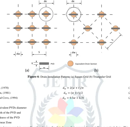
In field, PVDs are typically installed in square and triangular patterns as shown in Fig. 6. The shape of PVDs is rectangular, which
is different from the circular cross section considered in the unit cell theory. Hence, a PVD with polygonal influence zone should
be converted to equivalent cylindrical drain and the equivalent diameter has been approximately calculated by different
researchers as given in Equations (1) to (3).
The PVDs come in large rolls, which are attached to the rig. For the installation of a PVD it is passed through a tubular
steel mandrel and attached to a rectangular anchor plate, which is driven into the soil deposit to the desired depth using hydraulic
rig. The mandrel is then retracted back up, leaving the anchor plate and the drain below at the desired depth. The drain is then cut
S dw
de
t PVD
w
Equivalent Drain Section
(a)
(b)
dw
S
de
Figure 6
:
Drain Installation Patterns (a) Square Grid (b) Triangular GridHansbo, (1970) 𝑑𝑤= 2(𝑤 + 𝑡)/𝜋 (1)
Atkinson, (1981) 𝑑𝑤= (𝑤 + 𝑡)/2 (2)
Long and Covo, (1994) 𝑑𝑤= 0.5𝑤 + 0.7𝑡 (3)
Where,
dw = equivalent PVDs diameter
w = width of the PVD and
t = thickness of the PVD 4.2 Smear Zone
The term ‘smear zone’ is generally referred to as the disturbance that occurs when installing a vertical drain. This causes a
substantial reduction in soil permeability around the drain, which in turn retards the rate of consolidation. The extent of the “smear
zone” caused by mandrel installation can be estimated using the elliptical cavity expansion theory incorporating the modified
Cam-clay model (MCC) [10]. The extent of the smear zone can be defined either by the variation of permeability [11] or by the
variation of the water content [12] along the radial distance from the central drain. In general, the disturbances increase with
increasing cross-sectional area of the mandrel. Therefore, in order to reduce disturbances, the mandrel size should be as close as
possible to that of the drain.
5
Consolidation with vertical drains
When a vertical load is applied, an initial uniform excess pore pressure is assumed to be generated instantaneously throughout the
soil stratum. This excess pore pressure will dissipate gradually or instantaneously depending on the hydraulic conductivity of soil
and drainage condition at the boundaries of the stratum, by vertical drainage through the soil to the horizontal boundaries and/or
by radial drainage into pre-installed vertical drains [8]. The average degree of consolidation indicates how much of the imposed
load is transferred to the effective stress of soil and is defined by:
𝑈𝑡= 𝑆𝑐 (𝑡)
𝑆𝑐 (𝑚𝑎𝑥) (4)
𝑈𝑡= 𝑢𝑖−𝑢𝑡
𝑢𝑖 = Initial excess pore pressure upon application of a vertical load.
𝑢𝑡= Average excess pore pressure at a particular time.
6
Consolidation without vertical drain
Terzaghi’s theory of one-dimensional consolidation predicts the excess pore pressure under vertical drainage alone. Based on the
above Equation (5), Terzaghi’s theory gives the following expression for the average degree of consolidation due to vertical
drainage.
𝑈𝑣(%) = [1 − 8 𝜋2∑
1 (2𝑁+1)2𝜀
−−(2𝑁+1)2𝜋2𝑇𝑣
4
𝑁=𝛼
𝑁=0 ] 𝑋100 (6)
This equation can be written as follows:
𝑈𝑣(%) = 𝑓(𝑇𝑣) (7)
It shows that degree of consolidation is a function of time factor,
In which,
𝑈𝑣= Average degree of consolidation due to vertical drainage alone
𝑇𝑣= 𝐶𝑣𝑡
𝑑2 (8)
d = Length of longest drainage path 𝑡 = time from load application
𝐶𝑣= Coefficient of consolidation due to vertical drainage
7
Consolidation with vertical drain due to radial drainage only
Barron [8] arrived at the solution from the excess pressure at any radial distance from the drain and at any time during
consolidation. Based on equation (5) and the assumption of equal vertical strain, the following equation can be established for the
average degree of consolidation due to horizontal drainage:
𝑈𝑟= 1 − 𝜀
−8𝑇𝑟
𝐹(𝑛) (9)
𝑇𝑟= 𝐶𝑣𝑟𝑡
𝐷2 (10)
In which,
𝑇𝑟= Time factor for radial flow
𝐶𝑣𝑟= Coefficient of consolidation for radial consolidation
D = Diameter of equivalent cylinder of soil drained by each vertical drain = 1.13 x drain spacing for square grid,
= 1.05 x drain spacing for triangular grid
𝐹(𝑛) = ( 𝑛2
𝑛2−1) ln(𝑛) −
3𝑛2−1
4𝑛2 (11) In which,
𝑛 = 𝐷/d
d = drain diameter = drain circumference/π
Regarding the well resistance, the effect depends on the hydraulic conductivity of the vertical drains and surrounding
undisturbed soil as well as the drain diameter.𝐹(𝑛)is a function mainly related to drain spacing and size and the extent of soil
disturbance due to drain installation (smear effect). It has more than one version as addressed in detail in Barron [8]. The basic
form of 𝐹(𝑛) for ideal drain with no smear effect can be expressed as follows:
8
Consolidation under combined vertical and horizontal drainage
Presence of vertical drains does not prevent the vertical drainage of water in the normal way. In reality, both vertical and
horizontal drainage takes place simultaneously. The average degree of consolidation for combined vertical and radial water flow,
U can be calculated to be:
(1 − 𝑈) = (1 − 𝑈𝑟)(1 − 𝑈𝑣) (12)
In which,
𝑆𝑡= 𝑆𝑢𝑙𝑡 (𝑈𝑣𝑟) (13)
9
Conclusion
A system of prefabricated vertical drains (PVDs) combined with application of preload and vacuum is an effective method for
accelerating soil consolidation. The vacuum pressure propagating along the PVDs increases the hydraulic gradient and acts as an
additional surcharge load. Therefore, this system accelerates the consolidation process, and the height of the embankment can be
significantly reduced to achieve the same degree of consolidation. This is a very useful and widely accepted technique for
improvement of soft soils that possess low hydraulic conductivity, less shear strength and reduces construction time considerably.
The refinement in the mandrel size and shape could be able to reduce the remolding effect of the soil around the drain, which
would reduce the size of smear zone resulting in increased efficiency of the system.
REFERENCES
[1] Holtz, R. D., et al. 1991. Prefabricated Vertical Drains: Design and Performance, CIRIA ground engineering report: ground
improvement. Oxford: Butterworth – Heinemann Ltd.
[2] Bergado, D. T., Chai, J. C., Miura, N., and Balasubramaniam, A. S. (1998) “PVD improvement of soft Bangkok clay with
combined vacuum and reduced sand embankment preloading.” Geotech. Eng., 29(1), 95–121.
[3] Chu, J., Yan, S. W., and Yang, H. (2000). “Soil improvement by the vacuum preloading method for an oil storage station”
Geotechnique, 50(6), 625–632.
[4] Tang, M., and Shang, J. Q. (2000). “Vacuum preloading consolidation of Yaogiang Airport runway.” Geotechnique, 50(6),
613–623.
[5] Chu, J., Bo, M. W., Choa, V. 2004. Practical considerations for using vertical drains in soil improvement projects. Geotextiles
and Geomembranes 22 (2004) 101-117.
[6] American Drainage Systems, Inc. (2006). Vertical wick drains [Online]. Available:
http://www.americandrainagesystems.com/wick_drains.htm.
[7] A. K. Bhattacharya, S. Basack, A review of the use of the pre-loading technique and vertical drains for soil consolidation,
Proceedings of Indian Geotechnical Conference, December 15-17, 2011, Kochi.
[8] Barron, B. A. (1948), “Consolidation of Fine Grained Soil by Drain Wells”, Trans. of Am. Soc. Civ. Engrg., 113, 712-748.
[9] Budhu Muni, Soil Mechanics and Foundations, 3rd Edition ISBN: 978-0-470-91191-4, February 2011, John Wiley.
[10] Ghandeharioon, A., Indraratna, B., and Rujikiatkamjorn, C. (2010). Analysis of soil disturbance associated with
mandrel-driven prefabricated vertical drains using an elliptical cavity expansion theory. International Journal of Geomechanics, ASCE.
10(2), 53-64.
[11] Indraratna, B. and Redana, I. W. (1998). Laboratory determination of smear zone due to vertical drain installation.” J.
Geotech. andGeoenviron. Engng. 124(2): 180-185.
[12] Sathananthan, I. and Indraratna, B. (2006). Laboratory Evaluation of Smear Zone and Correlation between Permeability and