A Step-by-Step Design of Vibratory Apparatus
for Ultrasonic-Assisted Drilling
Ngoc-Hung Chu1, Quoc-Huy Ngo2 & Van-Du Nguyen3,*
1 Faculty of Internaltional Training, Thai Nguyen University of Technology, Viet Nam
E-mail: [email protected]
2 Faculty of Mechanical Engineering, Thai Nguyen University of Technology, Viet Nam
E-mail: [email protected]
3Faculty of Mechanical Engineering, Thai Nguyen University of Technology, Viet Nam, *Corresponding Author E-mail: [email protected]
Abstract: This paper presents a mechanical design approach, fabrication of a vibratory apparatus which can be applied to vibration assisted drilling (UAD) process. An experimental study was also implemented to validate the ability of the tool holder for twist drill bits in order to superimpose the ultrasonic vibration into the drill bit in UAD. The structure and dimensions of the vibratory components were determined by applying the theory of ultrasonic wave transmission, and then being refined by the modal analysis and practical impedance measurement techniques. The designed and fabricated vibratory unit was then practically checked in drilling. It was found that the device can be effectively used for further experimental studies as well for real production. The design process is depicted step-by-step so that can be easily followed as a practical guideline for similar studies.
Keywords: Ultrasonic Horn, Vibration Assisted Machining, Drilling, Mechanical Design
I. INTRODUCTION
Drilling is a preferable machining process, as it takes about one-third of all manufacturing operations [1]. In addition, dry drilling as well as other dry cutting operations become more preferable as an environmental friendly machining technique. However, this trend would give more challenges in deep drilling of brittle materials [2]. During dry drilling of brittle materials, long and ductile chips tend to bend and coil and thus cause packing of the drill flutes, interferes with chip ejection [3]. At the deeper drilled depth, the increased amount of chips would fill up the flutes, leading to chip-clogging and thus cause the total torque increase exponentially [4-9]. The addition of such chip evacuation torque results in excessive torsional stress, leading to a common failure of the tools known as drill breakage [6, 9, 10]. Whenever the drill broken inside the drilled hole, it is difficult to take out the broken part of the tool from the workpiece, causing catastrophic damage to the parts as well as a considerable economic lost [11].
aluminum alloy 6061 has recently been found in several experimental studies of Nguyen and Chu [21-24].
The design of the vibratory unit for clamping the cutting tool for rotary ultrasonic assisted machining is a critical issue. A vibratory unit used in UAD typically consists of a transducer, a horn or sonotrode, the drill bit attached to the horn. Despite abundant studies have been made for designing either the transducer or the horn [25, 26] [27-29], the design steps of the whole vibratory design process has not been presented clearly, making difficult for later investigations for reference.
This paper presents the design approach of a typical vibratory unit with the drilling bit attached to the horn. Each step of the whole design process is depicted in detail. Experimental validation of the cutting improvement when applying ultrasonic vibration onto the drilling process by mean of such designed and fabricated vibratory unit is also presented.
II. DESIGN OF THEVIBRATORYAPPARATUS
A. Structure Design
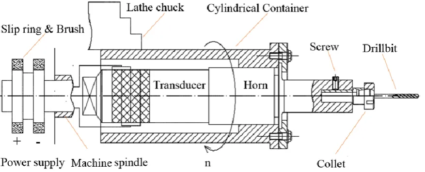
A typical ultrasonic vibratory unit typically consists of three major components: a transducer, a horn and an actuator. The structure of the whole unit for drilling applications can be proposed as shown in Figure 1.
Figure 1. Proposed structure of the vibratory unit
from the manufacturer. In this study, a commercial ultrasonic transducer working with working frequency of 25 kHz was selected. Details of this transducer are depicted in Table 1. The whole vibratory unit then will be carefully designed and fabricated so as to work with such provided frequency at 25 kHz of the chosen transducer for transfer of maximum energy.
Table 1. Selected Ultrasonic Transducer
Contents Specifications
Model DW5025-4Z
Frequency (kHz) 25
Ceramic diameter (mm) 50
Ceramic quantity 4
Power (W) 200
Amplitude (m) 5
The horn, which is sometimes called as the centroid, plays an important role in transmission, concentration and amplification of the ultrasonic vibration from the transducer into the tool. Hence, geometric characteristics of the horn must be carefully determined and validated. It would be worth noting that any changes in dimension of the tool and/or assembly geometry will direct effect on the resonant frequency and thus on the working performance of the whole unit.
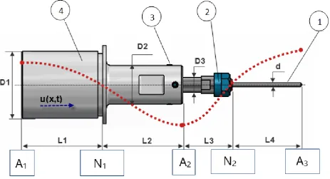
The assembly of the horn and the cutting tool would be further scrutinized in detail as shown in Figure 2.
Figure 2. Assembly of the horn and the drill bit
In Figure 2, the tool 1 can be attached to the horn 4 by mean of a collet 2. The collet is fixed inside the horn by screws 3. The longitudinal dimensions Li (i=1-4) must be computed so as to obtain the
diameter of the the drill bit, d. In this study, a collet ER11, which can be used for dill bits ranged from 1 to 7 mm diameter, was chosen. The detailed calculation process to determine the dimensions of the structure is presented in the next section.
B. Component Design
This design step aims to determine dimension of each components shown in Figure 2 above. Several important parameters of the calculation process are shown in Tanle 2.
Table 2. Propeties of vibratory parts
Part Metarials Elasticity E (GPa) Density (kg/m3) Sound velocity (m/s)
Horn Ti-6Al-4V-Grade 5 113.8 4430 5068
Collet 1065 carbon steel (ER11)
200 7850 5048
Drill HSS (d = 3mm) 207 8300 4994
1) Initial dimensions of the horn dimension
Dimensions of a stepped cylindrical horn can be carried out by using theory with half-wave length principle, which have been well known in several literatures (See for example in [31, 32]. The basic calculation is briefly described as below.
Assigning as the length of the ultrasonic wave, c1 for the sound velocity transmitted in the horn
material, as the angular frequency; 1 and 2 as the particle displacement at x=0 and at x=L,
respectively; E and as the Young's modulus of elasticity and the density of the horn material, respectively; then the lateral displacement, ux, can be expressed as [33]:
( )
( )
− = = 2 / 4 / cos ) ( cos 4 / 0 cos cos 2 1 x for t c x L x for t c x x x (1)The amplifcation factor for the half-wave, double-cylinder horn is therefore determined as
2 1 1 2 S S
= (2)
where S1 and S2 as the cross-sectional area of the horn at x=0 and at x=L, respectively.
For the horn made by Ti-6Al-4V with the characteristic of sound transmission velocity of 5068 m/s (See Table 2), the total length of the horn can be determined as:
mm f
c
LHorn 101.36
25000 * 2 5068 * 2 2 1
1 = = =
= (3)
The location of a special structure used to clamp the horn, called "nodal plane", is the position where particle displacement is zero (node = 0) thus can be taken from the following equation:
mm L
L L c
node 50.7
2 0
cos 1 2
1
= = = =
(4)
The next sub-step is to determine the two diameters of the stepped horn. Chosen the small diameter D2 so as to have enough space for placing the collet body inside. Chosen the gain factor of the horn
G, one can then determine the larger diameter of the horn as:
) (
2
1 D G mm
D = (5)
In this study, D1 and D2 were selected as 54 and 31 mm, respectively, making the gain factor of 3.
Consequently, given the vibration amplitude at the output end of the transducer as 5 micrometers, the amplitude at the end of the horn should be 15 micrometers.
2) Initial lengths of the collet and drill bit assembly
The lengths L3 and L3, corresponding to the free segments of the collet and the drill bit, should be carried out so as the vibration amplitude at the drill tip is maximum (See Figure 2). Applying Equation (1) with the values of sound transmission velocities in the collet and the drill bit are of 5048 m/s and 4994 m/s, respectively, we can get L3=50 mm and L4=58 mm.
The initial dimensions obtained will be then used for the final step of the design process.
3) Refined design
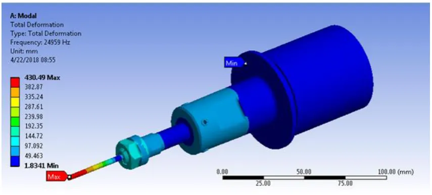
The calculated values above are carried out for a horn with two cylindrical steps, without nodal flange dimension and any modified structures required to clamp the collet as well as the drill bit. Such modification in the structure makes change in the frequency resonant of the whole system. It would be noted that, that frequency has to be equal to the original resonant frequency of the selected transducer. Consequently, the whole vibratory unit must be refined using Finite Element Analysis (FEA) technique, until the desired results are achieved. At first, a 3D model of the whole unit, including the horn, the screws, the collet and the tool is built and then import into a Computer Assisted Engineering (CAE) environment which supports FEA. Several available CAE software can be employed, such as ANSYS, Abaqus. In this study, ANSYS R15 was adopted. Modal analysis technique can be applied to check with how changes in the mechanical structure effect on the resonant frequency. To increase the resonant frequency, shortening the total length of the horn was made. In case of reducing the resonant frequency, the length of the segment of the horn with bigger diameter should be shortened . Figure 3 shows the final results obtained. As the resonant frequency obtained at 24959 Hz, very close to the resonant frequency of the transducer, the final dimensions were then used to fabricate the parts.
III. RESONANTFREQUENCYCHECKING
It would be noted that, the fabricating process would have several errors in the part dimensions and forms, as well in the shared lengths between the collet and the horn, the collet and the drill bit, will significantly change the resonant frequency of the whole system.
mean of the total electrical impedance of the whole assembly. In this study, the impedance was measured by the V-I method [34]. A simple measurement circuit is shown in Figure 4.
Figure 3. A modal analysis of the horn assembled with the tool bit
Figure 4. A simple circuit to measure ultrasonic impedance using V-I method
Figure 5. The measured impedance of the whole assembly
A sinusoidal signal with amplitude of 2 V and the swept frequency range from 24000 Hz to 27500 Hz with incremental steps of 50 Hz each was applied to the transducer. Sweeping frequencies and output signal VA1, VA2 were implemented by means of corresponding functions of a PicoScope device. The
impedance of the ultrasonic actuator can be approximated as:
2
1 1 2 2
2 2
2 cos
A ref X
A A A A
V R Z
V V V V
=
− + (6)
IV. EXPERIMENTALEVALUATION
A. Experimental setup
A photograph of the experimental setup is shown in Figure 6.
Figure 6. A photo of the experimental setup
In Figure 6, an universal lathe machine (V-Turn 410) was used for implementing the experimental tests. Workpieces were made in the form of square bars with dimensions of 10x10x30 mm3, made from Al6061-T6. The drilling tests were carried out using HSS twist drill bits with a diameter of 3 mm and under dry cutting conditions. The drilling torque was measured by a torque sensor model PCB-2508-03A. A ultrasonic generator model MPI WG-3000 WG was used to convert 50 Hz electrical supply to high-frequency electrical impulses. The frequency range of the generator is 20 to 40 kHz and the frequency step is 1 Hz.
B. Experimental results
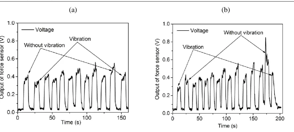
In order to check if the vibratory unit can bring about the positive effects on the drilling process, the ultrasonic excitation was swiched off then on after about one second. The output signal from the force sensor, reflecting the changes in the thrust force, was recorded. Figure 6 depicts two examples of the results.
The spindle spped of 1000 rpm and the feeding rate of (a)0.05 mm/rev and (b) 0.085 mm/rev were applied
(a) (b)
Figure 7. Thrust force signal changes.
V. CONCLUSION
A step-by-step of the design process, refine, checking and experimental validation of an ultrasonic vibratory unit used in assistance of drilling was investigated in this study. The following remarks can be concluded:
- The transducer can be chosen based on the power required and with a certain frequency;
- An initial design step should be done to provisionally determine the segment lengths of the solid ultrasonic horn based on the frequency of the transducer;
- After making the detail structure of the horn and other constructions required to attach the cutting tool, finite element analysis should be done to adjust and refine the structure so as the resonant frequency of the whole system approximately equal to that of the transducer;
- The resonant frequency of the assembled unit can be checked by measuring the electrical impedance of the transducer attached to the horn and the tool;
- The resonant frequency of the whole unit can be adjusted by changing the segment lengths of the horn;
- Further study should be done to develop a mathematical model of the relationship between the horn with attachment structures and the resonant frequency of the whole.
ACKNOWLEDGEMENT
This study has been supported by a scientific project from Thai Nguyen Univesity, Vietnam, under the Grant number DH2013-TN02-09.
Conflict of interest: The authors declare that there has no conflict of interest.
REFERENCES
[1] H. S. Liu, B. Y. Lee, and Y. S. Tarng, "In-process prediction of corner wear in drilling operations," Journal of Materials Processing Technology, vol. 101, no. 1, pp. 152-158, 2000/04/14/ 2000.
[2] P. Roy, S. K. Sarangi, A. Ghosh, and A. K. Chattopadhyay, "Machinability study of pure aluminium and Al–12% Si alloys against uncoated and coated carbide inserts," International Journal of Refractory Metals and Hard Materials, vol. 27, no. 3, pp. 535-544, 2009.
[3] T. J. Drozda, Tool and Manufacturing Engineers Handbook: Machining. Society of Manufacturing Engineers, 1983.
[4] A. Arzur-Bomont, M. Confente, E. Schneider, O. Bomont, and C. Lescalier, "Machinability in drilling mechanistic approach and new observer development," International Journal of Material Forming, vol. 3, no. S1, pp. 495-498, 2010.
[5] F. Ke, J. Ni, and D. A. Stephenson, "Chip thickening in deep-hole drilling," International Journal of Machine Tools and Manufacture, vol. 46, no. 12-13, pp. 1500-1507, 2006.
[6] J. C. Mellinger, O. Burak Ozdoganlar, R. E. DeVor, and S. G. Kapoor, "Modeling Chip-Evacuation Forces and Prediction of Chip-Clogging in Drilling," Journal of Manufacturing Science and Engineering, vol. 124, no. 3, p. 605, 2002.
[7] J. C. Mellinger, O. B. Ozdoganlar, R. E. DeVor, and S. G. Kapoor, "Modeling Chip-Evacuation Forces in Drilling for Various Flute Geometries," Journal of Manufacturing Science and Engineering, vol. 125, no. 3, p. 405, 2003.
[8] T. Nagao, Y. Hatamura, and M. Mitsuishi, "In-Process Prediction and Prevention of the Breakage of Small Diameter Drills Based on Theoretical Analysis," CIRP Annals, vol. 43, no. 1, pp. 85-88, 1994/01/01/ 1994.
[9] R. J. Furness, A. G. Ulsoy, and C. L. Wu, "Feed, Speed, and Torque Controllers for Drilling," Journal of Engineering for Industry, vol. 118, no. 1, p. 2, 1996.
[10] S. Ravisubramanian and M. S. Shunmugam, "Investigations into peck drilling process for large aspect ratio microholes in aluminum 6061-T6," Materials and Manufacturing Processes, vol. 33, no. 9, pp. 935-942, 2017.
[11] Y. J. Choi, M. S. Park, and C. N. Chu, "Prediction of drill failure using features extraction in time and frequency domains of feed motor current," International Journal of Machine Tools and Manufacture, vol. 48, no. 1, pp. 29-39, 2008/01/01/ 2008.
[12] D. E. Brehl and T. A. Dow, "Review of vibration-assisted machining," Precision Engineering, vol. 32, no. 3, pp. 153-172, 2008.
[13] S. Amini, H. Paktinat, A. Barani, and A. F. Tehran, "Vibration Drilling of Al2024-T6," Materials and Manufacturing Processes, vol. 28, no. 4, pp. 476-480, 2013.
[14] B. V. Azghandi, M. A. Kadivar, and M. R. Razfar, "An Experimental Study on Cutting Forces in Ultrasonic Assisted Drilling," Procedia CIRP, vol. 46, pp. 563-566, 2016.
[15] S. S. F. Chang and G. M. Bone, "Thrust force model for vibration-assisted drilling of aluminum 6061-T6," International Journal of Machine Tools and Manufacture, vol. 49, no. 14, pp. 1070-1076, 2009/11/01/ 2009.
[16] X. Li, A. Meadows, V. Babitsky, and R. Parkin, "Experimental analysis on autoresonant control of ultrasonically assisted drilling," Mechatronics, vol. 29, pp. 57-66, 2015.
[17] X. F. Li, Z. G. Dong, R. K. Kang, Y. D. Wang, J. T. Liu, and Y. Zhang, "Comparison of Thrust Force in Ultrasonic Assisted Drilling and Conventional Drilling of Aluminum Alloy," Materials Science Forum, vol. 861, pp. 38-43, 2016.
[18] A. Barani, S. Amini, H. Paktinat, and A. Fadaei Tehrani, "Built-up edge investigation in vibration drilling of Al2024-T6," Ultrasonics, vol. 54, no. 5, pp. 1300-10, Jul 2014.
[19] S. S. F. Chang and G. M. Bone, "Burr height model for vibration assisted drilling of aluminum 6061-T6," Precision Engineering, vol. 34, no. 3, pp. 369-375, 2010.
[20] R. Neugebauer and A. Stoll, "Ultrasonic application in drilling," Journal of Materials Processing Technology, vol. 149, no. 1-3, pp. 633-639, 2004.
[22] N.-H. Chu, V.-D. Nguyen, and T.-V. Do, "Ultrasonic-Assisted Cutting: A Beneficial Application for Temperature, Torque Reduction, and Cutting Ability Improvement in Deep Drilling of Al-6061," Applied Sciences, vol. 8, no. 10, p. 1708, 2018.
[23] N.-H. Chu, V.-D. Nguyen, and Q. H. Ngo, "Machinability enhancements of ultrasonic assisted deep-drilling of aluminum alloys," Machining Science and Technology, Accepted vol. (In press), 2018. [24] N.-H. Chu and V.-D. Nguyen, "The Multi-Response Optimization of Machining Parameters in the
Ultrasonic Assisted Deep-Hole Drilling Using Grey-Based Taguchi Method," International Journal of Mechanical and Production Engineering Research and Development, vol. 8, no. 5, pp. 417-426, 2018. [25] K. F. Graff, "Power ultrasonic transducers: principles and design," in Power Ultrasonics, 2015, pp.
127-158.
[26] L.-C. Z. Wei-Xing Xu, "Ultrasonic vibration-assisted machining principle, design and application," Adv. Manuf, vol. 3, pp. 173-192, 2015.
[27] M. Nad, Ultrasonic horn design for ultrasonic machining technologies. 2010.
[28] S. Kumar Padmanaban, Design and Analysis of Ultrasonic Welding Horn using Finite Element Analysis. 2017, pp. 74-87.
[29] R. Dipin Kumar, M. Roopa Rani, and S. Elangovan, Design and Analysis of Slotted Horn for Ultrasonic Plastic Welding. 2014, pp. 859-863.
[30] Z. Yan, Q. Fang, J. Huang, B. He, and Z. Lin, "Considerations and guides of the wattmeter method for measuring output acoustical power of Langevin-type transducer systems — II: experiment," Ultrasonics, vol. 35, no. 7, pp. 543-546, 1997/11/01/ 1997.
[31] M. Short and K. F. Graff, "16 - Using power ultrasonics in machine tools," in Power Ultrasonics, J. A. Gallego-Juárez and K. F. Graff, Eds. Oxford: Woodhead Publishing, 2015, pp. 439-507.
[32] Q.-H. Ngo, N.-H. Chu, and V.-D. Nguyen, "A Study on Design of Vibratory Apparatus and Experimental Validation on Hard Boring with Ultrasonic-Assisted Cutting," International Journal of Advanced Engineering Research and Applications, vol. 3, no. 10, pp. 383-396, 2018.
[33] D. Ensminger and F. B. Stulen, "Ultrasonics Data, Equations and Their Practical Uses," Taylor & Francis Group, LLC, 2009.
[34] Q. Pan, D. Xiao, M. Deng, H. Ren, Y. Xu, and C. Xu, "A voltage-current method of measuring ultrasonic transducer impedance," in 2013 Far East Forum on Nondestructive Evaluation/Testing: New Technology and Application, 2013, pp. 125-128.
________________________________________________________________________________________