www.ijaera.org 2016, IJA-ERA - All Rights Reserved 160
Synthesis and Characterization of (Fe,Co)
Nano-Particles and application as Heat
Transfer Enhancement technique
Mandeep1, Dr. Prinam Anuradha2 and Dr. Pradip Sarawadey31M.Tech Scholar, Mechanical Engg. Department, U.I.E.T Kurukshetra Uni. Kurukshetra
2Assistant Professor, Mechanical Engg. Department, U.I.E.T Kurukshetra Uni.Kurukshetra
3Assistant Professor, Physics Department, University of Mumbai, Mumbai, India
Abstract: Nanostructured materials have proved their superiority over wide range of applications due to their interesting size-dependent chemical and physical properties compared to particles of size in the range of micrometer. Iron-oxide and cobalt oxide Nano-particles have a lot of potential uses in many technological fields. In this study the Nano-particles are synthesize via solvo-thermal processes using different precursors and urea as reducing agent. Samples were characterized by UV-visible spectrum, X-ray diffraction, scanning electron microscope (SEM), Fourier transform infrared spectroscopy (FTIR), Field Emission Scanning Electron Microscope(FESEM).These Nano-particles were suspended in base fluid which is water in this case and made to flow in setup of parallel flow concentric tube heat exchanger and effects were noted.
Keywords: Solvo Thermal, Precursor, LMTD, Enhancement, Autoclave
I. INTRODUCTION
The introduction of Nano-fluid by Choi opened gates for many possibility in different field of science and technology[1]. Oxide Nano-particles caught our eyes due to their vast potential in many areas like solar energy conversion, heat transfer enhancement, heterogeneous catalyst [2]. Solvo thermal technique is used for synthesis of iron oxide and cobalt Nano oxide particles. Solvo thermal synthesis is a technique where the reaction occurs in a pressure vessel that allows normal solvents such as water to be heated to temperatures far in excess of their normal boiling points. The solvo thermal reduction route used widely to prepare high-quality crystallized [3, 4]. The heat transfer capacity of Nano fluid very much depend upon thermal conductivity on Nano particle and base fluid. Metallic oxide Nano particles are less than metallic Nanoparticles and increases the interfacial resistance [5].Through parallel flow concentric tube heat exchanger test is done to check the contribution of iron oxide and cobalt oxide in heat enhancement. So enhanced thermo physical properties such as thermal conductivity, thermal diffusivity, viscosity, and convective heat transfer coefficients compared to those of base fluids like oil or water can be used in different heat exchanger [6, 7]. To check the heat transfer enhancement a test was conducted where the fluid is made to run through counter flow concentric tube heat exchanger and LMTD of different fluids were noted down. As we know, higher the LMTD of fluid higher will be the heat transfer between the fluids.
II. EXPERIMENTALSECTION
A) SYNTHESIS OF COBALT OXIDE NANO-PARTICLES
www.ijaera.org 2016, IJA-ERA - All Rights Reserved 161
rpm for four hours. After 5 hours& 30 mints stop heating and stir for 10 mints. Cool down the autoclave. After cooling down, remove the solution from Teflon vessel. Transfer the solution into beaker. Cool the solution. Put the solution into centrifuge tube. These tubes placed in centrifuging machine. Centrifuge the solution for 30 min at 5000 rpm. Then after centrifugation particle settle down, remove the upper solution. Wash the solution two or three times at same rpm. Moisturize nanoparticles are placed in Furner at 800C temperature till all the moisture removed from the particles.
B) SYNTHESIS OF NANO-CUBES IRON OXIDE PARTICLES
Firstly wash the beakers with double distilled water. Solution A: Add 0.3 g of urea in 20 ml of water followed by stirring of 5 mints., at 500 rpm., after that add 0.5g of CTAB then stir the solution for 30 mints. After 30 mints add 20 ml of cyclohexane and stirring of 5 mints. Solution B:In 10 ml double distilled water, add iron precursor 0.2703 g (0.001mol) Fe (III) nitrate Nona hydrate. Stir sol. B for 5 mints. Add sol. B drop wise in sol. A and do stirring for 5 mints. Transfer the solution to the autoclave. Set the pressure of autoclave i.e. two bar, maintain the temperature i.e. 900C and set the rotation at 1000 rpm for four hours. After four hours stop heating and stir for 10 mints. Cool down the autoclave. After cooling down, remove the solution from Teflon vessel. Transfer the solution into beaker. Cool the solution. Put the solution into centrifuge tube. These tubes placed in centrifuging machine. Centrifuge the solution for 30 min at 5000 rpm. Then after centrifugation particle settle down, remove the upper solution. Wash the solution two or three times at same rpm. Moisturize nanoparticles are placed in Furner at 800C temperature till all the moisture removed from the particles.
C) SYNTHESIS OF DISTORTED IRON OXIDE PARTICLES
Firstly wash the beakers with double distilled water. Solution A: Add 0.3 g of urea in 20 ml of water followed by stirring of 5 mints. at 500 rpm., after that add 0.5g of CTAB then stir the solution for 30 mints. After 30 mints add 20 ml of cyclohexane and stirring of 5 mints. Solution B:In 10 ml double distilled water, add iron precursor 0.2703 g (0.001mol)FeCl3.6H2O. Stir sol. B for 5 mints. Add sol.
B drop wise in sol. A and do stirring for 5 mints. Transfer the solution to the autoclave. Set the pressure of autoclave i.e. two bar, maintain the temperature i.e. 900C and set the rotation at 1000 rpm for four hours. After four hours stop heating and stir for 10 mints. Cool down the autoclave. After cooling down, remove the solution from Teflon vessel. Transfer the solution into beaker. Cool the solution. Put the solution into centrifuge tube. These tubes placed in centrifuging machine. Centrifuge the solution for 30 min at 5000 rpm. Then after centrifugation particle settle down, remove the upper solution. Wash the solution two or three times at same rpm. Moisturize nanoparticles are placed in Furner at 800C temperature till all the moisture removed from the particles.
D) SYNTHESIS OF NANOROD IRON OXIDE PARTICLES
www.ijaera.org 2016, IJA-ERA - All Rights Reserved 162 E) CHARACTERIZATION AND EXPERIMENTAL OBSERVATION
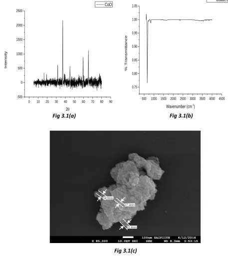
i) COBALT OXIDE NANOPARTICLES
From fig 3.1 (a)The XRD of cobalt oxide calcine at 4000c gives peaks at (2ѳ= 16.30, 190, 31.20, 360, 44.70, 600, 65.920) from which we can say that cobalt oxide nanoparticles have cubic structure[11, 12] (b)The FTIR of sample gives us FT-IR spectra of samples 592 cm-1 which confirm the formation of Co3O4 spinel oxide[13, 14](c) The average size of nano particles formed comes in range of 30nm.
0 10 20 30 40 50 60 70 80 90
-500 0 500 1000 1500 2000 2500
Int
en
sity
2
CoO
500 1000 1500 2000 2500 3000 3500 4000 4500 0.75
0.80 0.85 0.90 0.95 1.00 1.05
% Tra
nsm
ittan
ce
Wavenumber (cm-1)
Cobalt Oxide
Fig 3.1(a) Fig 3.1(b)
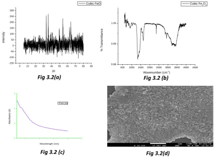
www.ijaera.org 2016, IJA-ERA - All Rights Reserved 163 ii) CUBIC IRON OXIDE NANO-PARTICLES
From Fig 3.2 (a)XRD taken after calcination at 4000c gives peak at 250 which is α-Fe2O3 because
transformation of γ-Fe2O3 to α-Fe2O3 takes place at high temperature.[15](b)FTIR data shows different
peak at 1480 cm-1,1516 cm-1,1720 cm-1, 2330 cm-1,2780 cm-1, and 3420 cm-1 wave numbers.(c)UV-visible spectrum of γ-Fe2O3 [16](d) FESEM of sample showing cubic shape iron oxide nano-particles.
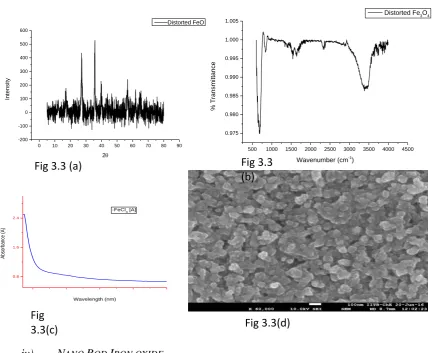
iii) DISTORTED SHAPE IRON OXIDE NANO-PARTICLES
From fig 3.3 (a)XRD of sample give peak at(2ѳ= 29.50, 38.360,420&58.640) and the heighest peak
intensity tells that this is α-Fe2O3. [17] (b) FT-IR peak at ~3439.4 cm−1 is attributed to the stretching
vibrations of Fe-OH, which is assigned to OH− absorbed by Fe2O3 nanoparticles. And the peak at ∼584.3 cm−1 is attributed to the Fe-O bond vibration of Fe3O4.[18](c)UV-spectal shows that the sample
before calination was γ-Fe2O3. (d)SEM image showing the destorted shape of iron oxide and give
particle size upto 24nm.
0 10 20 30 40 50 60 70 80 90 -150
-100 -50 0 50 100 150 200 250 300
Int
en
sity
2
Cubic FeO
500 1000 1500 2000 2500 3000 3500 4000 4500 0.98
0.99 1.00
% Tra
nsm
ittan
ce
Wavenumber (cm-1
)
Cubic Fe3O4
0 1 2 3
Abs
orbance (A)
Wavelength (nm) -FeN [A]
Fig 3.2(a) Fig 3.2 (b)
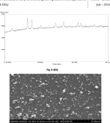
www.ijaera.org 2016, IJA-ERA - All Rights Reserved 164 iv) NANO ROD IRON OXIDE
From Fig 3.4 (a) UV- visible spectrum clearly shows that is γ-Fe2O3. (b) XRD showing peak position
at 350, 380, 580 are worth to notify.(c)SEM image showing nano rod of iron oxide nano-particles.
300 400 500 600
1.0 1.5 2.0
Abs
orbance (A)
Wavelength (nm) FeSO
4 0 10 20 30 40 50 60 70 80 90
-200 -100 0 100 200 300 400 500 600
Int
en
sity
2
Distorted FeO
500 1000 1500 2000 2500 3000 3500 4000 4500 0.975
0.980 0.985 0.990 0.995 1.000 1.005
% Tra
nsm
ittan
ce
Wavenumber (cm-1
)
Distorted Fe3O4
0.8 1.6 2.4
Abs
orbance (A)
Wavelength (nm) -FeCl
3 [A]
Fig 3.3 (a) Fig 3.3
(b)
Fig
3.3(c) Fig 3.3(d)
www.ijaera.org 2016, IJA-ERA - All Rights Reserved 165 v) EXPERIMENTAL INVESTIGATION
To check the thermal enchancement properties of nano-particles the nano fluid is made to run in counter flow concentric tube heat exchanger and inlet and outlet temprature of hot fluid and cooling fluids i.e water and different nanofluids were noted down in tabular form.Concentration of different nano-particles is same in base fluid.
T1= Hot water inlet temp., T2= Cold water outlet temp., T3= Hot water outlet temp., T4= cold water
inlet temp.
LMTD= ѳ1- ѳ2/ln(ѳ1/ ѳ2) → (1)
ѳ1 = T1-T2 &ѳ2 = T3-T4 →(2)
Fig 3.4(b)
www.ijaera.org 2016, IJA-ERA - All Rights Reserved 166
TABLE:I
Fluid T1,0c T2, 0c T3, 0c T4, 0c LMTD
Water 90 79.19 40.23 25 12.894
Iron oxide cubic nanofluid 90 72.68 37.48 25 14.768
Iron oxide destorted nanofluid 90 73.12 36.89 25 14.215
Iron oxide nano-rod nanofluid 90 72.76 37.12 25 14.529
Cobalt oxide nanofluid 90 70.59 35.24 25 14.339
III. CONCLUSION
Using solvo thermal process high quality nano-particles can be formed that is shown by the different characterisation is done on nano-particles.From the table I, it is clearly cocluded that heat carrying capacity of nanofluid is large than the base fluid.Though different shape of nano particles have less impact , heat carrying capacity nearly same for different shape iron oxide nanofluids. Cobalt oxide significantly improve the heat carrying capacity of base fluid which is water in this case.So cobalt oxide can also be used as nanofluid for heat transfer enhancement.
Conflict of Interest: The authors declare that they have no conflict of interest.
Ethical Statement: The authors declare that they have followed ethical responsibilities.
REFERENCES
[1] Zhang, Y., W. Jiang, and L. Wang, Microfluidic synthesis of copper nanofluids. Microfluidics and nanofluidics, 2010. 9(4-5): p. 727-735.
[2] Radhakrishnan, A.A. and B.B. Beena, Structural and Optical Absorptio n Analysis of CuO Nanoparticles. Indian Journal of Advances in Chemica l Science, 2014. 2: p. 158-161.
[3] Sun, Y. and Y. Xia, Shape-controlled synthesis of gold and silver nanoparticles. Science, 2002. 298(5601), pp. 2176-2179.
[4] Yang, Y., et al., Solvothermal synthesis of multiple shapes of silver nanoparticles and their SERS properties. The Journal of Physical Chemistry C, 2007. 111(26): p. 9095-9104.
[5] Rashin, M.N. and J. Hemalatha, A novel ultrasonic approach to determine thermal conductivity in CuO– ethylene glycol nanofluids. Journal of Molecular Liquids, 2014. 197: p. 257-262.
[6] Manigandan, R., et al., Cobalt oxide nanoparticles: characterization and its electrocatalytic activity towards nitrobenzene. Chem. Sci. Trans., 2013. 2: p. S47-S50.
[7] Yu, W. and H. Xie, A review on nanofluids: preparation, stability mechanisms, and applications. Journal of Nanomaterials, 2012. 2012: p. 1.
[8] Cheon, J., et al., Shape evolution of single-crystalline iron oxide nanocrystals. Journal of the American Chemical Society, 2004. 126(7): p. 1950-1951.
[9] Jana, N.R., Y. Chen, and X. Peng, Size-and shape-controlled magnetic (Cr, Mn, Fe, Co, Ni) oxide nanocrystals via a simple and general approach. Chemistry of materials, 2004. 16(20): p. 3931-3935. [10] Sun, S. and H. Zeng, Size-controlled synthesis of magnetite nanoparticles. Journal of the American
Chemical Society, 2002. 124(28): p. 8204-8205.
[11] Eastman, J., et al. Enhanced thermal conductivity through the development of nanofluids. in MRS proceedings. 1996. Cambridge Univ Press.
www.ijaera.org 2016, IJA-ERA - All Rights Reserved 167
[13] Herrero, M., et al., Nanosize cobalt oxide-containing catalysts obtained through microwave-assisted methods. Catalysis Today, 2007. 128(3): p. 129-137.
[14] Makhlouf, M.T., B. Abu-Zied, and T. Mansoure, Nanocrystalline Co3O4 fabricated via the combustion method. Metals and Materials International, 2013. 19(3): p. 489-495.
[15] Sun, S., et al., Monodisperse MFe2O4 (M= Fe, Co, Mn) nanoparticles. Journal of the American Chemical Society, 2004. 126(1): p. 273-279.
[16] Kang, Y.S., et al., Synthesis and characterization of nanometer-size Fe3O4 and γ-Fe2O3 particles. Chemistry of Materials, 1996. 8(9): p. 2209-2211.
[17] Wu, W., et al., Large-scale and controlled synthesis of iron oxide magnetic short nanotubes: shape evolution, growth mechanism, and magnetic properties. The Journal of Physical Chemistry C, 2010. 114(39): p. 16092-16103.