D 14 MECHANICAL ENGINEERING: Dynamics and Strength of Machines JOURNAL OF ENGINEERING SCIENCES
ЖУРНАЛ ІНЖЕНЕРНИХ НАУК
ЖУРНАЛ ИНЖЕНЕРНЫХ НАУК
Web site: http://jes.sumdu.edu.ua DOI: 10.21272/jes.2019.6(2).d3 Volume 6, Issue 2 (2019)
Ensuring the Vibration Reliability of Rotors Connected by Spline Joints
Verbovyi A.1*, Neamtu C.2, Sieryk, M.1, Vashyst B.1, Pavlenko V.3, Simonovskiy V.1, Pavlenko, I.11 Sumy State University, 2 Rymskogo-Korsakova St., 40007 Sumy, Ukraine;
2 Technical University of Cluj-Napoca, 28 Memorandumului St., 400114 Cluj-Napoca, Romania;
3 Machine Building College of Sumy State University, 17 T. Shevchenka Ave., 40000 Sumy, Ukraine
Article info: Paper received:
The final version of the paper received: Paper accepted online:
August 17, 2019 December 5, 2019 December 10, 2019
*Corresponding Author’s Address:
[email protected]
Abstract. This article is devoted to the development of refined numerical mathematical models of rotor dynamics
of high-performance turbomachines having a spline connection. These models consider the dependence of the critical frequencies of the shaft on the angular stiffness of the spline connection, as well as the procedure of virtual balancing. As a result of the complex application of this approach, the methods of calculation of vibration characteristics taking into ac-count variable values of angular rigidity of splined connection are offered. In addition, the method of evaluat-ing the system of initial imbalances with the correspondevaluat-ing displacements of the rotor axis in the correction and cal-culation sections has also been improved. The proposed approaches, based on the integrated application of CAE software and computational intelligent systems, allow for modal and harmonic analysis and implement virtual balanc-ing with a significant reduction in preparation and machine time without loss of relative accuracy. In addition, the de-veloped mathematical model of free and forced vibrations of rotor systems have been implemented in the program code operational files “Critical Frequencies of the Rotor” and “Forced Oscillations of the Rotor” of the computer al-gebra system MathCAD that allows improving the dynamic balancing procedure for evaluating primary imbalances. The high accuracy of the proposed approach is confirmed by checking the dynamic deviations of the rotor axis by the system of residual imbalances in accordance with the standards of vibration stability.
Keywords: turbomachine, spline connection, angular stiffness, virtual balancing, modal analysis, harmonic analysis.
1
Introduction
Nowadays, due to the increasing demand for the use of such power equipment as rotary machines, in particular, turbo-pump turbochargers and units, the question of their vibration reliability become more and more urgent. The main source of vibration of any pump unit is an unbal-anced rotor. But in addition to an unbalunbal-anced rotor, there are also many other factors that create in their totality a complex effect on the vibrational state of the unit. This can be the body stiffness, stiffness of the bearing seals and various types, the compression ratio of the axial ro-tor, the type and technical condition of the connection of the rotors of the unit and the engine, and others. One type of shaft connection with the engine is a connection that wears out with the operation process and, as a conse-quence, loses angular stiffness.
The article is devoted to the study of the influence on the vibration state of turbopump units with angular stiff-ness of splined joints based on the finite element method with the use authors’ files “Critical frequencies of the rotor” and “Forced oscillations of the rotor” of the com-puter algebra system Mathcad.
2
Literature Review
The problem posed above can be solved after the study of special scientific literature on the topic of extreme research in computer modeling of rotor dynamics. For example, in work [1] dynamics of rotor systems of tur-bopump units with the present splined connection, and also the calculation of vibrational characteristics of a rotor taking into account its preliminary axial preload is considered. The research work [2] is devoted to methods of research of dynamics of a rotor on ball bearings with the combined application of spatial and beam settlement models. In the research work [3], the influence of differ-ent classes of bearings on vibrations is considered.
Journal of Engineering Sciences, Volume 6, Issue 2 (2019), pp. D 14–D 19 D 15
3
Research Methodology
3.1
Evaluation of eigenfrequencies
The object of the study was the shaft line of a liquid-propellant engine, which consists of an oxidizer rotor and a fuel pump rotor connected to each other by means of a splined connection. During the operation of the unit, the phenomenon of wear of the slots is inevitable, as a result of which the angular stiffness of this connection changes, which in turn leads to corresponding changes in the natu-ral frequency spectrum.
The computer program “Critical Frequencies of the Rotor”, which is based on the finite element method, allows determining the natural frequencies of the shaft, the scheme of which is presented in Figure 1.
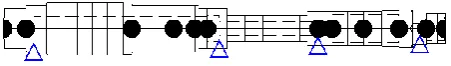
Figure 1 – The design scheme of the rotor
To further study the dynamics of the rotor, it is neces-sary to create a computational model. In the program “Critical frequencies of the rotor” was created beam finite element model (Figure 2).
Figure 2 – The finite element model of the rotor dynamics with spline joint using the file “Critical Frequencies of the Rotor”
In this paper, the critical frequencies of the shaft line are for two variants: "Hinge" and "Rigid connection". For the first option, the values of the stiffness of the bearings were taken the minimum, wherein the spline connection for the shafts was taken hinged. For the second option, the maximum stiffness for the bearings was adopted, and the splined connection was taken according to the scheme of rigid fastening. The connection of both parts of the rotors in the shaft through the slot forms a weak dynamic connection between them.
3.2
Simulation of forced oscillations
The program “Forced oscillations of the rotor”, allows one to calculate the forced oscillations of the rotor at a given speed of rotation under the influence of certain imbalances. The result of the calculation is the amplitude and shape of the rotor deflection when operating at a certain operating frequency.
Figure 3 – The finite element model of the rotor dynamics with a splined joint for calculation of forced oscillations using
the file “Forced Oscillations of the Rotor”
The calculation of forced oscillations in the program is performed using the already known beam finite element model and the same mathematical algorithms that are laid down to solve the problems of finding eigenfrequencies and critical frequencies, but the right side of the matrix equation when-van rotating rotor, divided into finite ele-ments of the beam type-other than zero:
, (1)
where – column-vector of the eccentricity of the un-balanced local masses; Md – column-vector of the
unbal-anced local masses; ω – operating frequency.
To solve the problem of forced oscillations requires data such as density and modulus of elasticity of the ma-terial, the length of each section, external and internal diameter sections, mass details, support stiffness, the working speed of the rotor, the modulus and phase of point imbalances.
Theoretically, the unbalance of a flexible rotor is char-acterized by a certain spatial continuous curve, which is a hodograph of a continuous set of imbalance vectors nor-mal to the rotor axis. Therefore, since this method of setting is quite time-consuming, then in further calcula-tions it is sufficient to limit the task to a finite number of point imbalances located in the planes of the impellers and in the plane of the wheel since these elements are the most influential on the overall imbalance.
All the calculations and mode shapes of forced oscilla-tions were performed using the MathCAD software.
3.3
The performance of the virtual rotor
balancing
Due to the above-mentioned results, the first critical frequency of the oxidizer’s rotor is close to the first criti-cal frequency of the turbopump unit and not significantly increased the maximum rotor speed. According to the practice of designing and exploitation of pumping units, this relatively small deviation from the resonance (about 10 %) determines the dynamic characteristics of a rotor as a flexible one. In this case, the rotary system needs bal-ancing both at operating and critical frequencies. Moreo-ver, the total number of correction planes should be not less than three.
D 16 MECHANICAL ENGINEERING: Dynamics and Strength of Machines any operating frequency must be equal
to zero. Therefore, for each measurement frequency can be written:
(2)
As a result, the system a linear equation with complex coefficients is achieved to determine l complex balancing weights . Dynamic complex weights are defined by the following equation:
, (3)
where a – number of points (a = 1, 2, …, k); i – initial number of measured points (i = 1, 2, ..., l); l – number of correction planes; – deflection at the measurement point a when setting the test imbalance in the correction plane i at the rotor speed – trial imbalance. The system of equations (3) can be rewritten in a matrix form:
, (4)
where –
the column vector of complex amplitudes, measured at
the “zero” start; – a column
vec-tor of the estimated complex balancing of masses; - a rectangular matrix of complex mass coefficients
The linear regression formula cannot be used directly to solve the matrix equation (4). It is necessary to form relations between the two vectors with the corresponding real and imaginary components. Vector and k of com-plex amplitudes correspond to the vector 2k real and im-aginary components :
. (5)
Accordingly, an elongated vector with 2l real and im-aginary imbalances can be introduced:
(6)
So, the matrix of mass coefficients can be presented in the following form:
, (7)
where the arbitrary coefficient of the matrix W is defined by the formula:
(8)
The complex matrix equation (4) corresponds to the real matrix equation:
(9)
where the columns of vectors Y and D are deter-mined by equations (5), (6). The linear regression for-mula can be implemented in the resulting equation (8). In this case, the system of imbalances D is estimated by the vector of measured displacements by the following formula:
(10)
If the balancing procedure is provided by the meas-ure at multiple frequencies , the vector
has size :
, (11)
and the elongated vector Y has size
(12)
The matrix W will be expanded n times vertically
and have size .
Each matrix is similar to the
ma-trix . To assess the system of imbalances
(13)
the balancing process is implemented by establish-ing a mass balancestablish-ing system in the planes of correction under the phase angles:
(14)
Journal of Engineering Sciences, Volume 6, Issue 2 (2019), pp. D 14–D 19 D 17
3.4
Assessment of the quality of rotor
balancing
Residual imbalances are estimated by the algorithms described above, namely by the formulas:
The equation of the dependence of the deflection am-plitudes on the imbalance is as follows:
, (15)
where – a column vector of the deflection ampli-tudes; – matrix of influence coefficients; – vector-column of estimated imbalances.
If we introduce the concept of the i-th vector of trial imbalances, as a certain set of imbalances consisting of a trial imbalance D set in the i-th plane of correction, then or the i-th start of the rotor (i = 1, 2, …, 8) you can write the equation:
(16)
or
, (17)
where D = 0.01 kg·m – the scalar value of trial imbal-ance; - identity matrix.
Subtracting (16) from (17), one can define a matrix of influence coefficients, each element of which is equal to
, (18)
where k = 8 – number of nodes with estimated imbal-ances; l = 8 – number of runs excluding zero.
The value of the trial imbalance is assumed D = 0.01 kg·m.
Amplitudes of deflections in correction planes 1, 3, 10, 11, 29–31, 36 as components of the column-vector .
4
Results
4.1
Critical frequencies of the rotor
In Table 1, data of calculations of critical frequencies of rotors and a shaft of the turbopump unit which have turned out by means of beam models result.
The lower and upper border corresponds to both “joint” and “solid shaft” connections. From the results of calculations, it can be seen that the first two critical fre-quencies of the rotor of the oxidizing turbopump are al-most the same as the first two critical frequencies of the continuous shaft line. Therefore, we see that the forms of free oscillations also coincide for the first and second.
Therefore, to assess the displacement of the rotor sys-tem of the turbopump unit from the resonant modes, it is possible to consider only the dynamics of the rotor to the oxidizer turbopump unit.
Table 1 – Critical frequencies of rotor systems found in the computer program “Critical Frequencies of the Rotor”, rad/s
System Number of critical frequency
1 2 3
Oxidizer 2623–3101 3251–6513 5429–10100
Fuel pump 3974-5270 5675-13420 7369-14310
Turbopump 2600–3363 3252–6211 3832–6615
4.2
Results of calculation of forced oscillations
of the shaft line
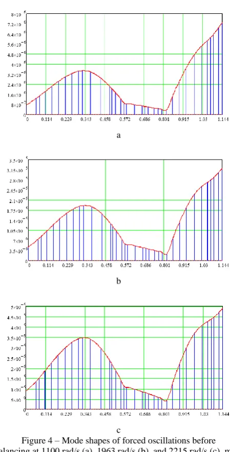
Calculations and forms of forced oscillations that are performed using the Mathcad program are presented be-low.
a
b
c
Figure 4 – Mode shapes of forced oscillations before balancing at 1100 rad/s (a), 1963 rad/s (b), and 2215 rad/s (c), m
4.3
Balancing quality assessment
D 18 MECHANICAL ENGINEERING: Dynamics and Strength of Machines
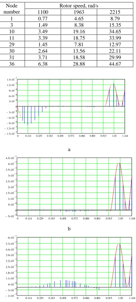
Table 2 – Deflections in the correction planes found in the computer program “Critical frequencies of the rotor”, µm
Node number
Rotor speed, rad/s
1100 1963 2215
1 0.77 4.65 8.79
3 1.49 8.38 15.35
10 3.49 19.16 34.65
11 3.39 18.75 33.99
29 1.45 7.81 12.97
30 2.64 13.56 22.11
31 3.71 18.58 29.99
36 6.38 28.88 44.67
Ôîðìà âèìóøåíèõ êîëèâàíü, ì:
0 0.114 0.229 0.343 0.458 0.572 0.686 0.801 0.915 1.03 1.144
1.5 − 10−7
1.2 − 10−7
9 −10−8
6 −10−8
3 −10−8
0 3 10 −8 6 10 −8 9 10 −8 1.2 10 −7 1.5 10 −7
a
Ôîðìà âèìóøåíèõ êîëèâàíü, ì:
0 0.114 0.229 0.343 0.458 0.572 0.686 0.801 0.915 1.03 1.144 5
− 10−8 0 5 10 −8 1 10 −7 1.5 10 −7 2 10 −7 2.5 10 −7 3 10 −7 3.5 10 −7 4 10 −7 4.5 10 −7
b
Ôîðìà âèìóøåíèõ êîëèâàíü, ì:
0 0.114 0.229 0.343 0.458 0.572 0.686 0.801 0.915 1.03 1.144 1
− 10−7 3 − 10−8
4 10 −8 1.1 10 −7 1.8 10 −7 2.5 10 −7 3.2 10 −7 3.9 10 −7 4.6 10 −7 5.3 10 −7 6 10 −7
Figure 5 – Mode shapes of forced oscillations after balancing at 1100 rad/s (a), 1963 rad/s (b), and 2215 rad/s (c), m
Hence, the maximum amplitude after balancing has been decreased by two orders.
5
Conclusions
As a result of the work, free and forced oscillations of the shaft pipeline for two variations “joint” and “solid shaft” were obtained. We considered the existing meth-ods of taking into account the stiffness of the splined joint at the critical frequencies of the rotor of the turbopump unit.
The Mathcad and ANSYS programs performed calcu-lations and obtained the results of the maximum permis-sible critical frequencies of the oxidizer rotor for the tur-bopump, the fuel pump rotor and for the solid shaft line.
The rotor of the oxidizer turbopump and the fuel pump is a rigid rotor design in fact, that the value of the maxi-mum operating frequency lies below the first critical frequency of both the entire shaft design and both rotors separately.
The values of the first critical frequency obtained from the calculation are 2600 rad/s (option “joint”) and 3363 rad/s (option “solid shaft”).
The next step was to obtain deflections in the nodes belonging to the correction planes in the initial state of the rotor. Determined that the maximum deflection is 45 µm, this result is unacceptable. Therefore, it is neces-sary to balance the rotor.
In order to reduce the vibration of the shaft, it was de-cided to conduct a virtual balancing of the rotor. The corresponding algorithm for calculating the vibration state of the rotor is implemented using the working file “Forced Oscillations of the Rotor” of the computer pro-gram MathCAD, followed by its improvement by a virtu-al bvirtu-alance to obtain results that meet the standards of GOST ISO 1940-1-2007 “Vibrations. Requirements to Quality of Balancing of Rigid rotors” and GOST ISO 11342-95 “Methods and Criteria of Balancing of Flexible Rotors”.
6
Acknowledgments
The results of the research were partially obtained as a part of the research work funded by the State Design Bureau “Yuzhnoye” (Ukraine). Additionally, the part of scientific results related to the computer modeling was obtained jointly by Sumy State University (Ukraine) and Technical University of Cluj-Napoca (Romania) within the international grant “Ensuring the Vibration Reliability of Numerical Methods and Studies of the Dynamics of Rotors of Centrifugal Machines” funded by EU Program Erasmus+, as well as a part of Ph.D. thesis of A. Verbovyi and B. Vashyst.
References
1. Pavlenko, I. V., Simonovskiy, V. I., Pitel’, J., Demianenko, M. (2018). Dynamic Analysis of Centrifugal Machines Rotors with
Combined Using 3D and 2D Finite Element Models. Sumy State University, Sumy, Ukraine.
2. Pavlenko, I. V., Simonovskiy, V. I., Demianenko, M. M. (2017). Dynamic analysis of centrifugal machines rotors supported on
ball bearings by combined application of 3D and beam finite element models. IOP Conference Series: Materials Science and
Journal of Engineering Sciences, Volume 6, Issue 2 (2019), pp. D 14–D 19 D 19
3. Yashchenko, A. S., Rudenko, A. A., Simonovskiy, V. I., Kozlov, O. M. (2017). Effect of bearing housings on centrifugal pump
rotor dynamics. IOP Conference Series: Materials Science and Engineering, Vol. 233(1), article number 012054, doi:
10.1088/1757-899X/233/1/012054.
4. Pavlenko, I., Ivanov, V., Kuric, I., Gusak, O., Liaposhchenko, O. (2019). Ensuring vibration reliability of turbopump units using
artificial neural networks. Advances in Manufacturing II - Volume 1. Lecture Notes in Mechanical Engineering. Springer, Cham,
pp. 165–175, 2019, doi: 10.1007/978-3-030-18715-6_14.
5. Pavlenko, I., Simonovskiy, V., Ivanov, V., Zajac, J., Pitel, J. (2019). Application of artificial neural network for identification of
bearing stiffness characteristics in rotor dynamics analysis. Advances in Design, Simulation and Manufacturing, DSMIE 2018,
Lecture Notes in Mechanical Engineering, Springer, pp. 325–335, doi: 10.1007/978-3-319-93587-4_34.
6. Ding, F., Wang, Z., Qin, F. (2015). Two kinds of neural network fusion of aero-engine rotor vibration signal fault diagnosis. 4th
International Conference on Mechatronics, Materials, Chemistry and Computer Engineering, pp. 1546–1552.
7. Tanoh, A., Konan, D. K., Koffi, M., Yeo, Z., Kouacou, M. A., Koffi, B. K., N’guessan, K. R. (2008). A neural network
applica-tion for diagnosis of the asynchronous machine. Journal of Applied Sciences, Vol. 8, pp. 3528–3531, doi:
10.3923/jas.2008.3528.3531.
8. Pavlenko, I., Neamtu, C., Verbovyi, A., Pitel, J., Ivanov, V., Pop, G. (2019). Using computer modeling and artificial neural
net-works for ensuring the vibration reliability of rotors. CEUR Workshop Proceedings, Vol. 2353, pp. 702–716.
9. Pavlenko, I., Trojanowska, J., Gusak, O., Ivanov, V., Pitel, J., Pavlenko, V. (2019). Estimation of the reliability of automatic
ax-ial-balancing devices for multistage centrifugal pumps. Periodica Polytechnica Mechanical Engineering, Vol. 63(1), pp. 277–
281, doi: 10.3311/PPme.12801.
10. Kim, Y. W., Jeong, W. B. (2018). Reliability evaluation technique of compressor using pressure pulsation and vibration signals.
Journal of Physics: Conference Series, Vol. 1075, article number 012076, doi: 10.1088/1742-6596/1075/1/012076.
11. Ben Rahmoune, M., Hafaifa, A., Guemana, M. (2015). Neural network monitoring system used for the frequency vibration
pre-diction in gas turbine. 3rd International Conference on Control, Engineering and Information Technology, article number
15418537, doi: 10.1109/CEIT.2015.7233185.
12. Pavlenko, I., Trojanowska, J., Ivanov, V., Liaposhchenko, O.: Scientific and methodological approach for the identification of
mathematical models of mechanical systems by using artificial neural networks. 3rd Conference on Innovation, Engineering and
Entrepreneurship, Regional HELIX 2018, Lecture Notes in Electrical Engineering, Springer, Vol. 505, pp. 299–306, doi: 10.1007/978-3-319-91334-6_41.
13. Manjurul, M. M., Kim, I.-M. (2018). Motor bearing fault diagnosis using deep convolutional neural networks with 2D analysis
of vibration signal. Lecture Notes in Computer Science, Vol. 10832, pp. 144–155, doi: 10.1007/978-3-319-89656-4_12.
УДК 621.671:534.1
Підвищення вібраційної надійності роторів, з’єднаних шліцьовим з’єднанням
Вербовий А. Є.1, Неамцу К.2, Сєрик М. Л.1, Вашист Б. В.1, Павленко В. В.3, Симоновський В. І.1, Павленко І. В.11 Сумський державний університет, вул. Римського-Корсакова, 2, 40007, м. Суми, Україна;
2 Технічний університет міста м. Клуж-Напока, вул. Меморандума 28, 400114, м. Клуж-Напока, Румунія;
2 Машинобудівний коледж СумДУ, просп. Т. Шевченка, 17, 40000, м. Суми, Україна
Анотація. Стаття присвячена розробленню уточнених математичних моделей динаміки роторних систем
енергоємних турбомашин, що мають шліцьове з’єднання, та числових методів дослідження їх вільних і вимушених коливань. Запропоновані моделі враховують залежності критичних частот валопровода від кутової жорсткості шліцьового з’єднання, а також реалізують процедуру його віртуального балансування. У результаті комплексного застосування такого підходу запропоновано методи розрахунку вібраційних характеристик турбомашин з урахуванням можливої зміни кутової жорсткості шліцьового з’єднання. Крім цього, було вдосконалено методику оцінювання системи початкових дисбалансів за даними зміщень осі ротора у площинах колекції та розрахункових площинах. Запропоновані підходи, засновані на комплексному застосуванні програмного забезпечення на основі методу скінченних елементів та обчислювальних інтелектуальних систем, дозволяють проводити модальний і гармонічний аналіз та реалізовувати віртуальне балансування зі значним зменшенням підготовчого і машинного часу без втрати відносної точності. Крім того, розроблені математичні моделі вільних і вимушених коливань роторних систем були реалізовані у вигляді програмних кодів робочих файлів “Critical Frequencies of the Rotor” та “Forced Oscillations of the Ro-tor” системи комп’ютерної алгебри MathCAD, що дозволяє удосконалити процедуру динамічного балансування для оцінкювання системи початкових дисбалансів. Висока точність запропонованого підходу підтверджується перевіркою динамічних відхилень осі ротора у результаті дії системи залишкових дисбалансів відповідно до міжнародних стандартів вібраційної надійності.
Ключові слова: турбомашина, шліцьове з’єднання, кутова жорсткість, віртуальне балансування, модальний