IJEDR1904066 International Journal of Engineering Development and Research (www.ijedr.org) 377
An Analysis of Conceptual Aircraft Design Using
CFD
1K.Srinivasa Reddy, 2Dr.M.Mahesh 1P.G Scholar, 2Associate Professor
Guntur Engineering College
_____________________________________________________________________________________________________
Abstract - The evaluation of how Computational Fluid Dynamics (CFD) package may be incorporated into a conceptual design method is performed. The repeatability of the CFD solution as well as the accuracy of the calculated aerodynamic coefficients and pressure distributions was also evaluated on two different wing-body models. The overall run times of three different mesh densities was also evaluated to investigate if the mesh density could be reduced enough so that the computational stage of the CFD cycle may become affordable to use in the conceptual design stage. A farfield method was derived and used in this analysis to calculate the lift and drag coefficients. The CFD solutions were also compared with two methods currently used in conceptual design - the vortex lattice based program Vorview and ACSYNT. The unstructured Euler based CFD package FELISA was used in this study.
keywords - CFD, Analysis of Air Craft, CFD Analysis, Air Craft Design.
_____________________________________________________________________________________________________
I.INTRODUCTION
Aircraft design begins with the conceptual phase, where possible designs are first imagined and evaluated from initial design requirements. In this phase, the designer has the greatest flexibility in determining the layout and configuration of the aircraft. After the conceptual phase, however, only minor changes to the aircraft configuration may occur. Therefore, it is important to have accurate drag and lift predictions early in the design phase when major configuration changes can occur. The accuracy of these predictions must be balanced, however, with calculation speed. This is needed so many types of configurations can be compared and so size optimization on a selected configuration may occur. Aerodynamics for conceptual designs is typically based on linear aerodynamic theory, supplemented with empirical data. These methods work well for subsonic flows, where nonlinearities in the flow are negligible, but break down when the nonlinearities become important. For flows that are entirely supersonic there are nonlinear methods that work well for aerodynamic predictions. However, for transonic flows these methods fail because the flow has both subsonic and supersonic areas. The desire for more accurate lift and drag prediction for transonic flows - along with a more detailed analysis of the flow field for all flows types - have resulted in the increased use of computational fluid dynamics (CFD) early in the design stage.
The purpose of this work is to evaluate how an unstructured Euler CFD package may be incorporated into a conceptual design method. The repeatability of the CFD solution as well as the accuracy of the calculated aerodynamic coefficients and pressure distributions will be evaluated. The overall run times of three different mesh densities will also be evaluated. If the density of the mesh is reduced enough, the computational stage of the CFD cycle may become affordable to use in the conceptual design phase, but this must be balanced with the solution accuracy. The unstructured Euler based CFD package FELISA was used in this study.
II.METHODOLOGY A. The FELISA System
FELISA is an unstructured CFD surface and volume mesh generator with a finite element method (FEM) Euler based flow solver. It was created for NASA by J. Perio of Imperial College, J. Peraire of M.I.T. and K. Morgan of University College of Swansea. or this analysis version 2.0 Beta of FELISA was used on a Silicon Graphics Octane workstation running IRIX 6.5.13 with a 195 MHz R10000 processor and 640 MB of RAM. This SGI Octane has a SPECfp95 rating (which is a measure of the speed the
CPU can perform floating point operations) of 17.0. This would convert to an approximate SPECfp2000 rating of 140. It is predicted that the Apple G5 running a 1.6 GHz processor (available in the fall of 2002) will have a SPECfp2000 rating of around
1400. Therefore, the CPU run times given for the SGI in this analysis would be approximately 10 times faster if the analysis was run on the G5. Starting from a file (.dat) which contains the surface points and surface intersection curves of a CAD model and a file (.bac) which contains the source distribution, the surface triangle mesh is generated by a two dimensional advancing front
IJEDR1904066 International Journal of Engineering Development and Research (www.ijedr.org) 378 must supply a file (.bco) with the boundary type of each surface. A control file (.nam) is also used to provide the different algorithmic constraints (CFL number, number of time steps, Mach number, angle of attack, etc.).
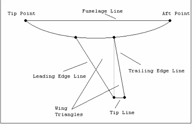
Fig 1: Wing Body
Three mesh densities were evaluated on the two different wing-body models. Each mesh density was created and run three separate times for each model to ensure the repeatability of the solution. The lift and drag (initially by surface integration but a farfield method is also used), as well as the pressure coefficient at selected wing stations, were compared with the other mesh densities and the experimental values reported in AGARD AR-303. The wall time and the CPU time where recorded for the total CFD cycle - the surface mesh generation, the volume mesh generation and the flow solution. Also, the lift and drag were compared with the results from two different methods currently used in conceptual design - Vorview (a vortex lattice method) and ACSYNT. The parameters for the source spacing of the three mesh densities used in this analysis are
shown in Tables 1 - 3.
Table 1 Mesh 1 Parameters
Xc D
Far Field 50% Fuse. Length -- --
Fuse. Point 0.8% Fuse. Length 2.4% Fuse. Length 8% Fuse. Length
Fuse. Line 1.5% Fuse. Length Fuse. Radius 4 * Fuse. Radius
Wing Line 3.0% Wing MAC 6% Wing MAC 24% Wing MAC
Wing Triangle 5.0% Wing MAC 10% Wing MAC 40% Wing MAC
Table 2 Mesh 2 Parameters
Xc D
Far Field 45% Fuse. Length -- --
Fuse. Point 0.7% Fuse. Length 2.4% Fuse. Length 8% Fuse. Length
Fuse. Line 1.2% Fuse. Length Fuse. Radius 4 * Fuse. Radius
Wing Line 2.5% Wing MAC 6% Wing MAC 24% Wing MAC
Wing Triangle 4.2% Wing MAC 10% Wing MAC 40% Wing MAC
Table 3 Mesh 3 Parameters
Xc D
Far Field 40% Fuse. Length -- --
Fuse. Point 0.6% Fuse. Length 2.4% Fuse. Length 8% Fuse. Length
Fuse. Line 1.0% Fuse. Length Fuse. Radius 4 * Fuse. Radius
Wing Line 2.0% Wing MAC 6% Wing MAC 24% Wing MAC
Wing Triangle 3.5% Wing MAC 10% Wing MAC 40% Wing MAC
IJEDR1904066 International Journal of Engineering Development and Research (www.ijedr.org) 379 to complete on the same SGI machine used in the CFD analysis. The input file for ACSYNT defines the geometry, weights and propulsion system of the aircraft. Also, user entered aerodynamic parameters are used in the minimum drag calculation - which includes the frictional, wave and interference drags. For this analysis, the aerodynamic parameters were left to their default values - except the wing type, which was set to the supercritical (transonic) wing - and all values which could be estimated from the geometric inputs were calculated by ACSYNT. A detailed aerodynamic analysis was done at the specified Mach number and angle of attack for each wing-body. The geometry was set by defining the geometric parameters such as wing aspect ratio and taper ratio and the fuselage length and diameter. The geometry can be further manipulated through a graphical user interface. The runs took approximately 30 seconds
III.MESHING OF WING
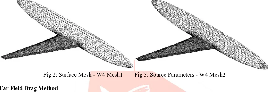
The W4 and M165 wing-bodies were run three different times on three different meshes. The W4 wing-body was analyzed at a freestream Mach number of 0.78 and an angle of attack of 1.52º. The M165 wing-body was analyzed at a freestream Mach number of 0.90 and an angle of attack of 4.99 º. The results presented in this chapter are for the first run on each of the meshes. The two other runs produced the same values for the points, triangles and tetrahedral in the surface and volume meshes. CPU run times for the mesh generation were equal to the first run within three significant digits and within two significant digits for the flow solutions.
Fig 2: Surface Mesh - W4 Mesh1 Fig 3: Source Parameters - W4 Mesh2
A. Far Field Drag Method
The standard technique in evaluating the lift and drag coefficients from an Euler CFD solution is to integrated the pressure on the surface. This method does not work for calculating the drag coefficients (all but one drag value was negative). This error occurs because the aircraft surface is represented by triangles; therefore high grid resolution must be used in order to accurately represent curved surfaces. Also, errors are introduced from the subtraction of two large forces in the flow direction. Therefore, the pressure distribution must be accurately known in order to determine the drag force. These two problems suggest that in order for a surface
integration technique to be accurate, a fine computational grid must be used, resulting in long run times. Another problem with surface integration technique is that they combine different drag components into one resultant drag coefficient. It is important, especially in conceptual design, to know how the drag is being produced so the aircraft can be efficiently designed. These limitations of the surface integration technique have led researchers to look at other methods to evaluate the lift and drag coefficients generated by CFD. One method is the Wake Integration technique. In this method, the drag is computed from the physical phenomenon that causes drag forces. This is done by evaluating the vortex and entropy produced on a plane perpendicular to the flow which lies downstream from the aircraft. The vortices produced are results of the lift induced drag, and the entropy production is related to the wave drag. Thus, this method will be used in this analysis since it is not as dependent on the grid resolution as surface integration, and it separates the drag components by the physical phenomena that create the drag.
1. Lift & Drag
The value for the lift coefficient calculated by surface pressure integration wasnalso compared among the different runs. Table.4: Surface Integration Lift Repeatability - W4
Run1 Run2 Run3
Mesh1 0.6952 0.6952 0.6952
Mesh2 0.7136 0.7136 0.7136
Mesh3 0.7266 0.7265 0.7265
Table.5: Surface Integration Lift Repeatability - W165
Run1 Run2 Run3
Mesh1 0.3551 0.3551 0.3551
Mesh2 0.3616 0.3616 0.3616
Mesh3 0.3655 0.3655 0.3655
IV.RESULTS AND DISCUSSIONS
IJEDR1904066 International Journal of Engineering Development and Research (www.ijedr.org) 380 lift coefficient agreement and the worst total drag coefficient agreement. Mesh3 had the longest solution time, the worst lift coefficient agreement and the best drag coefficient agreement. Mesh2 was in the middle for each of these results. Overall the S.I. technique produced better results for the lift coefficient, but the drag coefficients were significantly under predicted. The F.F.
technique produced better results for the drag coefficient and the lift coefficient was slightly higher than the S.I. value. Table.6: Overall Results - W4
CPU Solution Time - cv3
S.I. Lift %Diff.
F.F. Lift %Diff.
S.I. Drag %Diff.
F.F. Drag %Diff.
Mesh1 2:07 (2:20) 11.6% 13.1% -113% 23.0%
Mesh2 4:41 (5:11) 14.5% 15.1% -105% 10.7%
Mesh3 10:51 (12:06) 16.6% 17.4% -97.8% 4.04%
Overall Result Comparison
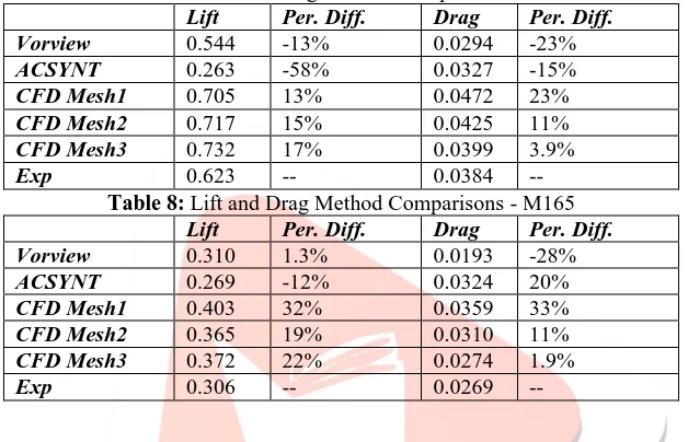
The results from the Vorview and ACSYNT analysis - along with the experimental and farfield CFD results Table 7: Lift and Drag Method Comparisons - W4
Lift Per. Diff. Drag Per. Diff.
Vorview 0.544 -13% 0.0294 -23%
ACSYNT 0.263 -58% 0.0327 -15%
CFD Mesh1 0.705 13% 0.0472 23%
CFD Mesh2 0.717 15% 0.0425 11%
CFD Mesh3 0.732 17% 0.0399 3.9%
Exp 0.623 -- 0.0384 --
Table 8: Lift and Drag Method Comparisons - M165
Lift Per. Diff. Drag Per. Diff.
Vorview 0.310 1.3% 0.0193 -28%
ACSYNT 0.269 -12% 0.0324 20%
CFD Mesh1 0.403 32% 0.0359 33%
CFD Mesh2 0.365 19% 0.0310 11%
CFD Mesh3 0.372 22% 0.0274 1.9%
Exp 0.306 -- 0.0269 --
V.CONCLUSION
For conceptual design an unstructured Euler based CFD system appears to be the best method. Using an unstructured mesh will allow non-experts to quickly generate a mesh around complex aircraft geometry. Using the Euler equations resulted in quick results - mesh generation and flow solution - since there was no need for the boundary layer. The complexity of the system was also reduced since there was no need for a turbulence model. It was found that all of the Euler CFD solutions were repeatable and the surface pressures of the CFD solution did produce similar trends compared to the experimental data. The deviations of the CFD surface pressures from the experimental data were primarily caused from the lack of the shock/boundary layer interaction in the Euler computations.
This resulted in the CFD solution having a sharper, less diffuse pressure distribution at the shock. It was also found that the surface integration technique did not produce acceptable results for the drag prediction. A farfield method was therefore derived to predict the aerodynamic coefficients. This method produced better results than the surface integration technique for the drag, but was sensitive to the artificial viscosity added (for stability) to the CFD solution. However, it must be noted that the farfield equations do not give any information on the pitching moment, which is needed in conceptual design. Reducing the number of points in the mesh significantly reduced the time needed to run the entire CFD solution. The Mesh1 solutions for both wing -bodies were completed five times faster than the Mesh3 solutions. The main problem with using the coarser mesh was the larger amount of entropy drag that was produced. Therefore, Mesh3 should be used in order to obtain reasonable drag predictions. For lift prediction, however, it was found that the coarser meshes produced better results. This was attributed to the shock being diffuse by the mesh spacing in the CFD solution, which simulated the boundary layer diffusing the shock in the experimental results.
REFERENCES
[1] Chao, D. D., and van Dam, C. P., "Airfoil Prediction and Decomposition," AIAA Paper 98-2783.
[2] Giles, Michael B. and Cummings, Russell M., "Wake Integration for Three- Dimensional Computations: Theoretical Developments," Journal of Aircraft, Vol. 36, No. 2, 1996, pp. 357-365.
[3] van Dam, C. P., Nikfetrat, K., Wong, K., and Vijgen, P. M. H. W., "Drag Prediction at Subsonic and Transonic Speeds Using Euler Methods," Journal of Aircraft, Vol. 32, No. 4, pp. 839-845.
[4] Hunt, David L., Cummings, Russell M. and Giles, Michael B., "Determination of Drag from Three-Dimensional Viscous and Inviscid Flowfield Computations," AIAA Paper 97-2257, June 1997.
[5] Maskell, E. C., "Progress Towards a Method for the Measurement of the Components of the Drag of a Wing of Finite Span," Royal Aircraft Establishment, TR 72232, Jan. 1973.
IJEDR1904066 International Journal of Engineering Development and Research (www.ijedr.org) 381 [7] Masson, Christian, and Veilleux, Charles, "Drag Prediction Using Euler Solutions of 2D and 3D Transonic Flows," AIAA Paper 99-16407, Jan. 1999.
[8] Fulker, J. L., "Pressure Distributions on Research Wing W4 Mounted on an Axisymmetric Body," AGARD AR 303, Case B3, 1994.
[9] Peiro, J., Peraire, J., and Morgan, K., "FELISA System: Version 1.1 Reference Manual," August 1994.
[10] Tannehill, John C., Anderson, Dale A., and Pletcher, Richard H. Computational Fluid Mechanics and Heat Transfer, 2nd ed., Taylor & Francis, Washington, D.C., 1997.
[11] Lessard, Wendy B., "Subsonic Analysis of 0.04-Scale F-16XL Models Using an Unstructured Euler Code," NASA TP-3597, Oct. 1996. 67
[12] Michal, Todd R., "Euler Technology Assesment for Preliminary Aircraft Design - Unstructured / Structured Grid NASTD Application for Aerodynamics of an Advanced Fighter / Tailless Configuration," NASA CR-1998-206947, Mar. 1998.
[13] Frink, Neal T., Pirzadeh, Shahyar and Parikh, Paresh, "An Unstructured-Grid Software System for Solving Complex Aerodynamic Problems," NASA CP-3291, May 1995.
[14] Frink, N.T. and Pirzadeh, S.Z., "Tetrahedral Finite-Volume Solutions to the Navier-Stokes Equations on Complex Configurations," Jan. 1998.
[15] Mason, William H., Knill, Duane L., Giunta, Antony A., Grossman, Bernard, Watson, Layne T., and Haftka, Raphael T., "Getting the Full Benefits of CFD in Conceptual Design," AIAA 98-2513, June 1998.
[16] Nixon, David, "Conceptual Design Method for Wings at Transonic Speeds," AIAA 97-2241, June 1997.
[17] Raj, P. "Aircraft Design in the 21st Century: Implications for Design Methods (Invited)," AIAA 98-2895, June 1998. [18] Ladeinde, Foluso, "Truley Automatic CFD Mesh Generation with Support for Reverse Engineering," AIAA 99-0828, Jan. 1999.
[19] Samareh-Abolhassani, Jamshid, "GridTool: A Surface Modeling and Grid Generation Tool," NASA CP-3291, 1995. [20] Gribben, B. J., Badcock, K. J., and Richards, B. E., "Towards Automatic Multiblock Topology Generation," AIAA 99 -3299, Nov. 1999.
[21] Stanniland, D. "Investigation of the Development on a Highly Swept Canard/Wing Research Model with Segmented Leading - and Trailing - Edge Flaps," AGARD 303, Case D5, 1994.
[22] Gloudemans, James R., Davis, Paul C. and Gelhausen, Paul A., "A Rapid Geometry Modeler for Conceptual Aircraft," AIAA 96-0052, Jan. 1996.
[23] Newsome, R. W. and Kandil, O. A., "Vortical Flow Aerodynamics - Physical Aspects and Numerical Simulation," AIAA 87-0205, Jan. 1987.