IJEDR1702188
International Journal of Engineering Development and Research (www.ijedr.org)1130
A PREDICTIVE CONTROL WITH DUAL INPUT AND DUAL
OUTPUT INDIRECT MATRIX CONVERTER
1
SANDEEP KUMAR,
2Er. DHARMENDRA SINGH
1SHEPHERD INSTITUTE OF ENGINEERING AND TECHNOLOGY, (SHUATS) ALLAHABAD
2SAM HIGGINBOTTOM UNIVERSITY OF AGRICULTURE, TECHNOLOGY AND SCIENCES
Abstract: Based on the traditional indirect matrix converter topology dual input dual output indirect matrix converter is proposed, but the conventional sixswitch inverter, used in the single output indirect matrix converter, is replaced by a nine -switch dual output converter. The matrix converter has several advantages over traditional rectifier-inverter type power frequency converters. It provides sinusoidal input and output waveforms, with minimal higher order harmonics and no sub harmonics. Model Predictive Control (MPC) uses the discrete -time model of the system to predict future value of the controlled variable for all possible control actions and user-defined cost function related to control objectives is solved to find its minimum. The matrix converter providing directly AC-AC power conversion is one of the most interesting members of the power converter family. The control action which minimizes the cost function is selected and applied to the system for the next time interval. This paper presents a finite control set model predictive control strategy for a dual-input dual-output indirect matrix converter.
I. INTRODUCTION
The dual input matrix converter is a converter, that consists of two input AC sources, nine voltage source converters (NVSC), Cu rrent source inverter, and Diode and foil capacitor. The matrix converter can be classified into two types and it depends upon the semiconducting stage. They are: 1) Indirect Dual matrix converter; 2) Direct Dua l matrix converter. The Indirect Direct Matrix Converter (IM C) is the two-stage ac-ac power converter and it can convert ac source to ac load without a dc-link capacitor or other storage components. This significantly improves overall system reliab ility by
eliminating fa ilure-prone dc-link e lectrolytic
capacitor. Dual output indirect matrix converter is based on the traditional IMC topology but the conventional six-switch inverter is replaced by a nine-switch inverter. This topology can produce two sets of three phase ac loads since nine switch inverter is a dual output inverter. Many matrix converter topologies have been proposed, mostly of the single-output type. In many applications, like e lectric traction and elevators, two or more ac loads need to be controlled independently. Single output type matrix converters can be used, but mult iple converter - one for each output - are required. An alternative is to use mult i-output matrix converter, with saving in terms of total nu mber of switches .
The dual-output indirect matrix converter, shown in Fig. 1, uses four-quadrant switches in Current Source Rect ifier (CSR) stage and has no dc-lin k capacitor. The rect ifier stage is connected to the Nine-Switch Inverter (NSI) stage.
Figure 1. Dual-Output Indirect Matrix Converter Topology
Fin ite States Model Predictive Control (FS-MPC) is an optimization based control approach that minimizes a cost function to optimize system behavior. This paper presents an application of predictive control in indirect matrix converters. The switching state is selected by minimizing a quality function that considers the instantaneous reactive power in the input, the current error in the output, and the generation of a positive voltage in the dc link. MPC uses discrete-time mode l of the power converters to predict the future behavior of the control variables and solves a cost function to determine optimu m control action. The control action that minimizes the cost function is selected and applied to the system for the next time interval. Diffe rent control objectives can be introduced in the cost function and controlled simu ltaneously by solving a single multi-objective cost function.
Imple mentation of model predict ive control
technique is easy. In this paper, a model predictive control scheme is proposed for dual-output indirect matrix converter. Different control objectives, like output load current control and minimizat ion of the instantaneous reactive power, are considered and performance of MPC is investigated.
II. S YSTEM MODEL
The rectifier stage includes input filter to
IJEDR1702188
International Journal of Engineering Development and Research (www.ijedr.org)1131
voltage to the Nine-Switch Inverter. The rectifier has9 diffe rent switching states and the input voltage is defined as
𝑉𝑖 = 𝑉𝑖𝑎 𝑉𝑖𝑏 𝑉𝑖𝑐 𝑇 (1) The relationship between positive dc voltage and input voltages is given by
𝑉𝐷𝐶 = 𝑆1− 𝑆4 𝑆2− 𝑆5 𝑆3− 𝑆6 𝑉𝑖 (2) The input current vector of the rectifier is defined as
𝑖𝑖= 𝑖𝑖𝑎 𝑖𝑖𝑏 𝑖𝑖𝑐 𝑇 (3) current and dclink link cu rrent is
𝑖𝑖= 𝑆1− 𝑆4 𝑆2− 𝑆5 𝑆3− 𝑆6
𝑖𝐷𝐶 (4)
For the NSI topology, each leg has three switches and there are eight different ON -OFF positions. All switches on the same leg cannot be turned on at the same time to avoid DC bus short circuit. Another switching restriction is that at least two switches on the same leg should be on, so that
floating of the connected load is avoided.
Considering these switching restrictions, each leg can be in three different switch co mbinations which are called {1, 0, -1} . Possible switch positions are illustrated in Table I with i= A, B and C identifying the inverter leg. The NSI has 27 possible switching states, but, since some of the m are redundant, only 15 of these switching states are sufficient to control two ac loads independently.
Table I
Switc hes Positions of Legs
The instantaneous transfer mat rix of upper load TU is defined as
𝑇𝑈 = 𝑆𝐴𝑈 𝑆𝐵𝑈 𝑆𝐶𝑈 (5) The relationship between output upper load voltage and the dc-link voltage is given by
𝑉𝑜 −𝑢𝑝 = 𝑉𝐷𝐶
3
2 −1 −1
−1 2 −1
−1 −1 2
𝑇𝑈𝑇 (6)
The instantaneous transfer mat rix of lo wer load TL is defined as
𝑇𝐿 = 1 − 𝑆𝐴𝐿 1 − 𝑆𝐵𝐿 1 − 𝑆𝐶𝐿 (7) The relationship between output lower load voltage and the dc-link voltage is given by
𝑉𝑜 −𝑙𝑜𝑤 = 𝑉𝐷𝐶
3
2 −1 −1
−1 2 −1
−1 −1 2
𝑇𝐿𝑇 (8)
The dc-link current is defined as in (9).
𝑖𝐷𝐶= 𝑇𝑈 𝑖𝑜𝑎 −𝑢𝑝 𝑖𝑜𝑏−𝑢𝑝 𝑖𝑜𝑐 −𝑢𝑝 + 𝑇𝐿 𝑖𝑜𝑎 −𝑙𝑜𝑤 𝑖𝑜𝑏 −𝑙𝑜𝑤 𝑖𝑜𝑐 −𝑙𝑜𝑤 (9)
In this work, an RL c ircuit is used as load model for upper load and lower load. Therefo re, the
continuous-time model of RL load is 𝑉𝑜 = 𝑅𝑖𝑜+ 𝐿
𝑑𝑖𝑜
𝑑𝑡 (10)
where R is the load resistance and L is the load inductance. The dynamic model o f the second order input filter can be e xpressed as
𝑉𝑠= 𝐿𝑓 𝑑𝑖𝑠
𝑑𝑡 + 𝑅𝑓𝑖𝑠+ 𝑉𝑖 (11) 𝑖𝑠= 𝑖𝑖+ 𝐶𝑓
𝑑𝑉𝑖
𝑑𝑡 (12)
III.DISCRET E-TIME PREDICTION MODEL
Model Pred ictive Control uses a discrete-time model of the system to calculate future value of the controlled quantities. In order to obtain the discretetime mode l of the upper load and lower load, the forward Eu ler appro ximat ion is used
𝑑𝑖𝑜
𝑑𝑡 ≈
𝑖𝑜 𝑘+1 −𝑖𝑜 𝑘
𝑇𝑆 (13) Output load current prediction equations are obtained using continuous-time model o f the RL circuit (10) and forward Eu ler appro ximat ion (13). Future values of the upper load and lower load currents are given in (14) and (15).
𝑖𝑜𝑎 −𝑢𝑝 𝑘 + 1 = 𝑇𝑆
𝐿𝑢𝑝𝑉𝑜 −𝑢𝑝 𝑘 + 𝑖𝑜−𝑢𝑝 𝑘 1 −
𝑅𝑢𝑝𝑇𝑆𝐿𝑢𝑝 (14)
𝑖𝑜𝑎 −𝑙𝑜𝑤 𝑘 + 1 = 𝑇𝑆
𝐿𝑙𝑜𝑤𝑉𝑜 −𝑙𝑜𝑤 𝑘 + 𝑖𝑜−𝑙𝑜𝑤 𝑘 1 −
𝑅𝑙𝑜𝑤𝑇𝑆𝐿𝑙𝑜𝑤 (15)
The second order input filter can be represented by a state-space model based on (11)-(12)
𝑉𝑖 𝑖𝑠 = 𝐴𝐶 𝑉𝑖 𝑖𝑠 + 𝐵𝐶 𝑉𝑠 𝑖𝑖 (16)
Discrete-time state space model of input filter can be derived using continuous -time model. Considering a sampling time Ts, the discrete-time model of input filter can be e xp ressed as follows,
𝑉𝑠 𝑘 + 1 𝑖𝑖 𝑘 + 1
= Φ 𝑉𝑖 𝑘 𝑖𝑠 𝑘
+ Γ 𝑉𝑠 𝑘 𝑖𝑖 𝑘
(17)
The source current prediction equation is defined as 𝑖𝑖 𝑘 + 1 = Φ 2,2 𝑖𝑠 𝑘 + Φ 2,1 𝑉𝑖 𝑘 + Γ 2,1 𝑉𝑠 𝑘 + Γ 2,2 𝑖𝑖 𝑘 (18) Instantaneous reactive power can be calcu lated using discrete-time model of input filter model.
Reactive power is defined as
𝑄 𝐾 + 1 = 𝑉𝑠𝛽 𝑘 + 1 𝑖𝑠𝛼 𝑘 + 1 − 𝑉𝑠𝛼 𝑘 + 1𝑖𝑠𝛽𝑘+1 (19) Input reactive power is e xpressed in α-β fra me and Park transformation can be used to calculate real and imaginary parts of the associated vectors.
IV.MPC SCHEME FOR DUAL OUTPUT INDIRECT MATRIX CONVERT ER
IJEDR1702188
International Journal of Engineering Development and Research (www.ijedr.org)1132
𝑔1= 𝑖∗𝑜𝛼−𝑢𝑝− 𝑖𝑜𝛼−𝑢𝑝2
+ 𝑖∗𝑜𝛽−𝑢𝑝− 𝑖𝑜𝛽−𝑢𝑝 2
(20)
𝑔2= 𝑖∗𝑜𝛼−𝑙𝑜𝑤− 𝑖𝑜𝛼−𝑙𝑜𝑤2+ 𝑖∗𝑜𝛽 −𝑙𝑜𝑤− 𝑖𝑜𝛽−𝑙𝑜𝑤 2
(21)
The reactive power term is e xpressed as
𝑔3= 𝑄∗− 𝑄 (22)
For reactive powe r min imization, re ference reactive power Q* is set to zero. The cost function for this system contains all these three error te rms and it is defined as
𝑔 = 𝐴𝑔1 + 𝐵𝑔2+ 𝐶𝑔3 (23) Predictive control scheme is shown in Fig. 2 and reference values for load currents and reactive power are denoted by superscript “*”. Constants A, B and C are the we ighting factors. Three phase load currents are calculated in α-β fra me and costs for the two ac load current errors are evaluated in this frame. Producing a positive dc-link voltage is necessary for the operation of the NSI stage. The State Elimination process is responsible for selecting rectifie r switching states that provide positive dc-link voltage. As a result, only rectifie r switching states that produce positive dc-lin k voltage are used to calculate future load currents.
Figure 2. Model Predictive Control Scheme for Dua l Output Indirect Matrix Converter
Dual Input Matrix Converter (DIMC)
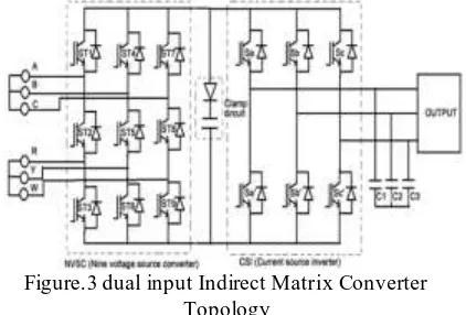
In the proposed dual input matrix converter, the conversion pattern takes place in two sections, first to convert AC to DC by using a nine voltage source converter (NVSC) or matrix converter section and then another conversion takes place by using an inverter to convert DC to AC. For given two input sources is not possible to give an directly AC to the grid side that’s why by using an inverter to converting DC to AC. By using an foil capacitor and cla mp circu it, the DC voltage can be stored and another on thing is the input frequency is lesser than the output frequency so the dual input matrix converter having an boosting capability and Accurate pure sinusoidal output voltage and input current and Figure3.shows an dual input matrix converter [DIMC] instead of nine voltage source converter [NVSC] and Current source inverter [CSI].
The matrix converter has several advantages
over traditional rectifier-inverter type power
frequency converters. It provides sinusoidal input and
output waveforms, with minimal higher order harmonics and no sub harmonics; it has inherent bi-directional energy flow capability; the input power factor can be fully controlled.
Figure.3 dual input Indirect Matrix Converter Topology
The main feature of this device is to convert the magnitude as well as the frequency of the input into a desired magnitude and frequency of the output with an “all-silicon” solution. Mainly, a Matrix Converter consists of nine bi-directional switches, which are required to be commutated and sequence in order to minimize losses and produce the desired output with a high quality input and output waveforms.
Figure 4.Block d iagra m o f simu lation with dual input and dual output
Applications areas of power converters still improve ments in semiconductor technology, which order higher voltage and current ratings as well as better switching characteristics.
• The dual input matrix converter is a
converter, that consists of two input AC sources, nine voltage source converters (NVSC), Current source inverter, and Diode and foil capacitor.
• The circuit operation of Dual input matrix
converter directly consists of operation AC-DC-AC because here using two input AC sources, so bidirectional switch is not possible to get an output from another direction of switch.
• The matrix converter can be classified into
IJEDR1702188
International Journal of Engineering Development and Research (www.ijedr.org)1133
• They are: 1) Indirect Dual matrix converter; 2) Direct Dual matrix converter.
V. S IMUTATION RES ULTS
The Dual Output Indirect Matrix Converter was simulated using MATLAB Simulink. Simulat ion parameters are listed in Table II.
Table II Simulati on Par ameters
Upper load currents, lower load currents and source current are shown in Fig. 5. In Fig. 5, source voltage for only one phase is shown. According to simulat ion results, good output load current tracking is obtained.
Figure 5. Source Vo ltage (top), Upper and Lo wer Load currents (middle), Source current (bottom) Upper load current THD is 2.37% and lowe r load current THD is 2.23%. Min imization of the instantaneous reactive power is achieved and source current THD is 21.73%. In order to evaluate dynamic behavior of the predictive control technique, the system step response is shown in Fig. 6.
Figure 6. Step response of the predictive controller
Model predictive control technique is able control two ac loads even when their frequencies and magnitudes are different. Two ac loads are controlled independently by solving single multi-objective cost function.
The proposed method always provides positive dc-link voltage.
Figure 7. DC-Lin k Vo ltage
Fig.7 shows that dc-link voltage is a lways positive. The State Elimination process in the control scheme always provides positive dc-link voltage, which is important for proper operation. The main idea of the state elimination process is that switching combinations of the rectifier stage that generate a negative dc-link voltage are eliminated and future load current for upper load and lower load are calculated using only proper switching combination of the rectifier stage
Figure 8. Source Current (top) and Instantaneous Reactive Po wer (bottom)
Fig.8 shows source current and instantaneous reactive power both with reactive power control and without reactive power control. Weighting factor C is initia lly set at zero so that reactive power is not controlled.
VI. CONCLUS ION
In this paper proposes a new model predictive control with dual input dual output indirect matrix converter. This control scheme uses a discrete-time model of the converter and predicts load current and reactive power to determine the best suited switching combination by solving a multi-objective optimization proble m. Model predict ive control technique provides fast dynamic response and good steady-state behavior. Model Predictive Control technique is tested for diffe rent control objectives and it performs well under the different conditions.
Simu lation results show that good system
performance was obtained with predictive control scheme in steady state and under transient conditions. The ma in advantage of the predictive control approach is easy imple mentation and fle xibility. This paper presents a finite control set model predictive control strategy for a dual-input dual-output indirect matrix converter. By using the simulat ion results the proposed method is analyzed.
IJEDR1702188
International Journal of Engineering Development and Research (www.ijedr.org)1134
[1] Rodriquez J., Rivera M., Kolar J., Wheeler P., “ARevie w of Control and Modulation Methods for Matrix Converters”, IEEE Transactions on Industrial Electronics, Vo l. 59, No. 1, January 2012
[2] Kola r J., Fried li T., Rodriguez J., Wheeler P., “Review of Three-Phase PWM AC-AC Converter Topologies”, IEEE Transactions on Industrial Electronics, Vo l. 58, No. 11, Nove mber 2011 [3] Dehghan S.M., Yazd ian A., “Hybrid Electrical Vehic le Based on Bid irectional Z-Source Nine Switch Inverter”, IEEE Transactions on Vehicu lar Technology, Vol. 59, No. 6,Ju ly 2010
[4] Liu X., Wang P., Loh P.C., Blaab jerg F., “ A
Co mpact Three-Phase Single-Input/Dual-Output
Matrix Converter”, IEEE Transaction on Industrial Electronics, Vo l. 59, No. 1, January 2012
[5] Nguyen T., Lee H., “Modulation Strategies to Reduce Co mmon -Mode Voltage for Indirect Matrix Converters”, IEEE Transactions on Industrial Electronics, Vo l. 59, No. 1, January 2012
[6] Rodrique z J., Ka zmierkowski M.P., Espinoza J.R., Abu-Rub H., Young H.A., Ro jas C.A., “State of the Art of Fin ite Control Set Model Predict ive Control in Po wer Electronics”, IEEE Transactions on Industrial Informat ics, Vo l. 9, No. 2, 2013
[7] Rodriquez J., Pontt J., Silva C., Correa P., Le zana P., Cortes P., Ammann U., “Pred ictive Current Control of a Voltage Source Inverter”, IEEE Transactions on Industrial Electronics, Vo l. 54, No. 1, February 2007
[8] Va rgas R., A mmann U., Rodrique z J.,
“Predictive Approach to Increase Efficiency and Reduce Switching Losses on Matrix Converter”, IEEE Transactions on Power Electronics, Vol. 24, No. 4, April 2009
[9] Quevedo D., Aguilera R., Pe re z M., Co rtes P., Lizana R., “Model Predictive Control o f an AFE Rectifie r with Figure 5. DC-Link Voltage Figure 6. Source Current (top) and Instantaneous Reactive Power (bottom) Dynamic References”, IEEE Transactions on Power Electronics, Vo l. 27, No. 7, July 2012
[10] Dehghan M., Amiri A., Mohamad ian
M.,Andersen M., “Modular space-vector pulse-width modulation for n ine-switch converters”, IET Po wer Electronics, pp. 1- 11,iet-pel.2012.0203
[11] Dehghan M., Mohammad ian M., Ya zd ian A., Ashrafzadeh F., “Space Vectors Modulation for NineSwitch Converters”, IEEE Transactions on Power Electronics, Vo l. 25, No. 6, June 2010