Smart Grid Security with Cryptographic Chip
Integration
Adesh Kumar
1*
, Priyanshi Vishnoi
2, Shimi S. L.
21Department of Electrical & Electronics Engineering, School of Engineering, University of Petroleum and Energy Studies (UPES), Dehradun, India
2Department of Electrical Engineering, National Institute of Technical Teachers Training and Research (NITTTR) Chandigarh, India
Abstract
Smart grid is the modern digital electricity delivery system based on duplex communication between electrical grid and consumers. The smart grid includes several operations and energy measures comprising renewable energy sources, smart meters, smart devices, and energy efficient resources. The presence of all smart and efficient components on the smart grid involves the Information and Communication Technology (ICT) layer in order to meet the requirements of grid monitoring, control and information interchange for smooth operation of grid. The duplex communication flows conveys cyber security concerns to the smart grid. It is required to countermeasures different cyber security algorithms to the heterogeneous smart grid based on computational resources availability, confidentiality and integrity. The paper proposed the cryptographic based encryption and decryption approach could be employed in smart grid distribution system hardware. A new TACIT algorithm hardware chip is proposed for secured grid communication. The chip design is carried in Xilinx ISE 14.2 software and verified on SPARTAN-3E FPGA hardware. The functional simulation is also done for 64 bit and 128-bit key size on Modelsim 10.0 software. The hardware parameters, memory and timing parameters are extracted directly form Xilinx Software and compared with the existing security protocols. The projected research work will be the advantage for the power industries working on the concerns about the integration of smart grid security concerns with FPGA based systems.
Keywords: Smart grid security, Cryptographic Encryption and Decryption, FPGA synthesis, TACIT algorithm
Received on 23 November 2018, accepted on 28 January 2019, published on 21 March 2019
Copyright © 2019 Adesh Kumaret al., licensed to EAI. This is an open access article distributed under the terms of the
Creative Commons Attribution licence (http://creativecommons.org/licenses/by/3.0/), which permits unlimited use, distribution and reproduction in any medium so long as the original work is properly cited.
doi: 10.4108/eai.13-7-2018.157037
*Corresponding author. [email protected]
1. Introduction
The power and energy are the key aspects for the development of our society. The electrical grid is the mainly consist of the generation station for the production of electricity, high voltage transmission lines for carrying power from one place to another and demanded centers, distribution lines to provide connectivity to individual customers. The power systems are mitigating from the ordinary grid to smart grid to meet the requirements of the current generations and need of society. The research is going in this field since long time. Smart grid is [1, 2] a distributed and computerized network that provides the feasible and two-way communication infrastructure to consumers at least
requirements and issues, the concept of smart grid is bring together which provides two-way communication and delivers electricity based on different demands between suppliers and consumers. It can control the consumption of electricity in distribution and utilization end.
The existing systems are mechanical system having consist of different wires, transformers, cables, interconnected links etc. and provides us uninterrupted power supply. It is the current requirement of the existing grid that the distribution should be smart and controlled electronically and association should be with some intelligent sensors and electronic communication infrastructure. Although all the electronic system need power to energize, so it becomes very essential to ensure that the power system should be more efficient and reliable.
The demand of power is greater than its supply and it is unpredictable, fluctuating with time. Sometimes we can trust on renewable energy resources like wind and solar panels to meet the current need but they are also giving fluctuating supply. The smart grid [3, 4] increases the performance of power system. The main reason is that the grid is consist of electronic intelligent devices, communication, smart metering, sensors, communication technologies [3, 4] and control techniques to make the system smart. The main purpose of the smart grid is to ensure power supply in reliable mode, optimize the existing hardware and provide cost effective solutions to customers. The biggest advantage of the smart grid its cost effectiveness. The grid communication is based on the internet. It uses TCP/ IP, ethernet communication, and other operating systems because internet communications can provide the cyber-attacks [5]. The attackers can also effect the system, disturb the grid load and metering operations of the system. It is required to enhance the grid security and prevent it from attacks.
The electricity has one simple necessity that it should be operated as soon as it is generated. The current grid does so effectively. However, the existing grid working conditions is overloaded. It has been noticed that the reliability of the present grid is at stake, since it have indorsing more blackout and brownouts recently. It is also need to understand that smart grid is better technology for energy transmission and distribution worldwide. The grid is facing critical concerns about its security . The present grid has a central architecture, and thus creating it more susceptible to attackers. The major thrust includes intelligent load management, advanced metering and improving system reliability. Smart power control grid generates a connection between electricity, computer control and communication. Many countries are taking active participation in the expansion of smart grid. The current research work can be emphasized on the design and implementation of secured infrastructure and communication architecture for smart grid. Therefore, the main objective of grid is to control the amount of power supply with greater efficiency and minimize the carbon
emissions. The typical smart grid system should support the following properties
Digitalization Intelligence Resilience Customization Flexibility
Figure 1 Smart grid properties [8]
Digitalization means that system is working in digital domain, enhance the system speed and make it consistent. The meaning of flexibility is that the smart grid is compatible, adaptable and expandable. The mean of intelligent is to exploit intelligent technology with intelligent devices. Resilience means that the grid system must be free from any hackers and attacks. Customization means that the system should be able to meet the prerequisites and can be client tailored. In current scenario, the existing power grid is very intelligent and system. The power grid consist of thousands kilometre high voltage lines. These lines are controlled by an intelligent control, provide communication infrastructure with distributed system that distributes it over customized network. The smart grid help the society to increase the availability and efficiency of the same power system using better control strategies. The scalable means the same structure would be applicable for different networks with programming facility and network size can support multiple lines.
The cyber security models require fulfilling three main objectives like any other security networks. It should focus on security features such as availability, integrating and confidentially that is the accessibility of electricity with incorporation of customer’s information and privacy.
requirement. Availability is very much important because it delivers the metric for identification of the likelihood that grid system is functional.
Confidentiality - The user information is confidential. The grid network should be responsible for the data protection and customer’s information. If the information is not secured, attacker can use the sampled information to crack the confidential data of user.
Integrity-The messages received from the consumer end should be authenticated on regular basis. The network should guarantee that the information is not corrupted. It is also essential that the source of messages transmission is authentic. A scalable, persistent and ubiquitous and infrastructure is expected for management and complete operation of smart grid technology.
The smart grid a developing project worldwide. The automation and its implementation will consequence frequent advantages for the society. However, it has to face a many challenges and issues when security is considered. Cyber-attacks and threats is an essential part of the grids security as major concern. As the grid expands and develops in the forthcoming years, the communicating nodes will dispose to cyber-attacks. The cryptography and key management methods is applied to protect the system contrary to cyber-attacks. The system should be free from any concern and threats of security in order to provide more reliable and secured grid communication. The research work can be focused on Field Programmable Gate array (FPGA) implementation of security protocols with the integration of smart grid communication hardware as the design of reliable communication platform is main feature for grid availability, security and integrity. The security contests to transmission control protocol /Internet Protocol (TCP/IP) is considered as major concerns for grid network. Therefore, software and hardware implementation of protocols and integration with FPGA will make system fast and reliable for TCP/IP protocol. The FPGA implementation is more preferable technology as FPGAs include I/O controller, memory and multipliers blocks. It is not anymore a single chip of an embedded application rather than network on chip (NoC) or reconfigurable system on chip (SoC). The security issues is required to address in all embedded application that includes sensing, wireless, and actuation functions. The smart grid is also integrated with such embedded applications and FPGA based system implementation with grid infrastructure will be cost effective solution rather than for an ASIC implementation.
2. Related Work
The extensive research work has been carried in the area of smart grid requirements, communication and security.
Ancillotti E. et al [1] presented the conceptual model for
smart grids of communication systems. The model was based on the identification of operational components, associated technologies, network topology and communication services essential to support smart grid communications. They proposed that wireless sensor network based communication for smart grid is a challenging task for robust and consistent low-power wireless communication. Aggarwal A et al [2] discussed the requirements for a robust communications infrastructure for the future smart grid and bandwidth constraint for a hypothetical grid infrastructure. The smart grid architectures are based on technology related to sensing, communication, and control. Optical fiber is the transmission medium for communication for smart grid.
Bari A. et al [3] detailed, numerous features of the smart grid based on security, energy management and communication infrastructure. The smart grid can provides more benefits when it is more reliable and secured as a network solution. Bharothu J. N. et al [4]
discussed that smart grid offers advance grid security and reliability and analysis in information protection and physical protection services. Chhaya L. et al [5]
discussed that the smart grid technology is based on automatic metering infrastructure, full duplex communication, renewable energy integration, distribution, complete monitoring, automation and control of whole power grid. The communication system based on wireless sensor networks (WSN) is the great asset for monitoring, control and gathering the data from surroundings. The major concern of wireless sensor based communication network is its security against cyber-attacks. Crope F et al [6] suggested the new techniques for encryption and decryption based on secured policy based routing. They suggested new TACIT algorithm for symmetric key cryptographic approach. The biggest advantage of the suggested algorithm is that the key size and block size can vary upto ‘n’ bit. Fadel E. et al [7]
synthesized on Spartan-6, XC6SLX45 FPGA based on repetitive looping method with 128 bits key size and block size.Kumar A. et al [11] implemented the TACIT logic for network on chip (NoC) applications to provide secured communication. The design was based on VHDL programming, simulated for 512 and 1024-bit plain text and synthesized on Virtex-5 FPGA. Lee S. et al [12]
discussed smart grid logical architecture centric for Home Area Network (HAN)-mainly handles customer’s personal information. They suggested security architecture to defend the HAN customer’ personal information and efficiently deliver services for users.
Priya S. S et al [13] proposed an efficient cryptographic structural architecture for AES encryption algorithm to realize high throughput and less device utilization. The architecture was used for 128 bit block size and key size following ‘S’ box technique. The 128-bit encryption design was implemented on Spartan 3, Virtex-4 and Virtex-5 FPGA Devices. Ranganathan R. et al [14]
integrated smart grid and cognitive radio IEEE 802.22 standard for communication infrastructure. They also addressed problem of smart grid security using FPGA-based fuzzy logic intrusion detection. Rao, M. R. et al [15] designed memory less AES encryption and decryption algorithm architecture. They suggested the concept of round key for encryption and decryption to provide minimum hardware and power consumptions. The design was filled in 1 clock cycle and 128 bit AES was completed in 10 clock cycles. S. Shapsough et al [16] discussed that cyber security in the smart grid network is serious concern. They suggested low power Wireless Personal Area Networks (6LoWPAN) to address the various entities in IP-based communication system and security protocols of smart grid.Strasser T. et al [17]
addressed on the current need of automation and artificial intelligence required for future infrastructure if electrical grid. It is also discussed the most significant standards required to satisfy the interoperability in distributed environment such as high penetration of grid under Distributed Energy Resources (DER). Wang W. et al [18]provided an inclusive survey on the communication architectures in the power systems, technologies, functions, communication network compositions, requirements, and research challenges. Grid security is the main concern as the integration of electric grid with communication network require regular monitoring. Yan Ye et al [19] motivated that smart grid infrastructure and communication is a very encouraging filed and built on latest technologies of communications, sensing, and control. Grid reliability, security and efficient behavior of interrelated devices are critical aspects to enable smart grid communication.Zodpe, Harshal et al [20] proposed new AES security algorithm with hybrid non-pipelined structure. PN sequence generator is used to assign the values of S-box required for encryption/encryption with 128-bit key size.
Most of the researches have addressed the security issues in smart grid distribution system. The energy is the
premium resource of society. Ensuring grid security against theft, malicious attacks and abuse in a smart grid is of crucial concern. It is possible to solve the smart grid security with then help of cryptographic encryption and decryption with the secured key algorithm. In security also the algorithm are limited to their key or password size. Research can be focused on TACIT encryption and decryption, which is not implemented in hardware chip yet. The results of smart grid can be verified with large scale FPGA and validation can be carried in secured communication infrastructure. With the design of the network security protocol, there is a huge scope to increase the reliability on the smart grid.
3. Cryptography as Proposed Solution
Cryptographic based approach can be a good solution for the security in communication system to achieve protected information and secured communication. In smart grid, there are electronics devices embedded with lost cost hardware. They can follow the cryptographic approach of encryption and decryption [9, 11] with public key cryptography. The design of encryption and decryption scheme is essential to provide data integrity and data confidentiality in the smart grid. In Cryptography, encryption the original message or data referred as plain text, which is encoded with key value, called cipher text and transmitted over a channel. Decryption is the reverse process, in which the plain text is decoded from the cipher text. With the help of secret key and cipher text, it produces the original plain text.
3.1 TACIT Algorithm
The TACIT encryption logic [6, 9] for data communication between two nodes of smart grid is presented with the help of following algorithm.
Step 1: Initially the contents of text file is read as the plain text and position of the character is shuffled using the concept of primary permutation approach with the help of key value.
Step 2: Each character has its ASCII value. Read the character from the text file corresponding to the plain text and follow the ASCII value of that character.
Step 3: Accomplish XOR operation specifically with n-bit key value.
Step 4: Apply the TACIT logic concept has been familiarized (i.e. nk xor kk along with some specific operations; in which ‘n’ is the value obtained from step 3).
Step 6: Apply the bit reverse operation on the converted binary string.
Step 7: Found the decimal value against each binary string.
Step 8: The Unicode character is formed corresponds to the decimal value, which is nothing other than the cipher text.
Step 9: Follow all encryption steps continued from step 1 to step 7 for the subsequent characters of the text file till End of File (EoF) is not reached.
The decryption of same data is done at receiving end. The text, encoded at transmitting end using TACIT encryption technique is called cipher text. The decryption algorithm [9] decodes the cipher text with the same key at the receiving end that follows the steps listed below
Step 1: Read the first character from the contents of the cipher text and refer the corresponding decimal value of character.
Step 2: Determine the corresponding binary and apply the bit reverse operation of it.
Step 3: Apply the concept of inverse of the tacit logic.
Step 4: Accomplish the XOR operation with n-bit key value.
Step 5: Determine the characters corresponding to the value after XOR operation.
Step 6: Now, reorganizing the contents using key value.
Step 7: Repeat all the decryption steps from (1 to 6) until end of file is achieved.
4. Results & Discussions
4.1 Simulation Results of Encryption Logic
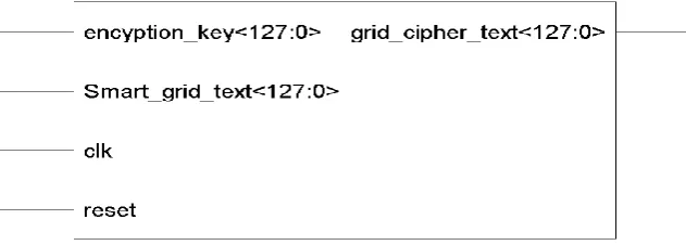
RTL view is a top view representation depicting designed chip pins details and input/ output logic. The possible
inputs and ouputs used in the development of the chip are represented with their RTL view. Figure 1 represents the chip view as RTL of smart grid TACIT encryption logic taken from Xilinx ISE 14.2 Software. The detail of the chip view and pins is given in table 1. The Modelsim functional simulation is shown in Figure 2 for the 64 bit encrypted data followed by smart_grid_text <63:0> and encryption_key<63:0>. Figure 3 presents the Modelsim simulation of 128-bit smart grid text and 128 by key size by smart_grid_text <127:0> and encryption key<127:0>. The simulation steps are given as
Step input 1: reset = ‘1’, apply clock signal. It provides positive or rising clock pulse to check the results of applied clock signal with 50% duty cycle.
Step input 2: reset = ‘0’, apply clock signal. Choose text value form all signals inputs and then force. Force Smart_grid_text <63:0> = “01001101 01100101 01110100 01100101 01110010 00100000 01001111 01001110” in binary or 1'h4D65746572204F4E (Meter ON) in ASCII. For Encryption_key<63:0> = “01001110 01101001 01010100 01010100 01010100 01010010 01000000 01000000”in binary or 1'h4E49545454524040 (NITTTR@@) in ASCII.
Step input 3: reset = ‘0’, apply clock signal. Choose text value form all signals inputs and then force. Force smart_grid_text <127:0> = “01000111 01110010 01101001 01100100 00100000 01001111 01001110 00100000 01001101 01100101 01110100 01100101 01110010 00100000 01001111 01001110” in binary or 1'h 47726964204F4E204D65746572204F4E (Grid ON Meter ON) in ASCII. Force Encryption_key<127:0> = “01001110 01101001 01010100 01010100 01010100 01010010 01000000 01000000 00110001 00110010 00110011 00110100 01000011 01101000 01100100
01000000”in binary or
1'h4E495454545240403132333443686440
(NITTTR@@1234Chd@) in ASCII. The simulation is carried with grid parameters: Primary Voltage = 230 V, Secondary Voltage = 117 V, grid temperature = 400C, Frequency = 50 Hz and Power = 2W.
00100000 00110010 00010100 01000011 10000100” in binary or 1'h0000002032144384 (hexadecimal).
Table 1 Pins details for smart grid TACIT encryption logic
Pins Direction Description
Smart_grid_text <127:0>
(128 bit)
Input It presents the grid input data as textual text of the encryption end. The size of the text can vary of ‘N’ bit, simulation results shows the results for 64 bit and 128 bit.
Encryption_key<127:0>
(128 bit)
Input It presents the input key as password of the encryption end. The size of the text can vary of ‘N’ bit, simulation results shows the results for 64 bit and 128 bit.
Clk (1 bit) Input It is the input of 1 bit used for synchronization and provides clock pulse to work digital logic at 50 % duty cycle
Reset (1 bit) Input Reset pin is used to reset the logic circuitry and synchronized with clock pulse.
Grid_cipher_text<127:0> (128 bit)
Output It is text, which is achieved at transmitting end. In our case, the size is of 64 bit and 128 bit. It can be any garbage value.
Figure 2 Modelsim output waveform of encryption logic in ASCII (64-bit key size)
4.2 Simulation Results of Decryption Logic
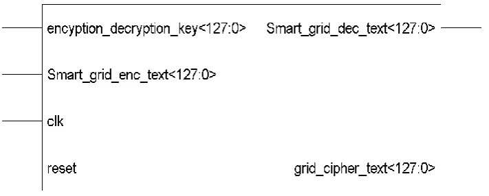
The decryption is the reverse process of the encryption and considered at receiver or the consumer device end in smart grid. Figure 4 represent the chip view as RTL of TACIT decryption logic extracted from Xilinx ISE 14.2 Software. The detail of RTL view of smart grid TACIT decryption logic is give in table
2.
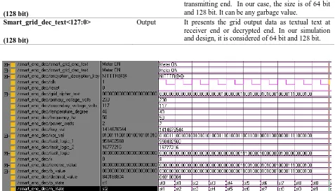
The Modelsim functional simulation is shown in Figure5
for the 64bit
decrypted data followed by
smart_grid_enc_text <63:0>, encryption_decryption_key<63:0> and smart_grid_dec_text<63:0>. Figure 6 presents the Modelsim simulation of 128-bit smart grid text and 128 by key size. The simulation steps for smart_grid_enc_text <127:0>, encryption_decryption_key<127:0> and smart_grid_dec_text<127:0>.
The simulation steps are given asStep input 1: reset = ‘1’, apply clock signal. It provides positive or rising clock pulse to check the results of applied clock signal with 50% duty cycle.
Step input 2: reset = ‘0’, apply clock signal. Choose text value form all signals inputs and then force. Force Smart_grid_enc_text <63:0> = “01001101 01100101 01110100 01100101 01110010 00100000 01001111 01001110” in binary or 1'h4D65746572204F4E (Meter ON) in ASCII. Force Encryption_decryption_key<63:0>
= “01001110 01101001 01010100 01010100 01010100 01010010 01000000 01000000”in binary or 1'h4E49545454524040 (NITTTR@@) in ASCII. Force Grid_cipher_text <63:0>. = “00000000 0000000 0000000
Step input 3: reset = ‘0’, apply clock signal. Choose text value form all signals inputs and then force. Force smart_grid_enc_text <127:0> = “01000111 01110010 01101001 01100100 00100000 01001111 01001110 00100000 01001101 01100101 01110100 01100101 01110010 00100000 01001111 01001110” in binary or 1'h 47726964204F4E204D65746572204F4E (Grid ON Meter ON) in ASCII. Force Encryption_decryption_key <127:0> = “01001110 01101001 01010100 01010100 01010100 01010010 01000000 01000000 00110001 00110010 00110011 00110100 01000011 01101000 01100100 01000000”in binary or 1'h4E495454545240403132333443686440
(NITTTR@@1234Chd@) in ASCII. Force Grid_cipher_text <127:0> = “00000000 00000000 00000000 00000000 00000000 00000000 00000000 00000000 00000000 00000000 00000000 00000000 01011000 01000010 00100000 00000000” in binary or
1'h00000000000000000000000058421000(hexadecimal).
The simulation is carried with grid parameters: Primary Voltage = 230 V, Secondary Voltage = 117 V, grid temperature = 400C, Frequency = 50 Hz and Power = 2W.
Figure 4 RTL view of grid encryption logic
Table 2 Pin Details for smart grid TACIT decryption logic
Pins Direction Description
Smart_grid_enc_text<127:0>
(128 bit)
Input It presents the grid input data as textual text of the encryption end or the transmission end. The size of the text can vary of ‘N’ bit. In our simulation results, it is considered of 64 bit and 128 bit.
Encryption_decryption_key<127:0> (128 bit)
clk (1 bit) Input It is the 1 bit input used to provide clock signal to work digital logic at 50 % duty cycle
Reset (1 bit) Input Reset is 1-bit input used to reset the logic circuitry
and synchronized with clock pulse.
Grid_cipher_text<127:0>
(128 bit)
Inout It is text, which is achieved after encryption at the transmitting end. In our case, the size is of 64 bit and 128 bit. It can be any garbage value.
Smart_grid_dec_text<127:0>
(128 bit)
Output It presents the grid output data as textual text at receiver end or decrypted end. In our simulation and design, it is considered of 64 bit and 128 bit.
Figure 5 Modelsim output waveform of decryption logic in ASCII (64-bit key size)
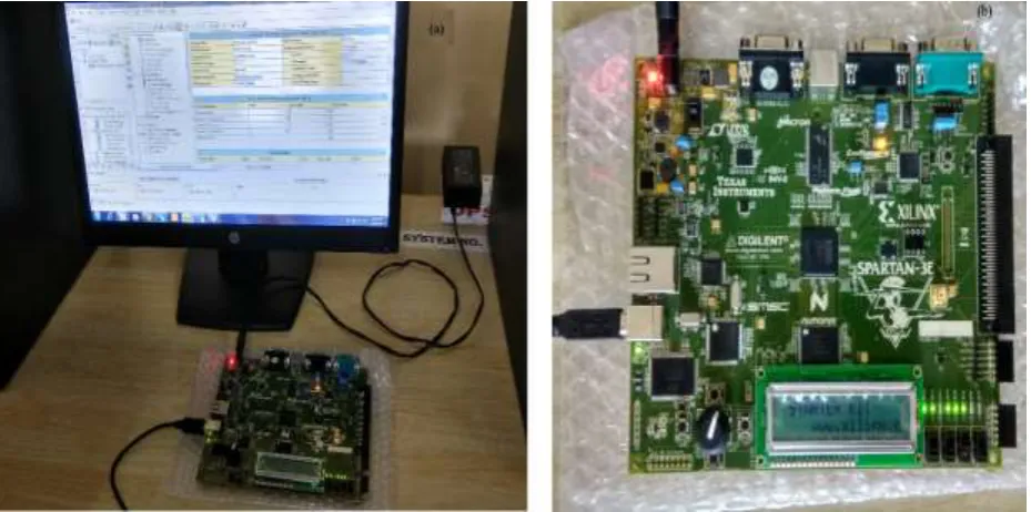
5. SPARTAN - 3E FPGA Synthesis
The data transfer between the transmitting and receiving ends with the same key is verified for smart grid network. It can be understood with the help of different test cases listed below. The synthesis process is limited to 8-bit data transfer due to the availability of 8 I/O pins in FPGA board.
Test Case 1: Apply Clk = Clk, Reset = 1/0, In_SW = “0000”, input data is given on inlet using switches, Output data of is flashed on LEDs, = “01001101”, ASCII code is ‘M’ = 1’h4D (hexadecimal).
Test Case 2: Apply Clk = Clk, Reset = 1/0, In_SW = “0001”, input data is given on inlet using switches, Output data of is flashed on LEDs, = “01100101”, ASCII code is ‘e’= 1’h65 (hexadecimal).
Test Case 3: Apply Clk = Clk, Reset = 1/0, In_SW = “0010”, input data is given on inlet using switches, Output data of is flashed on LEDs, = “01110100”, ASCII code is ‘t’ = 1’h74(hexadecimal).
Test Case 4: Apply Clk = Clk, Reset = 1/0, In_SW = “0011”, input data is given on inlet using switches, Output data of is flashed on LEDs, = “01100101”, ASCII code is ‘e’ = 1’h65 (hexadecimal).
Test Case 5: Apply Clk = Clk, Reset = 1/0, In_SW = “0100”, input data is given on inlet using switches, Output data of is flashed on LEDs, = “01110010”, ASCII code is‘r’ = 1’h72 (hexadecimal).
Test Case 6: Apply Clk = Clk, Reset = 1/0, In_SW = “0101”, input data is given on inlet using switches, Output data of is flashed on LEDs, = “00100000”, ASCII code of space = 1’h20 (hexadecimal).
Test Case 7: Apply Clk = Clk, Reset = 1/0, In_SW = “0110”, input data is given on inlet using switches, Output data of is flashed on LEDs, = “01001111”, ASCII code of ‘O’ = 1’h4F (hexadecimal).
Test Case 8: Apply Clk = Clk, Reset = 1/0, In_SW = “0111”, input data is given on inlet using switches, Output data of is flashed on LEDs, = “01001110”, ASCII code of ‘N’ = 1’h4E (hexadecimal).
The test case shows the 8-bit data decoding at one time verification of FPGA synthesis. The data encrypted is
1’h4D65746572204F4E. It is 8-bit ASCII code and which
decode by FPGA one character at a time. The decoded data is 1’h4D65746572204F4E (Hexadecimal) = Meter ON. The corresponding binary data is flashed on LEDs as show in Figure 7.
Figure 7 Experiment verification on SPARTAN-3E FPGA
5.1 Device Utilization and Timing Summary
Device utilization description provides the utilization of hardware devices for the chip design. Device hardware contains number of slices, number of input LUTs, number
maximum output required time after clock signal. Total memory utilization required to complete the design is also given. The target device is 3s500efg320-5 of SPARTAN-3E FPGA. Table 3 and table 4 presents the hardware device utilization summary for smart grid TACIT encryption and decryption logic respectively. Table 5 presents the timing parameters summary for smart grid TACIT encryption and decryption logic.
5.2 Comparative Analysis
The comparative analysis of the proposed TACIT algorithm is done with the popular AES algorithm work Kouser Zabina (2016), Rao M.Rajeswara (2017) and Zodpe Harshali (2018) for 128-bit encryption-decryption logic. Table 6 compares the parameters such as No. of
slices, flip-flops, slice LUTs, throughput and maximum frequency support. The Comparative hardware utilization graph of TACIT algorithm with existing AES algorithm is depicted in Figure 8.
Table 3 Device utilization summary for smart grid TACIT encryption logic
Hardware Parameter Utilization
64 bit 128 bit
Number of Slices 393 out of 4656 8.4% 393 out of 4656 8.4%
Number of Slice Flip Flops 241 out of 9312 2.5% 241 out of 9312 2.5%
Number of 4 input LUTs 706 out of 9312 7.5% 706 out of 9312 7.5%
No. of bounded I/OBs 96 out of 232 41.37% 160 out of 232 68.96%
Number of GCLKs (Gated Clk) 1 out of 24 4.16% 1 out of 24 4.16%
Total memory usage (kB) 123120 kB 125744 kB
Table 4 Device utilization summary for smart grid TACIT decryption logic
Hardware Parameter Utilization
64 bit 128 bit
Number of Slices 80 out of 4656 1.71% 80 out of 4656 1.71%
Number of Slice Flip Flops 139 out of 9312 1.49% 139 out of 9312 1.49%
Number of 4 input LUTs 133 out of 9312 1.42% 133 out of 9312 1.42%
No. of bounded I/OBs 129 out of 232 55..60% 193 out of 232 83.16%
Number of GCLKs (Gated Clk) 1 out of 24 4.16% 1 out of 24 4.16%
Total memory usage (kB) 109808 kB 111856 kB
Table 5 Timing summary for smart grid TACIT encryption and decryption logic
Timing Parameter Encryption (64/128 bit) Decryption(64/128 bit)
Frequency (Max) 258.799 MHz 309.215 MHz
Period (Minimum) 3.864 ns 3.234 ns
Time before clk (minimum) 6.261 ns 5.316 ns
Time after clock (maximum) 6.897ns 6.897 ns
Speed Grade -5 -5
Table 6 Comparison with Existing AES Algorithm
Parameter Kouser Zabina
(2016)
Rao M.Rajeswara (2017)
Zodpe Harshali (2018)
Proposed Work
No. of Slices 957 953 697 393
Flipflops 499 0 241
Slice LUTs 1459 3246 706
Frequency 239.958 MHz - 372.98 MHz 309.215 MHz
Figure 8 Comparative hardware utilization graph of TACIT algorithm with existing AES algorithm
6. Conclusion
The smart grids is the modern digital technology for the Nation to increase the power production and reduces the power loss and downtime. The integration on the electrical grid with the information and latest communication technologies has been identified the supreme technology for the grid itself. Several ideas in power generation communicate with each other to take the smart and intelligent decisions based on shared communication. The security of the grid in distribution end is the biggest concern. The research work emphasized on smart grid and its security issues. The issues can be resolved with the integration of chip of cryptographic encryption and decryption. There are many algorithm such as AES, DES, XMODES, RC5 etc but limited to key size and block size in hardware chip implementation. The hardware chip implementation of the TACIT logic for encryption and decryption is done in the Xilinx 14.2 and functional simulated in Modelsim the 10.0. The encryption and decryption chip integration of TACIT logic has proven best result in comparison to the other techniques available for encryption and decryption. The results of smart grid TACIT security are simulated and synthesized based on SPARTAN 3E FPGA hardware. The Hardware and timing parameters summary report is also analyzed based on the resources utilization targeting the same FPGA.It is clear that TACIT is consuming less hardware resources in comparison to existing AES algorithm and latest work by Kouser Zabina (2016), Rao M .Rajeswara (2017) and Zodpe Harshali (2018) for 128-bit encryption-decryption logic. The timing results are
also optimized in terms of minimum time before clock, maximum time after clock and combinational path delay.. The maximum frequency support is 309.215 MHz, which is also optimal in comparison to Kouser Zabina (2016) which suggest that our design is faster. The proposed research work will be the boon for the power industries working towards the integration of smart grid security concerns with FPGA based system.
References
[1] Ancillotti, E., Bruno, R. and Conti, M. (2013) The role of communication systems in smart grids: Architectures, technical solutions and research challenges. Computer Communications, Elsevier Vol. 36(17-18), pp.1665-1697. [2] Aggarwal, A., Kunta, S. and Verma, P.K. (2010), A proposed communications infrastructure for the smart grid. In Innovative Smart Grid Technologies (ISGT),
IEEE (pp. 1-5).
[3] Bari, A., Jiang, J., Saad, W. and Jaekel, A. (2014). Challenges in the smart grid applications: an overview. International Journal of Distributed Sensor Networks, Sage Publisher, Vol. 10(2), pp (974682). [4] Bharothu, J.N., Sridhar, M. and Rao, R.S., (2014) A literature survey report on Smart Grid technologies. In Smart Electric Grid (ISEG), 2014 IEEE International Conference (pp. 1-8).
[6] Crope, F., Sharma, A., Singh, A. and Pahwa, N. (2011) an efficient cryptographic approach for secure policy based routing :(TACIT Encryption Technique). In Electronics Computer Technology (ICECT), 2011 3rd International Conference on (Vol. 5, pp. 359-363). IEEE. [7] Fadel, E., Gungor, V.C., Nassef, L., Akkari, N., Malik, M.A., Almasri, S. and Akyildiz (2015) a survey on wireless sensor networks for smart grid. Computer Communications, Elsevier Vol.71, pp (22-33).
[8] Iyer, S. (2011) Cyber security for smart grid, cryptography, and privacy. International Journal of Digital Multimedia Broadcasting, Hindawi, pp (1-15). [9] Kaur, M., Kaur, M., Singh, G. (2012) Comparison of TACIT Encryption Algorithm with Various Encryption Algorithms. International Journal of Electronics and
Computer Science Engineering, page (1-10).
[10] Kouser Z, Singhal M, Joshi AM. FPGA implementation of advanced Encryption Standard algorithm. In Recent Advances and Innovations in
Engineering (ICRAIE), 2016 International Conference on
2016 Dec 23 (pp. 1-5). IEEE.
[11] Kumar, A. Kuchhal, P. and Singhal, S (2015) Secured Network on Chip (NoC) Architecture and Routing with Modified TACIT Cryptographic Technique. Procedia Computer Science, Elsevier, Vol.
48, pp (158-165).
[12] Lee, S. ., Kim, J. and Shon, T (2016) User privacy-enhanced security architecture for home area network of Smart grid. Multimedia Tools and Applications, Springer Vol. 75(20), pp (12749-12764).
[13] Priya, S.S. Karthigaikumar, P., Mangai, N.S. and Das, P.K.G. (2017) An efficient hardware architecture for high throughput AES encryptor using MUX based sub pipelined S-box. Wireless Personal Communications, Springer Vol. 94(4), pp (2259-2273). [14] Ranganathan, R, Qiu, R., Hu, Z., Hou, S., Pazos-Revilla, M., Zheng, G., Chen, Z. and Guo, N., (2011) Cognitive radio for smart grid: Theory, algorithms, and security. International Journal of Digital Multimedia
Broadcasting Hindawi, pp (1-15).
[15] Rao, M.R. and Sharma, R.K (2017) FPGA implementation of combined AES-128. In 2017 8th International Conference on Computing, Communication
and Networking Technologies (ICCCNT) (pp. 1-6). IEEE.
[16] Shapsough, S., Qatan, F., Aburukba, R., Aloul, F. and Al Ali, A.R. (2015) Smart grid cyber security: Challenges and solutions. In Smart Grid and Clean Energy Technologies (ICSGCE), 2015 International Conference (pp. 170-175). IEEE.
[17] Strasser, T., Andrén, F., Merdan, M. and Prostejovsky, A. (2013) Review of trends and challenges in smart grids: An automation point of view. In International Conference on Industrial Applications of Holonic and Multi-Agent Systems (pp. 1-12). Springer, Berlin, Heidelberg.
[18] Wang, W., and Lu, Z. (2013) Cyber security in the smart grid: Survey and challenges. Computer Networks, Elsevier Vol. 57(5), pp (1344-1371).
[19] Yan, Y., Qian, Y., Sharif, H. and Tipper, D. (2013) A survey on smart grid communication infrastructures: Motivations, requirements and challenges. IEEE Communications Surveys & Tutorials, Vol. 15(1), pp (5-20).
![Figure 1 Smart grid properties [8]](https://thumb-us.123doks.com/thumbv2/123dok_us/8416736.1692582/2.595.318.551.137.396/figure-smart-grid-properties.webp)