Algorithms of Energy Efficient Control of Electric
Technological Complex for Autonomous Heat Supply
J.V. Breido
1,*, A.A. Kalinin
1and D.V. Lissitsyn
11 Karaganda State Technical University, No.56, Mira B., Karaganda, 100027, Kazakhstan
Abstract
The algorithms for energy efficient control of an electric technological complex with a frequency-controlled electric drive for autonomous heat and hot water supply based on hydrodynamic heaters have been developed. The complex is designed to carry out experimental studies of the problem of reducing energy consumption by hydrodynamic heaters. The functional and process flow sheet of the complex is given. The results of experimental studies confirming the effectiveness of the developed algorithms are presented. Power consumption reducing by 8% was achieved owing to the cyclic operation, and up to 45% due to capacity control of the pump unit.
Keywords: energy efficiency, energy saving, increasing the energy conversion efficiency, autonomous heating systems, hydrodynamic heater, decentralized heating.
Received on 06 March 2018, accepted on 03 May 2018, published on 10 July 2018
Copyright © 2018J.V. Breidoet al., licensed to EAI. This is an open access article distributed under the terms of the Creative Commons Attribution licence (http://creativecommons.org/licenses/by/3.0/), which permits unlimited use, distribution and reproduction in any medium so long as the original work is properly cited.
doi: 10.4108/eai.10-7-2018.155040
*Email: [email protected]
1. Introduction
In the countries of Eastern Europe, the CIS countries, autonomous heat supply systems are actively developing. There are options of the systems realized due to the heat generated from a boiler house, from local electric heaters with heat pumps, photovoltaic and solar-thermal system (PVT), vortex heat generators, etc. As a rule, these are objects of private residential development or remote and isolated enterprises and organizations (flat, house, block) [1-4].
Vortex heat generators or heaters based on the hydrodynamic method of heating liquids are devoid of many disadvantages inherent in heaters using tubular electric heating elements. In particular, with their help it is possible to heat practically any liquid, while the latter are very particular about the quality of the heated water [5]. Their high efficiency, absence of water treatment, expensive heat exchange equipment, electrochemical corrosion, etc. makes them an economically attractive source of autonomous heat and hot water supply [6]. At the same time, one of the main
drawbacks of this type of heaters is significant consumption of electricity.
2. Electric technological complex for
autonomous heat supply (ECAH)
At Karaganda State Technical University a series of hydrodynamic heaters (HDH) of various capacities have been developed, from 5 to 55 kW, which corresponds to the needs of autonomous decentralized heat and hot water supply facilities. In the process of their operation the need to reduce power consumption of the HDH has been identified. To solve this problem, an electric technological complex for autonomous heat supply (ECAH) has been developed [7].
The complex includes the following components: a circulation pump with an electric motor equipped with a frequency converter; a hydrodynamic heater (HDH) with a pipe-type reactor; a heat accumulator tank; pipe and shut-off valves; instrumentation from which output the data are transmitted to a personal computer with SCADA-system installed.
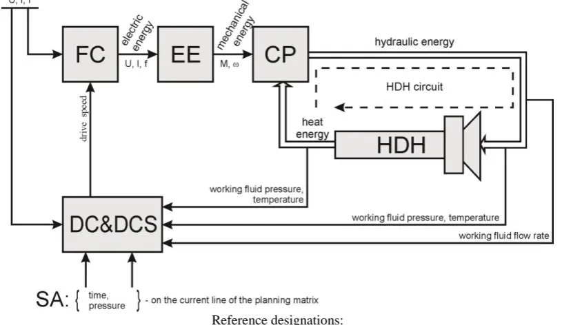
The functional diagram of the complex is shown in Figure 1.
Reference designations:
FC – frequency converter; EE – electric engine; CP – centrifugal pump; HDH – hydrodynamic heater with a pipe type reactor; DC&DCS – dispatcher control and data collection system; SA – setpoint adjuster
Figure 1. Functional diagram for the experimental studying of the electric technological complex
of autonomous heat supply
In the ECAH the consumed electrical energy is subsequently converted into mechanical energy (the pressure developed by the pump), then into hydraulic energy (the energy of the moving working fluid) and, as a result, into thermal energy (developing the effect of cavitation on special structural elements).
3. Research tasks
Increasing the energy efficiency of hydrodynamic heaters is possible both at the stage of their design and when optimizing the ECAH operation modes. Five patents have been received for design technical solutions [8]. The essence of these solutions is increasing the efficiency of hydraulic energy conversion into thermal energy.
There exist the following possible options for reducing power consumption by the ECAH complexes during operation:
changing the operating modes within a day;
controlling the operation of the electric motor of the circulation pump (on-off) when reaching the boundary temperatures of the coolant;
controlling the starting mode of the electric motor of the circulation pump;
changing the speed of the electric drive of the pumping unit in the established thermal processes.
In connection with the complexity of the mathematical description of the stages of electrical energy conversion into thermal energy, the algorithms for the energy-efficient controlling of the ECAH have been developed and corrected in the course of experimental studies.
For experimental research the following tasks have been set:
(i) by changing the operating modes of the electrical equipment of the complex to reduce energy consumption of the ECAH for obtaining and maintaining thermal energy;
(ii) to assess the effect of changing the speed of the electric drive of the pump unit by frequency regulation for the energy efficiency of the complex operation.
4. Algorithms of controlling the ECAH
working modes
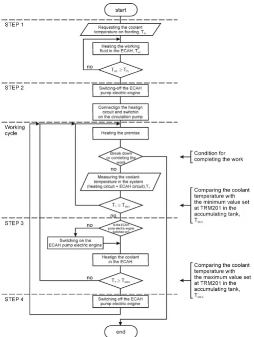
Let's consider two options of the algorithm for controlling the operating mode of the electric technological complex ECAH. Algorithm No. 1 (Figure 2):
Figure 2. Algorithm No.1
(i) Heating the working fluid in the HDH circuit (Figure 1) to the temperature of the heat carrier at the supply pipeline of the object heat supply system (step number 1 of the algorithm in Figure 2).
(ii) Connecting the loading circuit (heat supply system of the object) to the ECAH (step 2 of the algorithm). The load circuit has its own pump that ensures constant circulation of the coolant. A temperature sensor is installed in the ECAH heat accumulator tank. It is connected with the temperature meter TRM201 of the OVEN company that is a part of the instrumentation complex. At TPM201 the hysteresis of the temperature range in the storage tank is set. For example, the minimum value of the coolant temperature is + 35 °C, the maximum one is + 45 °C.
(iii) When the coolant temperature drops (due to heat loss) to the minimum value, the HDH pump is automatically switched on and runs through the HDH and heats the coolant to the maximum set value (step 3 of the
algorithm). The loading circuit is not switched off, i.e. the total volume of the heat carrier is equal to the sum of the volumes of liquids in the HDH set and in the heat supply system of the object.
(iv) When the maximum value of the coolant temperature is reached, the HDH circulating pump is switched off (step 4 of the algorithm). The loading circuit pump continues operating. The gradual cooling of the coolant (due to heat loss) takes place to the minimum value and then the algorithm is repeated according to the working cycle and the third step.
Algorithm No.2 (Figure 3):
(i) Connecting the loading circuit to the ECAH (step 1 of the algorithm in Figure 3).
Figure 3. Algorithm No. 2
(ii) Switching on the HDH circulating pump that performs a run through the pump and heats the heating medium. At this the loading circuit pump also works. The total volume of the heating medium to be heated is equal to the sum of the volumes of liquids in the HDH set and in the parking supply system (step 2 of the algorithm). (iii) When the maximum value of the coolant temperature is
4.1. Experimental verification of the
algorithms
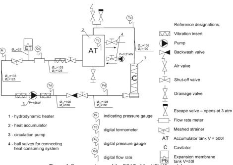
For experimental verification of the algorithms, the ECAH set of the HDH45 model (Figure 4) has been selected and investigated in the parking of an office building in Astana (Kazakhstan). The system of heat supply of parking has been switched off from the central heat supply and connected to the ECAH unit of the HDH45 model. The parameters of the system of heat supply of parking are as follows:
the temperature of the heat carrier at the supply pipeline of the heat supply system is 76 °C;
the heat carrier temperature at the return pipeline of the heat supply system is 40 °C;
the pressure at the supply pipeline of the heat supply system is 0.74 MPa;
the pressure at the return pipeline of the heat supply system 0,4 MPa;
the total parking area is 1064 m2, its height is 4 m;
the coolant volume in the system is 0.54 m3.
The volume of the working fluid (tap water) in the HDH45 circuit is 0.65 m3.
Figure 4. Process scheme of the ECAT of the HDH45 model
On November 9-10, 2014 there were carried out two series of experiments for the abovementioned algorithms taking into account the additional data of Table 1.
Table 1. Additional initial data for the experiments
Parameter 1 series of experiments
2 series of experiments
The temperature of the radiator surface, С
34 32
The air temperature in the parking, С
17 15,5
The initial temperature in the HDH storage tank, С
15 24
The results of the electric technological complex operation for autonomous heat supply of HDH45 model with the loading based on algorithm No. 1 are shown in Table 2.
To estimate the expected energy consumption of the ECAH based on the algorithm number 1 within a day and a month the following calculations have been made.
If you repeat steps 3 and 4 of the algorithm, the electricity consumption per day will be:
where Р1…Р4 is the amount of electric energy consumed at the 1-4 step of the algorithm, kW;
n is the number of cycles per day at steps 3 and 4 of the algorithm;
t is the total duration of the experiment, h:
𝑡 = 𝑡1+𝑡2+𝑛∙(𝑡3+𝑡4)60 =67+68+19∙(39+30)60 = 24.1 h. (2)
In total:
𝑃𝑑𝑎𝑦1= 53,239 + 0,361 + 19∙(31,432 + 0,158)24,1 ∙ 24 ≈ 651,1 kW.(3)
Table 2. Electric energy consumption for the algorithm of the 1st option of the ECAH operation mode
Algorithm step in Figure 2, i
Experimentally obtained step duration, ti, min
Amount of electric energy consumed within ti, Pi, kW
1 67 53.239
2+working cycle
68 0.361
3 39 31.432
4+working cycle
30 0.158
Electric energy consumption per month will make:
𝑃𝑚𝑡ℎ1= 30 ∙ 𝑃𝑑𝑎𝑦1= 30 ∙ 651,1 = 19533 kW. (4)
The results of the electric technological complex for autonomous heat supply of the HDH45 model operation with loading based on algorithm No. 2 are given in Table 3.
Table 3. Electric power consumption for the algorithm of the 2nd option of the ECAH operation mode
Algorithm step in Figure 2, i
Experimentally obtained step duration, ti, min
Amount of electric energy consumed within ti, Pi, kW 1+working
cycle
56 44.955
2 29 0.149
3+working cycle
42 33.803
To estimate the expected energy consumption of the ECAH based on the algorithm number 2 within a day and a month the following calculations were made.
If you repeat steps 2 and 3 of the algorithm, the electricity consumption per day will be:
𝑃𝑑𝑎𝑦2= 𝑃1 + 𝑛∙(𝑃2 + 𝑃3)𝑡 ∙ 24, (5)
where Р1…Р3 is the amount of electric energy consumed at the 1-3 step of the algorithm, kW;
n is the number of cycles per day of steps 2 and 3 of the algorithm;
t is the total duration of the experiment, h:
𝑡 = 𝑡1+𝑛∙(𝑡2+𝑡3)60 =56+20∙(29+42)60 = 24.6 h. (6)
In total:
𝑃𝑑𝑎𝑦2= 44,955 + 20∙(0,149 +33,803)24,6 ∙ 24 ≈ 706,3 kW. (7)
Electric energy consumption per month will make:
𝑃𝑚𝑡ℎ2= 30 ∙ 𝑃𝑑𝑎𝑦2= 30 ∙ 706,3 = 21189 kW. (8)
4.2. The results interpolation
Based on the results of experiments to determine energy-efficient algorithms for controlling the ECAH operating mode, the following conclusion was made. The initial heating of the working fluid in the ECAH circuit to a high temperature (of the order of 70-90 °C) without connecting the loading circuit is more economical than the initial heating of the total volume of the heat carrier to the operating temperature. The estimated energy savings per month will be up to 8%. If after each coolant cooling cycle (due to heat losses) to the minimum value the loading circuit is switched automatically off and the coolant is heated to a high temperature (about 70-90 °C) in the HDH circuit, and after automatically connecting the loading circuit, the energy efficiency will increase even more. But in order to achieve this, it is necessary to mount the appropriate automatic valves in the loading circuit.
It should be taken into account that a significant drawback of such a "relay" operating mode will be the engine of the circulation pump unit wear.
5. Algorithms of controlling the ECAH
pump electric drive frequency
It has been previously established that autonomous heat-consuming systems with hydrodynamic heat generators of the HDH type can operate with minimal energy losses with optimal adjustment of both the hydraulic mode and the control mode of the parameters of the pump unit by means of a frequency-controlled electric drive [9]. At this, the optimal (in the sense of minimizing energy losses) mode of operation of such systems will be such that when the circulation pump supply corresponds to the nominal efficiency of the pumping unit and at the same time the mass flow of the working fluid through the heaters and its heat release provide efficient heat supply.
and through the pipeline of the heat supply system of the building or technical object. Mechanical energy of the electric motor of the pumping unit is expended for the vortex motion of the working fluid combined with continuous cavitation, and overcoming hydrodynamic resistances of all sections of the heat supply system.
Since the working fluid pressure determines the value of specific energy of the water flow, its values should be selected from the "Head-Consumption" characteristic of the pump at the maximum speed in the vicinity of the working area, where the efficiency and power of the pump take the maximum value. At this, the most effective mechanic activation of water in the HDH is provided with releasing the excess heat.
The ECAH is equipped with measuring inserts for digital measurement of temperature, pressure and flow rate of the working fluid. The dispatch control system implemented on the Genesis32 SCADA system [10] is a part of the ECAH information-measuring system (Figure 1). It is designed for:
accumulating and processing experimental data;
controlling the course of the experiment by the given parameters;
monitoring the pressure value at the inlet pipe of the HDH;
maintaining the speed of the shaft of the circulation pump unit.
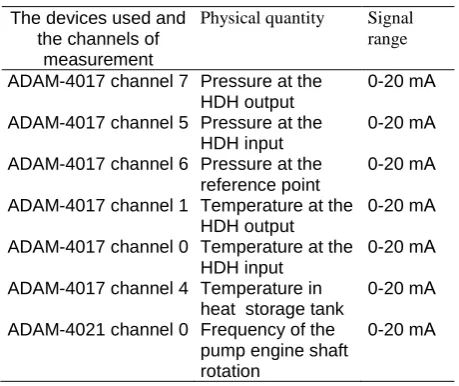
In the ECAH information-measuring system there are devices of the ADAM series intended for remote data collecting and managing. Table 4 shows the nomenclature of the involved devices of the ADAM series and physical quantities measured during the experimental studying of the ECAH energy characteristics.
Table 4. The AFAM series devices and physical quantities measured
The devices used and the channels of
measurement
Physical quantity Signal range
ADAM-4017 channel 7 Pressure at the HDH output
0-20 mА
ADAM-4017 channel 5 Pressure at the HDH input
0-20 mА
ADAM-4017 channel 6 Pressure at the reference point
0-20 mА
ADAM-4017 channel 1 Temperature at the HDH output
0-20 mА
ADAM-4017 channel 0 Temperature at the HDH input
0-20 mА
ADAM-4017 channel 4 Temperature in heat storage tank
0-20 mА
ADAM-4021 channel 0 Frequency of the pump engine shaft rotation
0-20 mА
To carry out the experiment for finding an energy-efficient mode of controlling the parameters of the pump unit using the frequency-controlled electric drive, the multifactor experiment planning method implemented with
respect to the HDH has been used [11]. In accordance with the plan of research, the value of the working fluid pressure at the inlet pipe of the HDH within the entire experiment must correspond to the established parameters according to the planning matrix [11].
To carry out the research tasks, two series of 3 to 5 experiments have been performed for various HDH specimens with different geometric parameters (Table 5) and trends have been constructed according to the experimental data.
Table 5. Initial data for the experiments
Experiment series
Working fluid pressure at the HDH inlet pipe, МPа
Frequency of the pump unit rotation, %
Experiment duration, h
1 0,60 100 1.5
2 0,50 80 2
Analyzing the trend of the working fluid pressure at the inlet pipe of the turbocharger obtained in the experimental studies on the first line of Table 5, it can be said that the initial pressure value could not be retained during the entire experiment. This is explained by the following. During the experiment the working fluid (water) is heated and, as a consequence, its properties change. It is also necessary to take into account the presence in the ECAH design of an expansion tank that takes over the excess volume of the heat carrier that is formed as a result of thermal expansion of the working fluid.
During the series of experiments the pumping unit worked at the maximum speed of 100%. The maximum frequency was selected in order to ensure the maximum effective mechanic activation of the working fluid in the HDH. At this, heating the working fluid from 20 °C to 70 °C was ensured within 60 minutes.
In the final processing of the results it has been found that the pressure drop at the inlet port of the HDH impacts the temperature drop in the flowing part of the HDH which leads to decreasing the energy efficiency of the unit. Thus, for example, in two experimental HDH specimens with the pipe reactor length of 1500 mm, the temperature difference varied from 2.7 °C at the beginning of the experiment to 1.3° C at the end (Figure 5).
Figure 5. The difference in the temperature of the working fluid as it passes through the flow part of the
HDH in the first series of experiments without maintaining the preset pressure at the pump unit
rotation speed of 100%
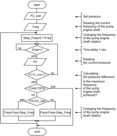
To control the speed of the electric motor of the pump unit the correction algorithm has been developed and implemented in the SCADA system in the function of pressure change (Figure 6). The correction is carried out by sending a control signal through channel 0 of the ADAM-4021 device (Table 4). As a result, the operating frequency of the electric drive of the pump unit and the pressure generated are changed. On the ECAH the pressure sensor mounted at the inlet port of the HDH measures and sends to the SCADA system the amount of pressure generated through channel 5 of the ADAM-4017.
Figure 6. Algorithms of correcting the pump unit
engine shaft rotation frequency
After analyzing the obtained experimental trends of the working fluid pressure at the inlet pipe of the HDH, while maintaining the preset pressure value at the pump speed of 80%, it was found that the pressure value throughout the entire experiment was stably maintained at the same level.
In this group of experiments the temperature difference in the flow part of the HDH varied from 2.5 °C at the beginning of the heating cycle to 2.8 °C with heating the working fluid to 30 °C, and as the working fluid was heated to 70 °C, it decreased to 2.2 °C, but in the whole it was kept at the constant level of about 2.5 °C due to stabilization of the preset pressure level at the inlet pipe of the HDH (Figure 7). The time of heating the working fluid from 20 °C to 70 °C was 105 minutes.
Figure 7. The temperature difference of the working
fluid as it passes through the flow part of the HDH in three experiments with programmed maintenance of
the preset pressure at the 80% pump speed
5.1. The results interpolation
Based on the results of the experiments for determining the energy-efficient algorithms for controlling the speed of the electric drive of the pump unit, the following conclusion has been made. Maintaining constant maximum working fluid pressure at the inlet pipe head of the pump by changing the speed of the engine shaft of the pump unit ensures the maximum effective mechanic activation of water in the gas generator with releasing the excess heat within an acceptable period of time.
As a result of experiments at a lower frequency of the pump unit, a significant reduction of energy consumption of the unit was revealed, while maintaining the temperature drop of 2.5 °C in the flowing part of the HDH. This is sufficient for achieving the working fluid temperature of the order of 70-90 °C. When the speed of the electric drive decreases from 100% to 80%, the energy consumed by the pump decreases to 45%. At this, heating the working fluid from 20 °C to 70 °C is slower than at the pump speed of 100%: 100-105 minutes against 60 minutes.
(i) at the initial start-up it is necessary to ensure the maximum speed of the electric drive, that is to implement the forced start of the system;
(ii) in the future, in order to maintain the comfort temperature of the coolant in the system for minimizing energy costs and extending the pump unit life, it must be operated at a reduced speed of the electric drive of the pump unit.
6. Conclusion
The ECAH with a hydrodynamic heater has its niche in the systems of decentralized heat and hot water supply. The HDH that is a part of the ECAH, has certain advantages: absence of water treatment and expensive heat exchange equipment, electric chemical corrosion, etc. But a significant disadvantage of this kind of heaters is considerable energy consumption by the electric drive of the pumping unit. However, it is possible to increase the energy efficiency of the ECAH complex by applying a controlled electric drive for its control. The appropriate algorithms for controlling the electric drive have been developed. In the experimental studies of the ECAH energy savings of 8% have been obtained owing to the cyclic operation, and up to 45% due to controlling the pump unit capacity. The latter can be carried out with the help of frequency control according to the previously revealed algorithms of the ECAH complex operation under changing operating conditions.
References
[1] Bloess, A., Schill, W.-P., Zerrahn, А. (2018). Power-to-heat for renewable energy integration: A review of technologies, modeling approaches, and flexibility potentials. Applied Energy 212 (2018): 1611–1626.
[2] Fernández, F.J., Folgueras M.B., Suárez I. (2017). Energy study in water loop heat pump systems for office buildings in the Iberian Peninsula 4th International Conference on Energy and Environment Research, ICEER 2017, 17-20 July 2017, Porto, Portugal.
[3] María Herrando, Christos N. Markides (2016). Hybrid PV and solar-thermal systems for domestic heat and power provision in the UK: Techno-economic considerations.
Applied Energy 161 (2016) 512–532.
[4] Zheng X., et al. (2017). Optimization based planning of urban energy systems: Retrofitting a Chinese industrial park as a case-study. Energy 139 (2017) 31-41.
[5] Osipenko S.B. On the coefficient of efficiency: Electronic resource].URL:http://www.afuelsystems.com/arhdoc./400% 25.pdf (date of the address on February 14, 2018).
[6] Shastoon, V., Kovalenko, V. and Ichenko, O. (2010). Тechnology which keeps energy and provides heat with the use of hydrodynamic heat generators. News of the Dnipropetrovsk State Agrarian and Economic University, 2010, Iss. 1. DSAEU. Dnepropetrovsk; 2010. p.88-91 [7] Kalinin, A., Kuchin, V. and Yurchenko, V. (2015).
Experimental studies of the energy characteristics of experimental industrial installations for environmentally clean hydrodynamic heaters of liquid media: Monograph. Karaganda: KSTU, 2015. 78 p. ISBN 978-601-296-932-0.
[8] RK patent No. 31624, МПК F24J 3/00 (2006.1), F24H 1/10 (2006.1), F24D 15/00(2006.1). Cavitation-vortex heat generator. V. Kuchin (KZ); I. Breido (KZ); V. Issayev (KZ); A. Kalinin (KZ); V. Yurchenko (KZ). No. 2014/1800.1; appl. 04.12.2014; publ. 30.09.2016, Bull. No. 12; 2016.
[9] Kalinin, A., Breido, I., & Zyuzev, A. (2017). Experimental studies of the frequency-controlled electric drive of a pump unit of an electric technical complex for autonomous heat supply. University Proceedings. No. 4 / Karaganda State Technical University. - Karaganda, 2017, p. 128-134.
[10] WHAT IS GENESIS32?
http://www.iconics.com/Home/Products/HMI-SCADA/GENESIS32.aspx). Accessed online February 2018. [11] Breido, I., Kalinin, A., & Karasev, N. (2016). Parametric
optimization of the design elements of the HDH by experiment planning methods. Monograph. Karaganda: KSTU Publishing House, 2016, 118 p. ISBN 978-601-315-234-9.
[12] Data Sheet: Wilo-Multivert MVIE 1607-6 (3 ~ 400 V, EPDM) [Electronic resource]. URL: http://www.wilo.com (circulation date is March 24, 2015).