https://doi.org/10.5194/ms-9-389-2018
© Author(s) 2018. This work is distributed under the Creative Commons Attribution 4.0 License.
detasFLEX – A computational design tool for the
analysis of various notch flexure hinges based
on non-linear modeling
Stefan Henning, Sebastian Linß, and Lena Zentner
Compliant Systems Group, Technische Universität Ilmenau, Ilmenau, 98693, Germany
Correspondence:Stefan Henning ([email protected])
Received: 10 August 2018 – Revised: 25 October 2018 – Accepted: 29 October 2018 – Published: 20 November 2018
Abstract. Notch flexure hinges are commonly used in compliant mechanisms for precision engineering
appli-cations and yet important rotational properties of a hinge like the bending stiffness, maximum angular deflection and rotational precision are difficult to predict accurately and simultaneously. There exist some closed-form equations and a few design tool approaches for calculating flexure hinges with particular geometries, but apart from that no comprehensive calculation program for the contour-specific analysis is known to the authors. Devel-oped in MATLAB, this paper presents a novel computational design tool using a non-linear analytical approach for large deflections of rod-like structures to calculate the elasto-kinematic flexure hinge properties by numeri-cally solving a system of differential equations. Building on previous investigations, four certain hinge contours are implemented, the circular, the corner-filleted, the elliptical, and the power function-based contour with dif-ferent exponents. In addition to the theoretical approach and the implementation it is exemplarily shown, that finite elements method (FEM) results correlate well with the analytical design tool results. For a given deflection
angle of 10◦ and a corner-filleted contour as an example, the deviations of the bending stiffness are between
0.1 % and 9.4 % for typical parameter values. The presented design tool can be beneficial for the accelerated and systematic synthesis of compliant mechanisms with optimized flexure hinges.
1 Introduction
Notch flexure hinges experience a growing application in industry and research. Due to their advantages of high re-producibility, high resolution, and clearance-free or friction-less motion they are widely used in compliant mechanisms (Howell et al., 2013; Zentner, 2014) for precision engineer-ing, micromechanics or measurement technology tasks. For these applications flexure hinges with specific notch geome-tries are the most common form of compliant segments used to realize a rotation (Lobontiu, 2003). According to bend-ing of the materially coherent joint, the angular deflection is limited because of the resulting maximum strain. Further, a small shift of the axis of rotation results which affects the motion behavior as well as guidance accuracy of a compliant mechanism over its rigid-body counterpart (Venanzi et al., 2005).
graphs may be used to figure out an appropriate order for polynomial flexure hinges (Linß, 2015).
To date specific tools for the analysis of flexure hinges are sparsely found. One author for example provides scripts that can be downloaded and used within MATHCAD to calcu-late flexure hinges and compliant mechanisms using simpli-fied design-equations in a limited parameter range (Janssen, 2018). Other software-based applications for the analysis of circular notch flexure hinges are coming with a simple graph-ical user interface (Vink, 2018; van Beek, 2018). Addition-ally, inaccessible applications which are developed for pub-lished research are reported briefly (Ivanov, 2016). Most of these applications are based on the implementation of em-pirical design equations derived from analytical considera-tions or FEM analysis. When analyzing flexure hinges us-ing these tools, the analyzus-ing options are mostly very re-stricted. Most of these tools apply compromised design equa-tions only within a small parameter range. Apart from that, more complex tools for the analysis (Megaro et al., 2017) and synthesis (Turkkan and Su, 2016; Culpepper and Kim, 2004) of compliant mechanisms with distributed compliance are state of the art. On the contrary they do neither offer the possibility to regard several notch flexure hinges nor calcu-late the rotational precision or axis shift. Moreover, it has to be mentioned that some of these software applications re-quire licenses for commercial software like MATHCAD or MATLAB, but others are available for free. With this paper the authors try to fill the gap regarding a comprehensive soft-ware application for the accurate and non-linear analysis of various notch flexure hinges with the most important con-tours and broad evaluation criteria which may be advanta-geous especially for precision engineering to enable an intu-itive and quick design process.
According to a plane rotation caused by bending due to a moment or transverse force load, this paper presents a novel design tool for the contour-specific quasi-static anal-ysis of notch flexure hinges. The tool offers the calculation of parameters like bending stiffness, rotational axis shift, maximum elastic strain and outer fiber strain distribution, maximum angular deflection, and deformation of the neu-tral axis for extensive geometric specifications – computable for a specified load or rotational angle. The calculations will be possible by numerically solving a system of differen-tial equations for large deflections of thin rod-like structures within a few seconds. Further, the design tool provides a plot of the hinge for the given geometry.
The following sections are organized as follows. In Sect. 2 the investigated types and regarded contours of flexure hinges are presented and characterized. In Sect. 3 the analyt-ical approach for the characterization of flexure hinges with the theory of large deflections of rod-like structures based on non-linear modeling is described. Moreover, specific param-eters to calculate the motion and strain are investigated, too. In Sect. 4 the development and implementation of the design tool are outlined. Also, the algorithm for the analyzing
proce-dure is illustrated. In Sect. 5 an FEM-based characterization is done for four different hinge contours and results are com-pared to the design tool-based solution. Finally, conclusions are drawn in Sect. 6.
2 Design and modeling of notch flexure hinges
In the past numerous designs of flexure hinges with no limit to the geometric shape have been developed. It can mainly be differentiated between cut-out geometries and more com-plex compositions of the compliant segment. An example for a complex geometry would be the proposed butterfly hinge (e.g. Henein et al., 2003; Pei and Yu, 2011) or a topology optimization-based contour (Zhu et al., 2014). However, in this paper the focus is on notch flexure hinges with distinct contour shapes. For this purpose, many notch geometries are being outlined in literature. By far the most commonly used and easy to manufacture circular flexure hinge contour (e.g. Paros and Weisbord, 1965; Wu and Zhou, 2002) is well known for its large bending stiffness and high precision but also for high maximum strain values. On the contrary, a well distributed strain can be achieved with the corner-filleted contour (e.g. Lobontiu, 2003; Meng et al., 2013). As a com-promise between high precision and low strain the elliptical contour has been applied (e.g. Smith et al., 1997; Chen et al., 2008). Moreover, parabolic or hyperbolic (e.g. Lobontiu, 2003; Chen et al., 2009) and cycloidal contours (Tian et al., 2010) have been utilized as well as combinations of the men-tioned basic geometries (e.g. Zelenika et al., 2009; Lobontiu et al., 2011; Chen et al., 2011).
Beyond that, more complex mathematical functions like the spline contour (Christen and Pfefferkorn, 1998; De Bona and Munteanu, 2005), the power function-based contour (Li et al., 2013) the exponent-sine contour (Wang et al., 2013) the Lamé contour (Desrochers, 2008) and the Bézier contour (Vallance et al., 2008) are rarely taken into consideration. Lately higher order polynomial functions were proposed to regulate the bending stiffness, precision and elastic strain dis-tribution to an optimum (Linß et al., 2011a, 2015; Gräser, et al., 2018). For combining the advantages of different notch contours, asymmetric flexure hinges were previously consid-ered (Chen et al., 2005). Also the kinematic behavior in terms of an ideal axis of rotation can be realized with asymmetric flexure hinges (Linß et al., 2011b; Lin et al., 2013). However, in this paper only transversal and axial symmetric notch flex-ure hinges are investigated because they allow a holistic and intuitive design with regard to the mechanism synthesis. The investigated design and modeling of notch flexure hinges are described in the following subsections.
2.1 Investigated flexure hinges and geometric parameters
Contour design domain
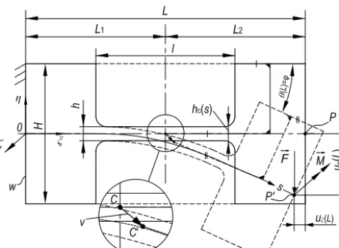
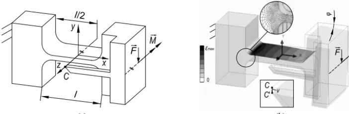
Figure 1.Notch flexure hinge with a variable hinge height within
the contour design domain, the geometric parameters and the de-flected state as a result of a moment and/or a transverse force load.
initial and the deflected state. With respect to the application in a mechanism and according to literature, the flexure hinge with its notch contour design domain is generally modeled with adjacent link segments (Yong et al., 2008). The deflec-tion can be modeled in two ways by either specifying the load
(a moment loadM, a transverse force loadF, or a moment
and force loadM,F) or by specifying the deflection angleϕ
at the free end in pointP. The illustration of the flexure hinge
in Fig. 1 shows the basic geometric parameters that define the
shape of the hinge: the total hinge heightH, minimum hinge
heighth, hinge widthw, total lengthL, contour lengthl, and
contour functionhc(x) based on the selected notch geometry.
In this paper only directionally constant forces are ac-counted and the equations are based on them. The system of differential equations will vary for follower forces and may be adjusted for those applications. The vectorial
direc-tion for a given moment isM= −Mez, for a transverse force
F = −Feyand for the bending angleϕ= −ϕez. For
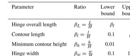
charac-terizing different flexure hinges, the dimensionless ratios in Table 1 are introduced with their lower and upper bounds in the software application. These lower and upper bounds are chosen to aim for that the dimensions of the cross sections are small compared to the hinge length and therefore to support the validity of the implemented theory incorporating rod-like structures.
2.2 Flexure hinge contour selection and definition
Regarding Fig. 1, the design domain for the variable notch
contour ranges from point D1 toD5along thex-axis while
the contour will always be axial-symmetric to they-axis. Due
to the used theory for all investigations it must be assured that the hinge contour is a symmetric, continuously differ-entiable, and not undercut contour function. The hinge has a
rectangular cross-section, and the minimum notch heighthis
at the origin of the hinge (atx=0). In some occasions, the
Table 1.Geometric flexure hinge parameters related to the total
hinge height and their parameter ranges.
Parameter Ratio Lower Upper
bound bound
Hinge overall length βL= HL βl 10
Contour length βl=Hl 0.1 βL
Minimum contour height βh=Hh 0.01 1
Hinge width βw=Hw 0.1 100
contour will contain a straight line parallel to they-axis in
betweenD1andD2and analogically in betweenD4andD5,
and therefore the resulting curvature will include a discon-tinuity. With this regard, the integration when solving will
be performed ranging from the pointsD2 to D4 to ensure
a continuously differentiable mathematical expression. This can be done by adjusting the initial value of the curvature for each segment when a discontinuity is present.
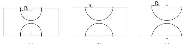
In the design tool three typical flexure hinge contours are considered, the circular (Fig. 2a), corner-filleted (Fig. 2b) and elliptical contour (Fig. 2c). Besides that, the advantages of the polynomial contour (Linß et al., 2011a) are implemented and extended to a power function (Fig. 2d) to offer a wider range of possible contours. The power function-based hinge contour offers a great spectrum for the flexure hinge design (Linß, 2015). Due to the variable height function, the contour design may be adjusted from circular-type to corner-filleted-type contours to achieve a desired angular deflection or axis shift.
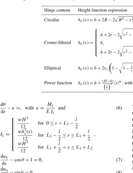
In Table 2 the according height functions of the four im-plemented flexure hinge contours are listed. Contour-specific parameters for the exact definition of each flexure hinge are
proposed withR,r, rx,ry,n as they are shown in Fig. 2.
The circular and elliptical flexure hinge contours may be ex-act or approximated semi-circles or semi-ellipses depending on the chosen geometry. This issue is depicted in Fig. 3 for the circular hinge contour and in Fig. 4 for the elliptical con-tour. The circular hinge contour only describes an exact
semi-circle for 2R≤H−h(cf. Fig. 3a and b). The notch length
in these two cases results as:
l=2R. (1)
Otherwise the circle center is positioned outside of the con-tour design domain (cf. Fig. 1) and approximated semi-circles result (cf. Fig. 3c) with the notch length expressed as:
l=2
s
R2−
H−h
2 −R
2
. (2)
The same accounts for the elliptical contour. An exact
(a) (b) (c) (d)
(a) (b)
Figure 2.The four implemented flexure hinges with their contour-specific parameters:(a)circular contour with radiusR,(b)corner-filleted
contour with stress-optimal fillet radiusr=0.1l(Linß et al., 2011b),(c)elliptical contour with major axisrxand minor axisry,(d)variable
power function-based contour (shown for different exponent valuesn).
(a) (b) (c)
Figure 3.Three different cases for designing a circular flexure hinge in dependence of the input parameter values (all shown forβL=2 and
βh=0.1):(a)2R < H−h(withβl<1),(b)2R=H−h(right semi-circular contour, withβl<1),(c)2R > H−h(with 0< βl< βL).
and b) and the notch length is as follows:
l=2rx. (3)
In case the ellipse center is located outside of the contour de-sign domain, approximated semi-ellipses arise with the notch length as:
l=2rx
s
1−
H−h
2ry
−1
2
. (4)
3 Theoretical approach
In contrast to form and force-closed joints the materially co-herent connection of flexure hinges leads to a restoring force when bent (bending stiffness) – which can be advantageous in technical systems, too. Apart from that, the angular de-flection of a flexure hinge is limited by reaching admissi-ble material stress or strain values (maximum angular deflec-tion). Moreover, no exact relative rotation is possible with a flexure hinge because always a shift of its axis of rotation occurs in dependence of geometric and load parameters (ro-tational precision). When applying flexure hinges in a com-pliant mechanism, this can lead to path deviations compared to the rigid-body mechanism, which are not negligible espe-cially in precision engineering (Venanzi et al., 2005; Linß, 2015).
In this section, the approach of the non-linear analytical characterization of a notch flexure hinge and the equations for its bending stiffness, strain distribution/maximum angular elastic deflection, and rotational precision are presented.
3.1 Theory for large deflections of rod-like structures
As long as the dimensions of a cross section are small com-pared to the rod length, the non-linear theory for large de-flections of rod-like structures is sufficient to describe the motion behavior of compliant systems (Zentner, 2014). If a flexure hinge is modeled together with adjacent deformable link segments as a bent beam with a variable height, this the-ory is assumed to be suitable for the calculations in this pa-per, too. Therefore, the assumption is made that Bernoulli’s hypothesis, Saint-Venant’s principle, and Hooke’s law apply. Shear deformation according to Timoshenko as investigated in (Dirksen and Lammering, 2011) and the effect of anticlas-tic bending (Campanile et al., 2011) are neglected, because first investigations with the applied theory show a good cor-relation between the theoretical results and FEM simulations for different flexure hinges (Linß et al., 2017b).
A stationary coordinate systemξ ηζis considered with the
origin at the fixed end (Fig. 5). Bending of a beam results in a deflection curve of the neutral axis with assumed constant
length. Therefore, the arc length parametersis introduced to
describe the neutral axis in its deflected state. The rod under-goes a shiftuξ(s) anduη(s) for each point alongs. Because of
the shift inξ andη-direction a deflection angleθ(s) results.
The resulting curvature is defined byκ(s) as the gradient of
the deflection angleθ(s). Thus, for describing a flexure hinge
as a bent rod or beam four non-linear differential equations result:
dMζ
(a) (b) (c)
1
Figure 4.Three different cases for designing an elliptical flexure hinge in dependence of the input parameter values (all shown forβL=2,
βh=0.1 with 0< βl< βL):(a)2ry< H−h,(b)2ry=H−h(right semi-elliptical contour),(c)2ry> H−h.
Table 2.Height functions of the four implemented flexure hinge contours.
Hinge contour Height function expression
Circular hc(x)=h+2R−2pR2−x2
Corner-filleted hc(x)=
h+2r−2
r
r2−x+l
2−r 2
, for −l
2≤x <−2l +r
h, for−l
2+r≤x≤2l−r
h+2r−2
r
r2−
x−2l +r
2
, for 2l −r < x≤2l
Elliptical hc(x)=h+2ry
1−
r
1−x2
rx2
Power function hc(x)=h+(H−h)
l
2
n|x|n;withn∈Rand 1.1≤n≤50
dθ
ds −κ=, with κ=
Mζ
E Iζ
and (6)
Iζ=
wH3
12 for 0≤s < L1−
l
2
wh3c(s)
12 for L1−
l
2≤s≤L1+
l
2
wH3
12 for L1+
l
2< s≤L1+L2
,
duξ
ds −cosθ+1=0, (7)
duη
ds −sinθ=0. (8)
Since the flexure hinge is symmetric, no initial curvature of the beam is regarded in this paper. Due to the fact that simple and concise closed-form equations cannot be derived from this system of non-linear differential equations a numerical solution is done with the following boundary conditions for a moment load at the free end of the hinge:
κ(L)= M EIζ(L)
, θ(0)=0, uξ(0)=0, uη(0)=0, (9)
and for a transverse force load with:
κ(L)=0, θ(0)=0, uξ(0)=0, uη(0)=0. (10)
The boundary value problem is solved numerically with the use of MATLAB as it is described in Sect. 4.2. At the end
of this procedure all four parametersκ,θ,uξ anduηare
ob-tained for each points along the deformed neutral axis and
further results can be determined as it is described in the fol-lowing subsections. Please note, though the equations have been derived for a universal approach based on a positive deflection, the input force, moment or deflection angle are translated into negative values by the software. This way the
flexure hinge is always deflected intoηandξ-direction like
depicted in Fig. 5. Nevertheless, because of the symmetry, it makes no difference in which direction the hinge is deflected. Therefore, it is focused on the absolute value of the angular deflection.
3.2 Bending stiffness of a flexure hinge
On the contrary to the compliance of a flexure hinge, the bending stiffness around an axis of a system of coordinates is a measure for the resistance of an object against deforma-tion under external loads. Due to the fact that flexure hinges
in this paper are mainly exposed to bending around theζ
Figure 5.Parameters for the theoretical characterization of a
flex-ure hinge (depiction of the initial and deflected position) with the model for the determination of the rotational axis shift based on guiding the center with a constant distance, the fixed center ap-proach.
by material and geometric parameter changes. When speak-ing about bendspeak-ing stiffness properties in this paper, depend-ing on the load case the relation between the load and the
rotation angle,M(ϕ) andF(ϕ), are meant.
3.3 Strain distribution and maximum angular deflection of a flexure hinge
The bending stressσ is analyzed after linear beam theory to
characterize the maximum stress of the entire flexure hinge for a given deflection angle as a result of the moment or force load:
σ(s)|η
max= −
Mζ(s)
Iζ(s)
·ηmax(s). (11)
According to the used theory, the maximum absolute stress value always results at the outer fiber for the maximum
coor-dinate ofη, which corresponds with the contour height
func-tion of the flexure hinge. Fulfilling Hooke’s law, stress and strain are linearly connected by the Young’s modulus as it is
described for the bending strainεas:
ε(s)=σ(s) E = −
Mζ(s)
EIζ(s)
·ηmax(s)= −κ(s)·ηmax(s). (12)
Further, a part of Eq. (12) can be expressed with the
curva-ture κ(s). Due to the solution of the system of differential
equations in MATLAB the curvature along the neutral axis is known and can therefore be used to determine the elas-tic strain. This solution is obtained for each specification and load case of the analysis settings. The maximum elastic strain can then be found with an accuracy that depends on the step
size of the solution forκ(s). According to the approach, the
maximum strain is independent from the widthwfor a given
deflection. Due to the used theory, only the bending moment
Mζ is taken into account.
For a moment load, the maximum strain occurs, related
to theξ-axis in the hinge center in general. In contrast to
this, for a force load the critical location depends on the flexure hinge contour. For this purpose, the strain distribu-tion can be plotted along the entire flexure hinge so that a user can assess critical strain areas. The maximum absolute
value of the strainεmax is implemented in the results
win-dow of the design tool. Among the four regarded contours, the circular contour always leads to the highest strain values for a constant deflection (see Sect. 5). Using the elliptical, the power function-based, and the corner-filleted contour, the maximum strain value can be further reduced and analyzed with the software for different material choices. The
admissi-ble elastic strainεadmshould always be higher than the
max-imum strain of each flexure. A safety factor is introduced to emphasize the relation between admissible and maximum elastic strain according to Eq. (13):
SF=εmax
εadm (13)
The user should always aim for a safety factor SF>1 to
ensure that no plastic deformation arises. Using the calcu-lated safety factor, the maximum angular deflection can be expressed by Eq. (14):
ϕmax=SF·ϕ (14)
Therein ϕ will either be the user-defined deflection angle
or the calculated deflection angle in case a load is given. This way the contour and geometry-dependent correlation
between the material-given admissible elastic strainεadmand
the maximum rotation angleϕmaxis derived.
3.4 Rotational precision of a flexure hinge
Due to the fact that flexure hinges do not have a stationary rotation axis, the term rotational precision is introduced. No-tably, in precision engineering, the rotational precision of a flexure hinge is a very important performance criterion. Be-cause of the serial connection of several flexure hinges in the kinematic chain of a compliant mechanism, the rotational
axis shiftvof a single flexure hinge (cf. Fig. 5) can influence
the path deviation of a coupler point of the compliant mecha-nism compared to the rigid-body mechamecha-nism. Depending on the possibility to specify the deflection angle or load case,
v(ϕ) orv(M, F) is considered in this paper. In literature
sev-eral approaches are suggested to express the rotational preci-sion which lead to slightly different results. Most approaches are based on the deflected state of the hinge so that the shift of
the center point atξ=L
2 is calculated (e.g. Lobontiu, 2003;
Tian et al., 2010). Another approach considers the
throughP0. This way the axis shift can be determined inξ
-direction only (e.g. Horie et al., 1997; Smith, 2000). Further, the fixed centrode is calculated with the help of a geomet-rical approximation method (e.g. Dirksen and Lammering, 2011; Palmieri et al., 2012), which leads to high numerical effort because of a theoretically infinitesimal analysis. As it has been described in previous publications (e.g. Tseytlin, 2002; Zelenika et al., 2009; Linß et al., 2011b), the distance
between the initial center pointCand the guided center point
C0 with a constant distance ofL2during the motion (fixed
center approach) is suitable and chosen to define the
rota-tional precisionvin this paper (cf. Fig. 5).
The absolute value of the rotational axis shiftv, based on
the fixed center approach, is put together from the axis shift
inξ andη-direction as:
v=
q
(ξC0−L1)2+η2
C0 =
q
L2+uξ−L2cosϕ2+ uη−L2sinϕ2. (15)
To determine the axis shift according to Eq. (15), the
coordi-natesξ andηat the free end of the hinge on the neutral axis
sand the rotation angleϕmust be known. The numerical
so-lution of the system of differential equations provides results
for all s in both axes shifts so the coordinates of pointP0
are known, too. The deflection angleϕ will therefore equal
the angular deflection in pointP0which is derived from the
differential equation ofθ(s) usingϕ=θ(L).
Furthermore, to minimize the axis shift, the user should know, that independent from the hinge contour a transverse force leads to a significant larger axis shift than a moment
load for the same angleϕ. Also the hinge contour has a strong
influence on the axis shift, depending on the dimensionsβl
and especiallyβh (e.g. Linß et al., 2017a). With regard to a
high rotational precision or a small axis shift the following order can be generalized for thin hinges: The circular con-tour, the elliptical contour or polynomial 4th-order concon-tour, and the corner-filleted contour. It can be concluded that the more the compliance is distributed along the hinge contour (meaning longer thin stretches), the higher the axis shift will be. On the contrary, a more concentrated compliance leads to a better rotational precision.
4 Implementation
In this section the development of a computer program for the analysis of notch flexure hinges with different hinge con-tours will be described. For this purpose, the previously de-scribed theory for large deflections of rod-like structures will be implemented in a graphical user interface (GUI) devel-oped with MATLAB. Therefore, a solution for the non-linear analytical characterization will be received and evaluated. In the following subsections it is shown how the different in-puts and selections are realized throughout the GUI (front end) and how they are internally processed by the software
(back end) to produce the results which are then displayed in fields and diagrams. Further it is explained how the soft-ware will be distributed for license-free public usage. For the development of the GUI the MATLAB version R2017b was used.
4.1 Matlab-based graphical user interface
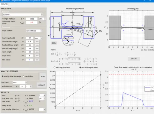
The developed GUI for the analysis of notch flexure hinges is shown in Fig. 6. For public usage it was generated as a standalone application called “detasFLEX” using the MAT-LAB deploy tool for WINDOWS 64 bit computers. Due to this process, no MATLAB license is needed to run the pro-gram. Although, the file comes with a Runtime – a database including all the important MATLAB functions – that needs to be downloaded and installed to the computer.
The development of the GUI has been made with the use of the GUI development environment, called GUIDE. It ba-sically is a layout editor where one can graphically design the appearance of an application using input and output text fields, push buttons, sliders, axes and more. GUIDE automat-ically generates the MATLAB code for modifying the pro-gram behavior. This way it is possible to process input data, solve the system of differential equations and generate all re-sult data and diagrams.
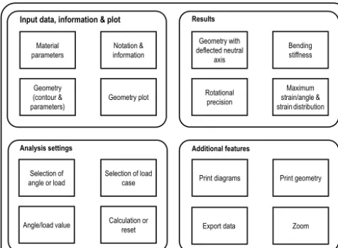
4.2 Program structure
For a better overall understanding for a user to analyze a spe-cific flexure hinge using the given design tool, the modular composition of the program is shown in Fig. 7 which can be derived from the GUI in Fig. 6. Mainly the interface is di-vided into four groups. To start with, there are text fields for the input of data and information about the hinge notation and valid geometries for the chosen contour. In this area the material, the hinge contour, the dimensional and the contour-specific geometric parameters of the flexure hinge may be set. Next the analysis settings can be made. Thereby the pro-gram user can choose between the selection of a given de-flection angle or a given load and specify its value, set the load case and finally press the “calculate”-button or reset ev-erything to default values. Afterwards, when all results are obtained by the solver, the result values are presented in a separate section of the interface. Also, the geometry, bend-ing line, bendbend-ing stiffness and precision as well as the strain distribution are charted in diagrams. In addition, features to export data and diagrams into files, print the geometry and zoom into the notation are provided.
Figure 6.Graphical user interface of the PC program detasFLEX (design tool for the analysis of flexure hinges), shown using the example
of a corner-filleted flexure hinge.
a contour and manipulate contour specific parameters. These values and selections get read and converted into SI units for further processing. To make sure all input data comply with the geometric bounds and are numeric real positive data greater zero, a query is programmed. In the case of invalid inputs, a warning will be displayed and parameters need to be adjusted by the user. Following, a constant step size along
−L1≤x≤L2is being set astc=L×10−3for the
calcula-tion and plotting of the flexure hinge geometry. Afterwards, the program determines if either the deflection angle or the load at the free end of the flexure hinge is specified which reflects major differences between the solution.
In case a deflection angle is specified, firstly the angle value is divided into five load steps. It has been shown that the motion behavior for very large angular deflections may accurately be calculated with the used theory (Zentner et al.,
2017) which is why the angle was limited toϕ≤45◦.
There-after, the chosen load case (moment or force) needs to be evaluated. Next, initial values are estimated. In a following
step, the initial guess is approximated for a cantilever beam,
fixed atξ=0 with the constant heighthand a deflection of
ϕ(L)=1◦ because the extent of the deflection mainly
de-pends on the minimum notch height and so the solver does not exaggerate the deflection on the first adjustment step. The initial guesses are derived from linear beam theory for small deflections and result for a moment load as
Mini=1◦· π
180◦·
Ewh3
12(L1+L2), (16)
and for a force load results as
Fini=1◦· π
180◦·
Ewh3
6(L1+L2)2. (17)
Input data, information & plot Results
Additional features Material
parameters informationNotation &
Geometry (contour &
parameters) Geometry plot
Selection of
angle or load Selection of loadcase
Angle/load value Calculation orreset
Geometry with deflected neutral
axis
Rotational precision
Maximum strain/angle & strain distribution
Print diagrams Print geometry Bending stiffness
Export data Analysis settings
Zoom
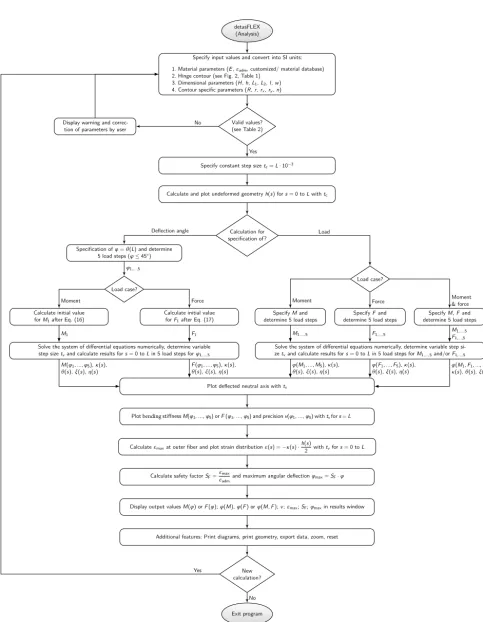
Figure 7.Modular structure of the PC program detasFLEX
(Anal-ysis).
gets solved with the used MATLAB functionode45with a
variable step size tv for efficient calculation. The solver is
based on the Dormand-Prince method which uses six func-tion evaluafunc-tions in each step. It represents an explicit four-step Runge-Kutta method. The algorithm performs an itera-tive integration of first order non-stiff differential equations with initial conditions. Afterwards a solution is obtained for the system of differential equations. In case of a force load, a boundary value problem is present because of the unknown
support reaction due to theξ-shift of the free end (important
for large deflections). For this purpose, the function fsolve
(shooting method for the unknown moment support reaction
calledMAζ) is applied to iterate the solution until the
bound-ary conditions are matched. In case of a moment load no op-timization needs to be done because all support reactions are
explicit. It can be taken advantage of the linear relationM(ϕ)
so that the system of differential equations only needs to be
solved numerically forMini (usingode45) and with the
re-sulting angle θ(L)=ϕ the related moment M(ϕ) may be
obtained. Resulting values of the results M or F, ϕ,κ,θ,
uξ anduηare then being saved for further processing. It can
be mentioned, that the elapsing time for the numerical solu-tion is usually shorter for plain moment loads because of the simplifications possible.
In a following step, when a solution for the system of dif-ferential equations was found, the deflected state of the neu-tral axis is plotted into the diagram. Also the bending stiff-ness and axis shift are evaluated with the given equations described in Sect. 3 and outlined in their respective chart. Next, the outer fiber strain distribution and maximum value
are being calculated with the step sizetvand also displayed
in a graph. The safety factor and all other output values are printed into the intended results window. The whole pro-cess takes just a few seconds after the “calculate” button is pressed.
4.3 Segment-wise calculation
As it is already shown in Fig. 2, the flexure hinges are split up into several sections for the numerical solution. Beam sec-tions with a constant hinge height are solved by referring to a constant geometrical moment of inertia whilst sections con-taining a variable contour function are referred to the solu-tion of the corresponding height funcsolu-tion found in Table 2. The system of differential equations therefore varies for each section. The circular, the elliptical and the power function-based contour are split up into three sections (cf. Fig. 2a, c and d) and the corner-filleted contour is split up into five sep-arate sections when being calculated (cf. Fig. 2b). The nu-merical solution at the end of each section serves as a set of initial values for the next section. This method guarantees a continuous progression of the neutral axis. Furthermore, us-ing this approach, transition points arise at the exact location in between sections along the neutral axis which enable the evaluation of results precisely at these points. This is espe-cially important when it comes to examining the rotational precision of the regarded flexure hinge.
4.4 Examples
To demonstrate some of the functionalities the design tool offers, examples are given in this subsection. The program enables a wide variety of different geometry, material, con-tour and analysis settings selections so that numerous notch flexure hinges for diverse tasks in industry and research may be analyzed within a few seconds with respect to the geomet-ric lower and upper bounds.
The following examples are done for all four different
con-tours with the same typical geometric ratios (βL=2,βl=
1,βh=0.03,βw=0.6) and material settings (E=72 GPa,
εadm=0.5 %). Firstly a specific given deflection angle of
ϕ=5◦is defined and each hinge is then calculated for a force
load. The obtained geometry, deflection curve and strain dis-tribution diagrams are presented in Fig. 9. It becomes clear that the deflection angle is too high for the chosen circular and elliptical flexure hinge contour because the admissible elastic strain is exceeded. Further it is noticeable, that due to the load case of a force load, the maximum elastic strain is shifted out of the hinge center towards the fixed end of the hinge, the more distributed the compliance of the hinge is. This is especially significant for the power function-based contour (Fig. 9c) and even more for the corner-filleted con-tour (Fig. 9d). Also, the more distributed the compliance is along the hinge contour (larger sections with a small hinge height), the lower the maximum strain will be which is well visible for the corner-filleted contour. Also the bending line
is more equally curved throughout the whole lengthL, the
detasFLEX (Analysis)
Specify input values and convert into SI units: 1. Material parameters (E,εadm, customized/ material database) 2. Hinge contour (see Fig. 2, Table 1)
3. Dimensional parameters (H,h,L1,L2,l,w) 4. Contour specific parameters (R,r,rx,ry,n)
Valid values? (see Table 2) Display warning and
correc-tion of parameters by user
Specify constant step sizetc=L·10−3
Calculate and plot undeformed geometryh(s) fors= 0 toLwithtc
Calculation for specification of? Specification ofφ=θ(L) and determine
5 load steps (φ≤45◦)
Load case?
Calculate initial value forM1after Eq. (16)
Calculate initial value forF1after Eq. (17)
Solve the system of differential equations numerically, determine variable step sizetvand calculate results fors= 0 toLin 5 load steps forφ1,...,5
Load case?
SpecifyMand
determine 5 load steps determine 5 load stepsSpecifyFand determine 5 load stepsSpecifyM,Fand
Solve the system of differential equations numerically, determine variable step si-zetvand calculate results fors= 0 toLin 5 load steps forM1,...,5and/orF1,...,5
Plot deflected neutral axis withtv
Plot bending stiffnessM(φ1,...,φ5)orF(φ1,...,φ5)andprecisionv(φ1,...,φ5)withtvfors=L
Calculateεmaxat outer fiber and plot strain distributionε(s) =−κ(s)·h(2s)withtvfors= 0 toL
Calculate safety factorSF=εmaxεadmand maximum angular deflectionφmax=SF·φ
Display output valuesM(φ) orF(φ);φ(M),φ(F) orφ(M,F);v;εmax;SF;φmaxin results window
Additional features: Print diagrams, print geometry, export data, zoom, reset
New calculation?
Exit program No
Yes
Deflection angle
φ1,...,5
Moment Force
M1 F1
M(φ1, ...,φ5),κ(s),
θ(s),ξ(s),η(s) Fθ((sφ1),, ...,ξ(sφ5),η),(sκ)(s),
Load
Moment Force Moment& force
M1,...,5 F1,...,5 MF1,...,5
1,...,5
φ(M1, ...,M5),κ(s),
θ(s),ξ(s),η(s) φθ((sF),1, ...,ξ(sF),5),η(κs)(s), κφ((sM),1,θF(1s, ...,),ξ(Ms),5,ηF(5s),)
No Yes
Abbildung 0.1: Flowchart detasFLEX - Analysis
Figure 8.Detailed flowchart of the PC program detasFLEX.
S. Henning et al.: detasFLEX – A computational design tool for notch flexure hinges 399
Figure 2
(a) (b) (c)
Figure 3
(a) (b) (c)
Figure 4
(a) (b) (c) (d)
Figure 9
1
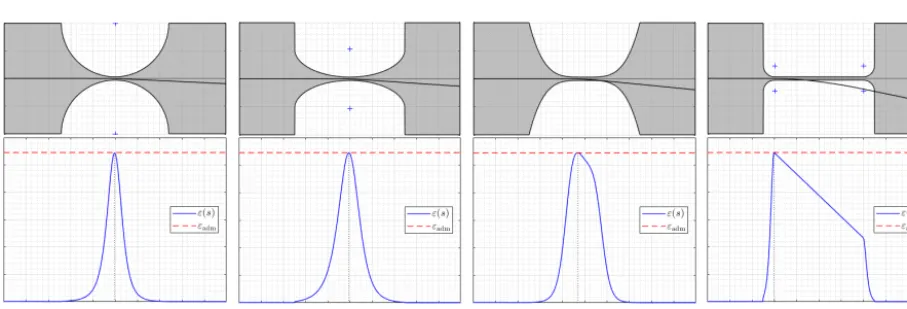
Figure 9.Example results of the deformed neutral axis and the outer fiber strain distribution for a force load computed for an angle input of
|ϕ| =5◦(βL=2,βl=1,βh=0.03; result values see Table 3):(a)circular contour,(b)elliptical contour,(c)power function-based contour
withn=4,(d)corner-filleted contour.
(a) (b) (c) (d)
Figure 10. Example results of the deformed neutral axis and the outer fiber strain distribution for different force load inputs to equal
εadm=0.5 % (βL=2,βl=1,βh=0.03):(a)circular contour with|ϕmax| =2.72◦,(b)elliptical contour with|ϕmax| =3.81◦,(c)power
function-based contour withn=4 and|ϕmax| =5.56◦,(d)corner-filleted contour with|ϕmax| =11.73◦.
In another case study, which is presented in Fig. 10, the same four flexure hinges are regarded but with different anal-ysis settings. For this application example, the maximum an-gular deflection that is derived from the previous example
is taken as an input forϕ. The maximum angular deflection
varies for each hinge in accordance to the compliance distri-bution. The circular flexure hinge (Fig. 10a) offers the lowest
possible angular deflection in this case with ϕmax =2.72◦
due to the highest bending stiffness compared to the
corner-filleted contour (Fig. 10d) withϕmax=11.73◦. Nevertheless,
the circular flexure hinge realizes the lowest shift of the axis
of rotation. When applyingϕmax, the maximum elastic strain
equals the admissible elastic strain as it is visible in the strain distribution diagrams in Fig. 10. According to the non-linear
theory the deformation of the neutral axis in ξ-direction is
obvious, especially for the corner-filleted flexure hinge (cf. Sect. 2). Design tool users may adjust the hinge contour, the dimensional or contour-specific parameters to influence the
maximum possible angular deflection, the maximum elastic strain or the rotational stiffness and precision to suit the flex-ure hinge design to their needs.
5 FEM-based verification
To confirm the analytical design tool-based results and there-fore the usability of the provided PC program, finite elements method is considered to compare and verify the implementa-tion of the non-linear deformaimplementa-tion theory. For the FEM-based 3-D structural simulation ANSYS Workbench 18.2 was used. The CAD model and FEM model are shown in Fig. 11. For the determination of the rotational precision in FEM, the same approach as it is described in Sect. 3.4 is considered by adding an additional part onto the CAD model according to the chosen fixed center approach (cf. Fig. 5) to measure
the distance betweenCandC0(Fig. 11a). The FEM model is
Table 3. FEM-based verification and comparison of the contour-specific and load-dependent results for a discrete angular deflection of
|ϕ| =5◦(βL=2,βl=1,βh=0.03,βw=0.6) with specification of the relative deviations to the analytical design tool solution.
Hinge contour Method Moment load Force load
M[Nm] v[µm] εmax[%] |ϕmax|[◦] F[N] v[µm] εmax[%] |ϕmax|[◦]
Circular withR=5 mm
analytical 0.0592 1.411 0.914 2.736 5.944 4.358 0.919 2.720
FEM 0.0622 1.428 0.892 2.803 6.240 5.020 0.894 2.796
deviation 5.1 % 1.2 % 2.4 % 2.4 % 5.0 % 15.2 % 2.7 % 2.8 %
Corner-filleted withr=0.1l
analytical 0.0098 5.485 0.151 16.534 0.987 54.675 0.213 11.727
FEM 0.0102 5.367 0.166 15.060 1.025 54.720 0.228 10.965
deviation 4.1 % 2.2 % 9.9 % 8.9 % 3.9 % 0.1 % 7.0 % 6.5 %
Elliptical, withrx=2ry=0.5l
analytical 0.0420 1.943 0.649 3.854 4.235 7.843 0.656 3.811
FEM 0.0446 1.906 0.641 3.900 4.481 8.551 0.639 3.912
deviation 6.2 % 1.9 % 1.2 % 1.2 % 5.8 % 9.0 % 2.6 % 2.7 %
Power function withn=1.5
analytical 0.1614 0.741 2.490 1.004 16.076 1.660 2.481 1.008
FEM 0.1557 0.825 2.476 1.010 15.632 2.310 2.478 1.009
deviation 3.5 % 11.3 % 0.6 % 0.6 % 2.8 % 39.2 % 0.1 % 0.1 %
Power function withn=2.0
analytical 0.0818 1.042 1.263 1.979 8.217 2.585 1.269 1.970
FEM 0.0852 1.138 1.368 1.827 8.555 3.140 1.369 1.826
deviation 4.2 % 9.2 % 8.3 % 7.7 % 4.1 % 21.5 % 7.9 % 7.3 %
Power function withn=3.0
analytical 0.0402 1.680 0.620 4.029 4.038 5.650 0.634 3.946
FEM 0.0427 1.758 0.694 3.602 4.285 6.242 0.694 3.602
deviation 6.2 % 4.6 % 11.9 % 10.6 % 6.1 % 10.5 % 9.5 % 8.7 %
Power function withn=4.0
analytical 0.0278 2.226 0.428 5.839 2.785 9.459 0.450 5.562
FEM 0.0294 2.190 0.414 6.039 2.946 9.980 0.439 5.695
deviation 5.9 % 1.6 % 3.3 % 3.4 % 5.8 % 5.5 % 2.4 % 2.4 %
Power function withn=8.0
analytical 0.0156 3.599 0.240 10.412 1.561 23.792 0.279 8.954
FEM 0.0164 3.651 0.270 9.259 1.643 24.180 0.298 8.389
deviation 5.4 % 1.4 % 12.5 % 11.1 % 5.2 % 1.6 % 6.8 % 6.3 %
Power function withn=16.0
analytical 0.0115 4.718 0.178 14.050 1.157 40.568 0.228 10.963
FEM 0.0119 4.731 0.198 12.658 1.207 40.738 0.236 10.593
deviation 3.2 % 0.3 % 11.0 % 9.9 % 4.3 % 0.4 % 3.5 % 3.4 %
the opposite side, while the free end is loaded with a moment or a directionally constant transverse force load (Fig. 11b). The evaluation of two points on the free end guarantee an
accurate approximation of the deflection angleϕ. Therefore,
the relations M(ϕ) andF(ϕ) may be outlined. Further, the
maximum angular deflectionϕmaxcan be determined in
de-pendence of the analyzed maximum equivalent elastic strain. According to literature, flexure hinges with very variable dimensions are generally modeled as a 3-D solid structure (Zettl et al., 2005) and if possible with adjacent link segments (Yong et al., 2008) in all FEM simulations in this paper. The
latter accounts for the considerations for the analytical char-acterization in Sect. 3, too. Moreover, large deflections are also considered in the FEM analysis settings for an accu-rate comparison with the analytical calculations due to the non-linear beam theory. Other assumptions are a linear ma-terial behavior and a comparable and fine discretization of the hinge for all the different contours. The mesh of the FEM model is chosen to be finely divided in areas of the notch and
especially in areas of the minimum hinge heighth(Fig. 11b).
(a) (b)
1
Figure 11.FEM-based characterization of a flexure hinge:(a)CAD model,(b)FEM model with deformed hinge and mesh details.
hinge contours, the moment or force load is iterated until the
deflection angle equals exactlyϕ=5◦(Table 3) orϕ=10◦
(Fig. 11b) for all investigations. Other than that, an aluminum alloy AW 7075 is chosen as a material which has been used for multiple high-precision engineering applications and sur-veys before (e.g. Gräser et al., 2017). The power function-based contour is investigated for different exponent values
n. In total, nine different flexure hinge contours are regarded
and compared using both approaches in Table 3. The bending stiffness, rotational precision, maximum elastic strain and the maximum rotational angle are mentioned for a moment and a force load at the free end of each hinge. In addition, the per-centage deviation of the FEM results to the analytical design tool results is indicated, too.
Generally, the results are in good correlation with one an-other. Regarding the bending stiffness, the maximum devi-ation of the FEM results compared to the analytical results is 6.2 % which is indicated to be very precise. Regarding the three criteria load (MorF),εmaxandϕmax, the errors slightly
increase, while these higher errors occur for the maximum elastic strain. This is based on the fact, that in the analytical
approach only the bending moment Mζ is taken into
con-sideration while in the FEM analysis other effects are taken into account, too. For example, within the finite-elements cal-culations shear deformation is taken into account which is neglected in the analytical approach. Likewise, especially in dependence of the flexure hinge width, minimum height and curvature radius, non-linear anticlastic bending (Campanile et al., 2011) may result which is not considered in the used theory. Furthermore, the von-Mises criterion is considered for the FEM-based maximum strain values. Nevertheless, the results do correlate well with deviations of only 12.5 % at maximum.
In particular, greater differences may be found in terms of the rotational precision, especially when the hinge is de-flected with a force load. With reference to the rotational pre-cision it becomes clear that smaller absolute values for the axis shift in the micrometer range generally lead to higher deviations between FEM and analytical approaches. For
ex-ample very small values of approximatelyv=2 µm, in case
of a power function-based contour withn=1.5 for a force
load, lead to a deviation of 39.2 %. In contrast to that, for a corner-filleted contour with the same dimensions the devia-tion is only 0.1 % whilst the absolute value is approximately
v=54 µm.
Another reason for these differences may be the fact that in the analytical approach no elongation of the neutral axis by tensile forces is considered, whereas they are possible in the FEM analysis. Because these strains are of the same mag-nitude as the axis shift, the discrepancy may be explained. In addition to that, the results in Table 3 provide insight in a correlation between the necessary load for achieving a
de-flection angle ofϕ=5◦and the deviation of the rotation
pre-cision between the FEM result and the analytical solution. The more concentrated the compliance along the hinge con-tour is designed, e.g. for the circular concon-tour or the power
function-based contour withn=1.5, the higher the bending
stiffness and the more load is necessary to deflect the hinge
withϕ=5◦. In the case of higher necessary loads, the tensile
forces in FEM increase and so do the deviations to the ana-lytical solution in terms of the rotational axis shift because of the higher elongation of the neutral axis in FEM.
Another investigation is exemplarily done for corner-filleted hinges with regard to the bending stiffness for a
force load and different total hinge length ratios βL=
{1,2,10,20}, hinge width ratiosβw= {0.1,1}and minimum
hinge height ratiosβh=[0.03,0.1] to illustrate the
percent-age deviation between FEM and analytical design tool solu-tion for a larger parameter value range (Fig. 12). Though the design tool enables calculations for deflection angles of up
to 45◦, the presented stiffness deviations have been derived
for an angular deflection of 10◦, due to the fact that these
deflections are typically sufficient in precision engineering applications. The investigation of the error of the force load
1F shows a strong dependence of the dimensional
parame-tersβL,βwandβh. For example it becomes obvious that very
narrow flexure hinges (βw=0.1) generally lead to lower
de-viations and that the deviation increases withβhin this case.
This is due to the fact, that for low minimum hinge height ratios the theory, which requires small dimensions of the cross sections compared to the rod length, is fulfilled more.
402 S. Henning et al.: detasFLEX – A computational design tool for notch flexure hinges
0 2 4 6 8 10
0.03 0.04 0.05 0.06 0.07 0.08 0.09 0.10 ΔF
βh
%
βL=1
2 10
0 2 4 6 8 10
0.03 0.04 0.05 0.06 0.07 0.08 0.09 0.10 ΔF
βh
%
βL=1
2 10
(a) 0
2 4 6 8 10
0.03 0.04 0.05 0.06 0.07 0.08 0.09 0.10
ΔF
βh
%
βL=1
2 10
0 2 4 6 8 10
0.03 0.04 0.05 0.06 0.07 0.08 0.09 0.10
ΔF
βh
%
βL=1
2 10
(b)
2
Figure 12.Parameter study of a corner-filleted flexure hinge withβl=1 under the parameter variationsβL= {1,2,10 andβh= [0.03,0.1]
showing the force deviation1F of the FEM results compared to the design tool results computed for an angle input of|ϕ| =10◦:(a)βw=
0.1,(b)βw=1.
to be noted that against the general recommendations (cf.
Sect. 2) for small values very short adjacent links (βL=1)
are present. In this case, the requirements of the theory of rod-like structures are again met more accurately.
Overall, the stiffness errors are in a range of 0.1 % and 9.4 %. Thus, the non-linear analytical approach used within the design tool may be accounted appropriate for the imple-mented typical parameter value ranges. It may be expected to receive larger deviations between FEM and the analytical
method for deflection angles larger than 10◦, because the
in-creasing tensile forces on the neutral axis are not considered in the developed program. Nevertheless, it is possible to re-ceive a first estimate of the flexure hinge deformation and motion using the given design tool for large angular deflec-tions, too.
6 Conclusions
In this paper a non-linear analytical approach for modeling various notch flexure hinges realizing an in-plane rotation is considered and implemented in the form of a design tool using the theory for large deflections of rod-like structures. The design tool was developed with MATLAB as a stand-alone software application which only requires the license-free Runtime environment. Four different certain hinge con-tours are chosen and implemented in the design tool, the circular, corner-filleted, elliptical and power function-based contour. Various geometric and material parameters may be realized to allow for a broad usability in different cases. The analysis is possible for a moment and a transverse force load case as well as both loads combined for different lengths of both hinge sides. All three cases may be computed with a
given load or deflection angle up to 45◦. A variety of
out-put parameters are outlined and the main hinge performance properties like the deformed neutral axis, the bending
stiff-ness, the rotational precision and the elastic strain distribu-tion are illustrated in the form of diagrams. Furthermore, a preview of the hinge geometry and instant visualization of input changes is realized in the GUI. Also, values for the angle or load, axis shift, strain distribution, maximum strain and maximum possible angle are obtained. Depending on the contour the bending stiffness deviation between FEM results and the design tool results is in the range of 0.1 % and 9.4 %
for a deflection angle of 10◦ and a corner-filleted contour.
The results of both approaches coincide well. Thus, the pro-gram enables a wide variety of different geometry, material, and contour selections as well as multiple analysis criteria and settings so that numerous notch flexure hinges for di-verse tasks not only in precision engineering industry and research may be accurately analyzed within a few seconds with respect to the geometric restrictions.
Data availability. The design tool can be requested for free on
the following website: https://www.tu-ilmenau.de/nsys/download/ detasflex (Henning and Linß, 2018).
Author contributions. SH and SL developed the software
detas-FLEX and wrote the paper. SL did the FEM-based verification, re-viewed the results and the paper. LZ supported the implementation of the theory for large deflections of rod-like structures.
Competing interests. The authors declare that they have no
con-flict of interest.
Acknowledgements. The authors would like to gratefully
acknowledge the support of the German Research Foundation (DFG) under Grant No. ZE 714/10-2.
Edited by: Marek Wojtyra
Reviewed by: two anonymous referees
References
Campanile, L. F., Jähne, R., and Hasse, A.: Exact analy-sis of the bending of wide beams by a modified elas-tica approach, Proc. Inst. Mech. Eng. C, 11, 2759–2764, https://doi.org/10.1177/0954406211417753, 2011.
Chen, G., Jia, J.-Y., and Li, Z.-W.: Right-circular corner-filleted flexure hinges, IEEE International Conference on Automa-tion Science and Engineering, Edmonton, Canada, 249–253, https://doi.org/10.1109/COASE.2005.1506777, 2005.
Chen, G., Shao, X., and Huang, X.: A new generalized model for elliptical arc flexure hinges, Rev. Sci. Instrum., 79, 95103, https://doi.org/10.1063/1.2976756, 2008.
Chen, G., Liu, X., Gao, H., and Jia, J.: A generalized model for conic flexure hinges, Rev. Sci. Instrum., 80, 55106, https://doi.org/10.1063/1.3137074, 2009.
Chen, G., Liu, X., and Du, Y.: Elliptical-Arc-Fillet Flex-ure Hinges: Toward a Generalized Model for Com-monly Used Flexure Hinges, J. Mech. Des., 133, 81002, https://doi.org/10.1115/1.4004441, 2011.
Christen, G. and Pfefferkorn, H.: Nachgiebige Mechanismen: Auf-bau, Gestaltung, Dimensionierung und experimentelle Unter-suchung, VDI-Berichte Nr. 1423, VDI-Getriebetagung, Kassel, Germany, 309–329, 1998.
Culpepper, M. L. and Kim, S.: A Framework and Design Sythesis Tool Used to Generate, Evaluate and Optimize Compliant Mechanism Concepts for Research and Educa-tion Activities, ASME 2004 InternaEduca-tional Design Engineer-ing Technical Conferences & Computers and Information in Engineering Conference, Salt Lake City, Utah, 1583–1588, https://doi.org/10.1115/DETC2004-57606, 2004.
De Bona, F. and Munteanu, M. G.: Optimized Flexural Hinges for Compliant Micromechanisms, Analog Integr. Circ S., 44, 163– 174, https://doi.org/10.1007/s10470-005-2597-7, 2005. Desrochers, S.: Optimum design of simplical uniaxial
accelerome-ters, master thesis, McGill University, Montréal, 2008.
Dirksen, F. and Lammering, R.: On mechanical properties of planar flexure hinges of compliant mechanisms, Mech. Sci., 2, 109–117, https://doi.org/10.5194/ms-2-109-2011, 2011.
Gräser, P., Linß, S., Zentner, L., and Theska, R.: Design and Experimental Characterization of a Flexure Hinge-Based Par-allel Four-Bar Mechanism for Precision Guides, Microactu-ators and Micromechanisms, Mechanisms and Machine Sci-ence, 45, Springer, Cham, 139–152, https://doi.org/10.1007/978-3-319-45387-3_13, 2017.
Gräser, P., Linß, S., Zentner, L., and Theska, R.: Optimization of Compliant Mechanisms by Use of Different Polynomial Flexure Hinge Contours, in: 3rd IAK, Interdisciplinary Applications of Kinematics, Lima, Peru, 5–7 March 2018.
Henein, S., Spanoudakis, P., Droz, S., Myklebust, L. I., and Onil-lon, E.: Flexure pivot for aerospace mechanisms, 10th European Space Mechanisms and Tribology Symposium, San Sebastian, Spain, 2003.
Henning, S. and Linß, S.: detasFLEX – Design tool for the anal-ysis and synthesis of flexure hinges, available at: https://www. tu-ilmenau.de/nsys/download/detasflex, last access: 14 Novem-ber 2018.
Horie, M., Nozaki, T., Ikegami, K., and Kobayashi, F.: Design System of Superelastic Hinges and Its Applica-tion to Micromanipulators, JSME Int. J., 40, 323–328, https://doi.org/10.1299/jsmec.40.323, 1997.
Howell, L. L., Magleby, S. P., and Olsen, B. M.: Handbook of Com-pliant Mechanisms, Wiley, Chichester, 2013.
Ivanov, I.: Methodical Development of a Parallel Kinematic Positioning System Based on Monolithic Structures with Flexure Hinges, doctoral thesis, RWTH Aachen, Aachen, https://doi.org/10.18154/RWTH-2016-11304, 2016.
Janssen, H.: Flexure hinge or elastic hinge, available
at: https://www.janssenprecisionengineering.com/page/
flexure-hinge-or-elastic-hinge, last access: 23 July 2018. Li, Q., Pan, C., and Xu, X.: Closed-form compliance
equations for power-function-shaped flexure hinge
based on unit-load method, Precis. Eng., 37, 135–145, https://doi.org/10.1016/j.precisioneng.2012.07.010, 2013. Lin, R., Zhang, X., Long, X., and Fatikow, S.:
Hy-brid flexure hinges, Rev. Sci. Instrum., 84, 085004, https://doi.org/10.1063/1.4818522, 2013.
Linß, S.: Ein Beitrag zur geometrischen Gestaltung und Opti-mierung prismatischer Festkörpergelenke in nachgiebigen Kop-pelmechanismen, doctoral thesis, TU Ilmenau, Ilmenau, nbn-resolving.de/urn:nbn:de:gbv:ilm1-2015000283, 2015.
Linß, S., Erbe, T., and Zentner, L.: On polynomial flexure hinges for increased deflection and an approach for simplified
man-ufacturing, 13t h World Congress in Mechanism and Machine
Science, Guanajuato, Mexico, A11_512, available at: http: //www.dmg-lib.org/dmglib/handler?docum=22411009 (last ac-cess: 7 August 2018), 2011a.
Linß, S., Erbe, T., Theska, R., and Zentner, L.: The influence of asymmetric flexure hinges on the axis of rotation, 56th International Scientific Colloquium, Ilmenau, Germany, nbn-resolving.de/urn:nbn:de:gbv:ilm1-2011iwk-006:6, 2011b. Linß, S., Milojevic, A., Pavlovic, N. D., and Zentner, L.:
Synthesis of Compliant Mechanisms based on
Goal-Oriented Design Guidelines for Prismatic Flexure
in Mechanism and Machine Science, Taipei, Taiwan, https://doi.org/10.6567/IFToMM.14TH.WC.PS10.008, 2015. Linß, S., Schorr, P., and Zentner, L.: General design equations for
the rotational stiffness, maximal angular deflection and rotational precision of various notch flexure hinges, Mech. Sci., 8, 29–49, https://doi.org/10.5194/ms-8-29-2017, 2017a.
Linß, S., Schorr, P., Henning, S., and Zentner, L.: Contour-independent Design Equations For The Calculation Of The Ro-tational Properties Of Commonly Used And Polynomial Flexure Hinges, 59th Ilmenau Scientific Colloquium, Ilmenau, Germany, nbn-resolving.de/urn:nbn:de:gbv:ilm1-2017iwk-001:5, 2017b. Linß, S., Gräser, P., Räder, T., Henning, S., Theska, R.,
and Zentner, L.: Influence of geometric scaling on the elasto-kinematic properties of flexure hinges and com-pliant mechanisms, Mech. Mach. Theory, 125, 220–239, https://doi.org/10.1016/j.mechmachtheory.2018.03.008, 2018. Lobontiu, N.: Compliant Mechanisms: Design of Flexure Hinges,
CRC Press, Boca Raton, Fla., 2003.
Lobontiu, N., Cullin, M., Ali, M., and Brock, J. M.: A gener-alized analytical compliance model for transversely symmetric three-segment flexure hinges, Rev. Sci. Instrum., 82, 105116, https://doi.org/10.1063/1.3656075, 2011.
Megaro, V., Zehnder, J., Bächer, M., Coros, S., Gross, M., and Thomaszewski, B.: A Computational Design Tool for Compliant Mechanisms, ACM Trans. Graph., 36, 1–12, https://doi.org/10.1145/3072959.3073636, 2017.
Meng, Q., Li, Y., and Xu, J.: New empirical stiffness equa-tions for corner-filleted flexure hinges, Mech. Sci., 4, 345–356, https://doi.org/10.5194/ms-4-345-2013, 2013.
Palmieri, G., Palpacelli, M. C., and Callegari, M.: Study of a Fully Compliant U-Joint Designed for Minirobotics
Applications, J. Mech. Des., 134, 111003–111004,
https://doi.org/10.1063/1.3137074, 2012.
Paros, J. M. and Weisbord, L.: How to design flexure hinges, Ma-chine design, 25, 151–156, 1965.
Pei, X. and Yu, J.: ADLIF: a new large-displacement beam-based flexure joint, Mech. Sci., 2, 183–188, https://doi.org/10.5194/ms-2-183-2011, 2011.
Schotborgh, W. O., Kokkeler, F. G., Tragter, H., and van Houten, F. J. A. M.: Dimensionless design graphs for flexure elements and a comparison between three flexure elements, Precis. Eng., 29, 41– 47, https://doi.org/10.1016/j.precisioneng.2004.04.003, 2005. Smith, S. T.: Flexures: elements of elastic mechanisms, Gordon &
Breach, Amsterdam, 2000.
Smith, S. T., Chetwynd, D. G., and Bowen, D. K.: Design and assessment of monolithic high precision translation mecha-nisms, J. Phys. E, 8, 977–983, https://doi.org/10.1088/0022-3735/20/8/005, 1987.
Smith, S. T., Badami, V. G., Dale, J. S., and Xu, Y.: El-liptical flexure hinges, Rev. Sci. Instrum., 68, 1474–1483, https://doi.org/10.1063/1.1147635, 1997.
Tian, Y., Shirinzadeh, B., Zhang, D., and Zhong, Y.: Three flexure hinges for compliant mechanism designs based on dimensionless graph analysis, Precis. Eng., 34, 92–101, https://doi.org/10.1016/j.precisioneng.2009.03.004, 2010.
Tseytlin, Y. M.: Notch flexure hinges: An effective theory, Rev. Sci. Instrum., 73, 3363–3368, https://doi.org/10.1063/1.1499761, 2002.
Turkkan, O. A. and Su, H.-J.: DAS-2D: A concept design tool for compliant mechanisms, Mech. Sci., 7, 135–148, https://doi.org/10.5194/ms-7-135-2016, 2016.
Vallance, R. R., Haghighian, B., and Marsh, E. R.: A unified geo-metric model for designing elastic pivots, Precis. Eng., 32, 278– 288, https://doi.org/10.1016/j.precisioneng.2007.10.001, 2008. van Beek, A.: Calculator for a single notched hinge, available
at: http://www.tribology-abc.com/calculators/c14_2.htm, last ac-cess: 23 July 2018.
Venanzi, S., Giesen, P., and Parenti-Castelli, V.: A novel technique for position analysis of planar compliant
mechanisms, Mech. Mach. Theory, 40, 1224–1239,
https://doi.org/10.1016/j.mechmachtheory.2005.01.009, 2005. Vink, J.: Vink, System Design & Analysis -
Calculat-ing flexure hCalculat-inges, available at: https://www.vinksda.nl/ toolkit-mechanical-calculations/calculating-flexure-hinges, last access: 23 July 2018.
Wang, R., Zhou, X., and Zhu, Z.: Development of a novel sort of exponent-sine-shaped flexure hinges, Rev. Sci. Instrum., 84, 095008, https://doi.org/10.1063/1.4821940, 2013.
Wu, Y. and Zhou, Z.: Design calculations for flexure hinges, Rev. Sci. Instrum., 73, 3101, https://doi.org/10.1063/1.1494855, 2002.
Yong, Y. K., Lu, T.-F., and Handley, D. C.: Review of circular flexure hinge design equations and deriva-tion of empirical formuladeriva-tions, Precis. Eng., 32, 63–70, https://doi.org/10.1016/j.precisioneng.2007.05.002, 2008. Zelenika, S., Munteanu, M. G., and Bona, F. De:
Opti-mized flexural hinge shapes for microsystems and high-precision applications, Mech. Mach. Theory, 44, 1826–1839, https://doi.org/10.1016/j.mechmachtheory.2009.03.007, 2009. Zentner, L.: Nachgiebige Mechanismen, De Gruyter Oldenbourg,
München, 2014.
Zentner, L., Griebel, S., Wystup, C., Hügl, S., Rau, T. S., and Majdani, O.: Synthesis process of a compliant fluid-mechanical actuator for use as an adaptive electrode carrier for cochlear implants, Mech. Mach. Theory, 112, 155–171, https://doi.org/10.1016/j.mechmachtheory.2017.02.001, 2017. Zettl, B., Szyszkowski, W., and Zhang, W. J.: On Systematic
Er-rors of Two-Dimensional Finite Element Modeling of Right Circular Planar Flexure Hinges, J. Mech. Des., 127, 782–787, https://doi.org/10.1115/1.1898341, 2005.